EWM Cool 50 MPW50 User manual

Operating instructions
EN
Air-cooling units for water-cooled welding torches
Cool 50 MPW50
099-008818-EW501
Observe additional system documents!
30.05.2018

General instructions
WARNING
Read the operating instructions!
The operating instructions provide an introduction to the safe use of the products.
•Read and observe the operating instructions for all system components, especially the
safety instructions and warning notices!
•Observe the accident prevention regulations and any regional regulations!
•The operating instructions must be kept at the location where the machine is operated.
•Safety and warning labels on the machine indicate any possible risks.
Keep these labels clean and legible at all times.
•The machine has been constructed to state-of-the-art standards in line with any applicable
regulations and industrial standards. Only trained personnel may operate, service and
repair the machine.
•Technical changes due to further development in machine technology may lead to a
differing welding behaviour.
In the event of queries on installation, commissioning, operation or special conditions at the
installation site, or on usage, please contact your sales partner or our customer service
department on +49 2680 181-0.
A list of authorised sales partners can be found at www.ewm-group.com/en/specialist-dealers.
Liability relating to the operation of this equipment is restricted solely to the function of the
equipment. No other form of liability, regardless of type, shall be accepted. This exclusion of
liability shall be deemed accepted by the user on commissioning the equipment.
The manufacturer is unable to monitor whether or not these instructions or the conditions and
methods are observed during installation, operation, usage and maintenance of the equipment.
An incorrectly performed installation can result in material damage and injure persons as a
result. For this reason, we do not accept any responsibility or liability for losses, damages or
costs arising from incorrect installation, improper operation or incorrect usage and maintenance
or any actions connected to this in any way.
© EWM AG
Dr. Günter-Henle-Strasse 8
56271 Mündersbach Germany
Tel.: +49 2680 181-0, Fax: -244
www.ewm-group.com
The copyright to this document remains the property of the manufacturer.
Copying, including extracts, only permitted with written approval.
The content of this document has been prepared and reviewed with all reasonable care. The information
provided is subject to change; errors excepted.

Contents
Notes on the use of these operating instructions
099-008818-EW501
30.05.2018
3
1 Contents
1Contents..................................................................................................................................................3
2For your safety.......................................................................................................................................4
2.1 Notes on the use of these operating instructions ..........................................................................4
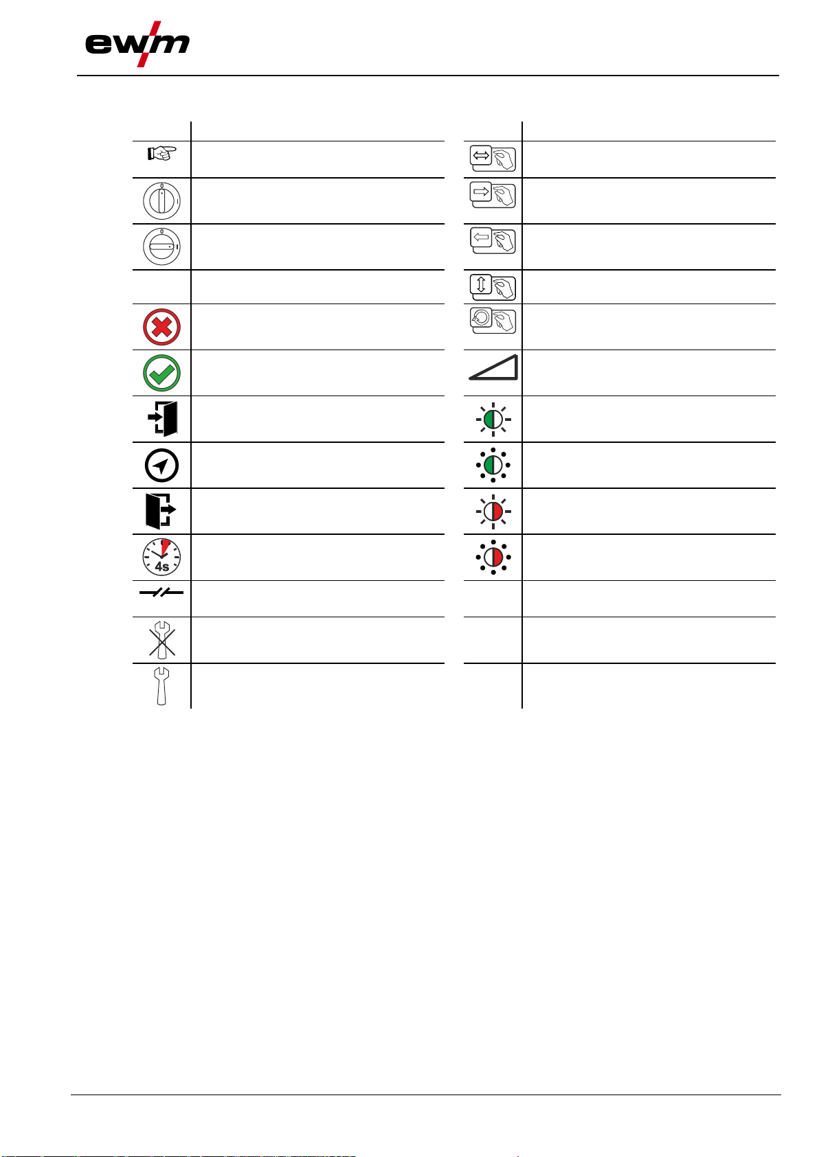
2.2 Explanation of icons.......................................................................................................................5
2.3 Part of the complete documentation..............................................................................................6
3Intended use...........................................................................................................................................7
3.1 Applications....................................................................................................................................7
3.1.1 For operation only with the following equipment............................................................7
3.2 Documents which also apply.........................................................................................................7
3.2.1 Warranty.........................................................................................................................7
3.2.2 Declaration of Conformity...............................................................................................7
3.2.3 Service documents (spare parts and circuit diagrams)..................................................7
4Machine description –quick overview ................................................................................................8
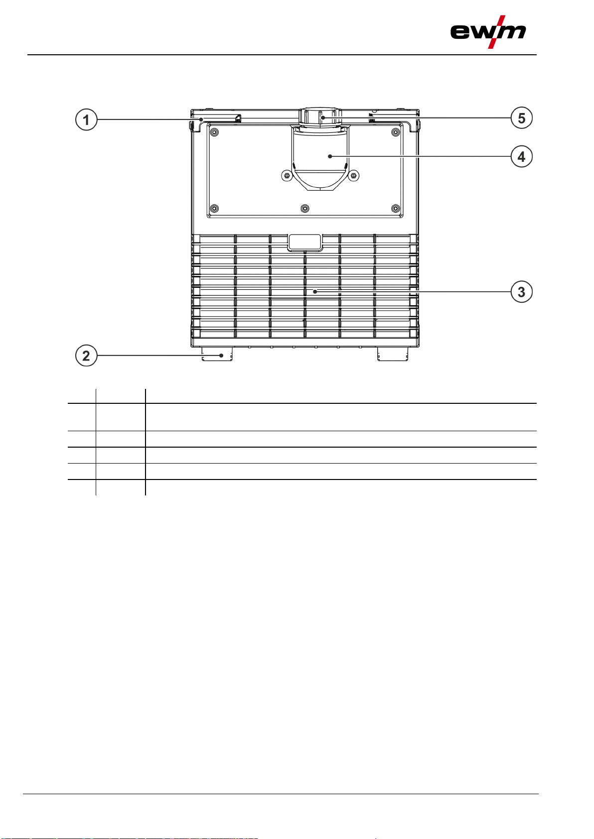
4.1 Front view ......................................................................................................................................8
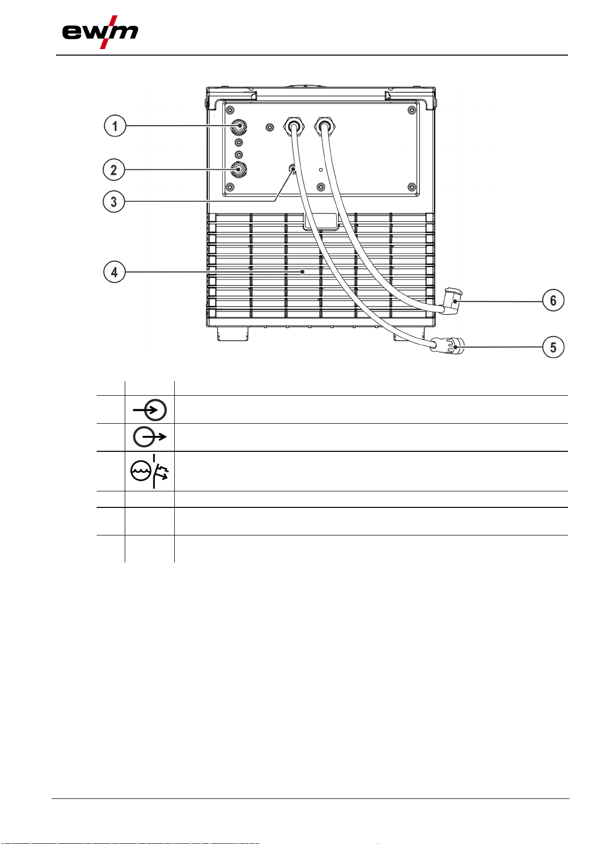
4.2 Rear view.......................................................................................................................................9
5Design and function.............................................................................................................................10
5.1 Assembly/disassembly ................................................................................................................10
5.1.1 Connecting the supply lines .........................................................................................10
5.1.2 Coolant line connections..............................................................................................11
5.2 Transport and installation ............................................................................................................11
5.2.1 Machine cooling............................................................................................................11
5.2.2 Ambient conditions.......................................................................................................11
5.2.2.1 In operation...................................................................................................12
5.2.2.2 Transport and storage...................................................................................12
5.2.3 Welding torch cooling system.......................................................................................12
5.2.3.1 Approved coolants overview.........................................................................12
5.2.3.2 Maximal hose package length ......................................................................13
5.3 Functional characteristics............................................................................................................13
5.3.1 Adding coolant..............................................................................................................14
6Maintenance, care and disposal.........................................................................................................15
6.1 General........................................................................................................................................15
6.2 Cleaning.......................................................................................................................................15
6.2.1 Dirt filter........................................................................................................................15
6.3 Maintenance work, intervals........................................................................................................16
6.3.1 Daily maintenance tasks ..............................................................................................16
6.3.2 Monthly maintenance tasks..........................................................................................16
6.3.3 Annual test (inspection and testing during operation)..................................................16
6.4 Disposing of equipment ...............................................................................................................17
7Rectifying faults ...................................................................................................................................18
7.1 Checklist for rectifying faults........................................................................................................18
7.2 Vent coolant circuit.......................................................................................................................19
7.3 Fixing the pump shaft (coolant circuit).........................................................................................19
8Technical data ......................................................................................................................................21
8.1 Cool 50 MPW50...........................................................................................................................21
9Accessories..........................................................................................................................................22
9.1 General accessories....................................................................................................................22
10 Appendix A ...........................................................................................................................................23
10.1 Searching for a dealer .................................................................................................................23

For your safety
Notes on the use of these operating instructions
4
099-008818-EW501
30.05.2018
2 For your safety
2.1 Notes on the use of these operating instructions
DANGER
Working or operating procedures which must be closely observed to prevent imminent
serious and even fatal injuries.
•Safety notes include the "DANGER" keyword in the heading with a general warning symbol.
•The hazard is also highlighted using a symbol on the edge of the page.
WARNING
Working or operating procedures which must be closely observed to prevent serious
and even fatal injuries.
•Safety notes include the "WARNING" keyword in the heading with a general warning
symbol.
•The hazard is also highlighted using a symbol in the page margin.
CAUTION
Working or operating procedures which must be closely observed to prevent possible
minor personal injury.
•The safety information includes the "CAUTION" keyword in its heading with a general
warning symbol.
•The risk is explained using a symbol on the edge of the page.
Technical aspects which the user must observe to avoid material or equipment damage.
Instructions and lists detailing step-by-step actions for given situations can be recognised via bullet
points, e.g.:
•Insert the welding current lead socket into the relevant socket and lock.

For your safety
Explanation of icons
099-008818-EW501
30.05.2018
5
2.2 Explanation of icons
Symbol
Description
Symbol
Description
Indicates technical aspects which the
user must observe.
Activate and release / Tap / Tip
Switch off machine
Release
Switch on machine
Press and hold
Switch
Incorrect / Invalid
Turn
Correct / Valid
Numerical value –adjustable
Input
Signal light lights up in green
Navigation
Signal light flashes green
Output
Signal light lights up in red
Time representation (e.g.: wait 4 s /
actuate)
Signal light flashes red
Interruption in the menu display (other
setting options possible)
Tool not required/do not use
Tool required/use

For your safety
Part of the complete documentation
6
099-008818-EW501
30.05.2018
2.3 Part of the complete documentation
These operating instructions are part of the complete documentation and valid only in
combination with all other parts of these instructions! Read and observe the operating
instructions for all system components, especially the safety instructions!
The illustration shows a general example of a welding system.
Figure 2-1
Item
Documentation
A.1
Options conversion instructions
A.2
Power source
A.3
Cooling unit, voltage converter, tool box etc.
A.4
Transport cart
A.5
Welding torch
A.6
Remote control
A.7
Controller
A
Complete documentation

Intended use
Applications
099-008818-EW501
30.05.2018
7
3 Intended use
WARNING
Hazards due to improper usage!
The machine has been constructed to the state of the art and any regulations and
standards applicable for use in industry and trade. It may only be used for the welding
procedures indicated at the rating plate. Hazards may arise for persons, animals and
material objects if the equipment is not used correctly. No liability is accepted for any
damages arising from improper usage!
•The equipment must only be used in line with its designated purpose and by trained or
expert personnel!
•Do not improperly modify or convert the equipment!
3.1 Applications
These cooling modules are designed solely for cooling welding torches.
We can only guarantee smooth and trouble-free operation when used in conjunction with the welding
machines, welding torches, coolants and accessory components from our range.
3.1.1 For operation only with the following equipment
•Microplasma 25, 55, 105
3.2 Documents which also apply
3.2.1 Warranty
For more information refer to the "Warranty registration" brochure supplied and our information regarding
warranty, maintenance and testing at www.ewm-group.com!
3.2.2 Declaration of Conformity
The labelled product complies with the following EC directives in terms of its design and
construction:
•Low Voltage Directive (LVD)
•Electromagnetic Compatibility Directive (EMC)
•Restriction of Hazardous Substance (RoHS)
In case of unauthorised changes, improper repairs, non-compliance with specified deadlines for "Arc
Welding Equipment –Inspection and Testing during Operation," and/or prohibited modifications which
have not been explicitly authorised by the manufacturer, this declaration shall be voided. An original
document of the specific declaration of conformity is included with every product.
3.2.3 Service documents (spare parts and circuit diagrams)
WARNING
Do not carry out any unauthorised repairs or modifications!
To avoid injury and equipment damage, the unit must only be repaired or modified by
specialist, skilled persons!
The warranty becomes null and void in the event of unauthorised interference.
•Appoint only skilled persons for repair work (trained service personnel)!
Original copies of the circuit diagrams are enclosed with the unit.
Spare parts can be obtained from the relevant authorised dealer.

Machine description –quick overview
Front view
8
099-008818-EW501
30.05.2018
4 Machine description – quick overview
4.1 Front view
Figure 4-1
Item
Symbol
Description 0
1
Screw connector
Connects cooling module and welding machine
2
Machine feet
3
Cooling air inlet
4
Coolant tank > see 5.2.3 chapter
5
Coolant tank cap

Machine description –quick overview
Rear view
099-008818-EW501
30.05.2018
9
4.2 Rear view
Figure 4-2
Item
Symbol
Description 0
1
Quick connect coupling, red
Coolant return from the welding torch
2
Quick connect coupling, blue
Coolant supply to the welding torch
3
Automatic cut-out of coolant pump key button
press to reset a triggered fuse
4
Cooling air outlet
5
Connector plug, 8-pole
Cooling unit control lead
6
Connector plug, 5-pole
Cooling unit voltage supply

Design and function
Assembly/disassembly
10
099-008818-EW501
30.05.2018
5 Design and function
WARNING
Risk of injury from electrical voltage!
Contact with live parts, e.g. power connections, can be fatal!
•Observe the safety information on the first pages of the operating instructions!
•Commissioning must be carried out by persons who are specifically trained in handling
power sources!
•Connect connection or power cables while the machine is switched off!
Read and observe the documentation to all system and accessory components!
5.1 Assembly/disassembly
WARNING
Risk of accidents due to screw connectors that are not locked!
Attention must be paid to cleanliness and correct installation
when mounting a power source with a cooling module. The
cooling module could become loose if not properly mounted,
thereby causing serious injuries.
•Remove dirt from the feet of the power source's unit and the screw
connectors of the cooling module before mounting.
•Check that the connections are locked in place before each
transport
(push the screw connections back in as far as they will go)!
Assembly and disassembly is very simple and doesn't require any tools.
Figure 5-1
•Open out all four screw connectors on the cooling module as far as they will go.
•Position the welding machine precisely with the machine's feet in the openings of the screw
connectors provided on the cooling module.
•Push all four screwed connectors back in as far as they will go.
5.1.1 Connecting the supply lines
Control and supply lead to the welding machine
The cooling module and welding machine are connected using two leads.
•Insert the control lead plug on the welding machine.
•Insert the power supply lead plug on the welding machine.

Design and function
Transport and installation
099-008818-EW501
30.05.2018
11
5.1.2 Coolant line connections
Figure 5-2
Item
Symbol
Description 0
1
Power source
2
Hose bridge
Coolant-connection lead (red/blue)
The item described in the following is part of the machine´s scope of delivery.
•Lock connecting nipples of the cooling water tubes into the corresponding quick connect couplings:
Return line red to quick connect coupling, red (coolant return) and
supply line blue to quick connect coupling, blue (coolant supply).
5.2 Transport and installation
WARNING
Risk of accident due to improper transport of machines that must not be lifted!
Do not lift or suspend the machine! The machine can drop and cause injuries! The
handles, straps or brackets are suitable for transport by hand only!
•The machine must not be suspended or lifted using a crane.
5.2.1 Machine cooling
Insufficient ventilation results in a reduction in performance and equipment damage.
•Observe the ambient conditions!
•Keep the cooling air inlet and outlet clear!
•Observe the minimum distance of 0.5 m from obstacles!
5.2.2 Ambient conditions
T he machine must not be operated in the open air and must only be set up and operated on a
suitable, stable and level base!
•The operator must ensure that the ground is non-slip and level, and provide sufficient lighting
for the place of work.
•Safe operation of the machine must be guaranteed at all times.
Equipment damage due to contamination!
Unusually high amounts of dust, acids, corrosive gases or substances can damage the machine
(observe maintenance intervals > see 6.3 chapter).
•Avoid large amounts of smoke, steam, oily fumes, grinding dust and corrosive ambient air!

Design and function
Transport and installation
12
099-008818-EW501
30.05.2018
5.2.2.1 In operation
Temperature range of the ambient air:
•-25 °C to +40 °C (-13 F to 104 F)
Relative humidity:
•up to 50 % at 40 °C (104 F)
•up to 90 % at 20 °C (68 F)
5.2.2.2 Transport and storage
Storage in a closed room, temperature range of the ambient air:
•-30 °C to +70 °C (-22 F to 158 F)
Relative humidity
•up to 90 % at 20 °C (68 F)
5.2.3 Welding torch cooling system
Insufficient frost protection in the welding torch coolant!
Depending on the ambient conditions, different liquids are used for cooling the welding
torch > see 5.2.3.1 chapter.
Coolants with frost protection (KF 23E) must be checked regularly to ensure that the frost
protection is adequate to prevent damage to the machine or the accessory components.
•The coolant must be checked for adequate frost protection with the TYP 1 frost protection
tester .
•Replace coolant as necessary if frost protection is inadequate!
Coolant mixtures!
Mixtures with other liquids or the use of unsuitable coolants result in material damage and
renders the manufacturer's warranty void!
•Only use the coolant described in this manual (overview of coolants).
•Do not mix different coolants.
•When changing the coolant, the entire volume of liquid must be changed.
Dispose of the coolant in accordance with local regulations and the material safety data sheets.
5.2.3.1 Approved coolants overview
Coolant
Temperature range
KF 23E
-10 °C to +40 °C

Design and function
Functional characteristics
099-008818-EW501
30.05.2018
13
5.2.3.2 Maximal hose package length
All information relates to the total hose package length of the complete welding system and presents
exemplary configurations (of components of the EWM product portfolio with standard lengths). A straight
kink-free installation is to be ensured, taking into account the max. delivery height.
Pump: Pmax = 3,5 bar (0.35 MPa)
--------------------------------------------------------------------------------------------------------------------- ►
Power source
Hose package
Wire feeder
miniDrive
Welding torch
Max.
Compact
(25 m / 82 ft.)
(5 m / 16 ft.)
30 m
98 ft.
(20 m / 65 ft.)
(5 m / 16 ft.)
Decompact
(25 m / 82 ft.)
(5 m / 16 ft.)
(15 m / 49 ft.)
(10 m / 32 ft.)
(5 m / 16 ft.)
Pump: Pmax = 4.5 bar (0.45 MPa)
--------------------------------------------------------------------------------------------------------------------- ►
Power source
Hose package
Wire feeder
miniDrive
Welding torch
Max.
Compact
(25 m / 82 ft.)
(5 m / 16 ft.)
30 m
98 ft.
(30 m / 98 ft.)
(5 m / 16 ft.)
40 m
131 ft.
Decompact
(40 m / 131 ft.)
(5 m / 16 ft.)
45 m
147 ft.
(40 m / 131 ft.)
(25 m / 82 ft.)
(5 m / 16 ft.)
70 m
229 ft.
5.3 Functional characteristics
Overloading the coolant pump!
The cooling unit must not be put into operation without a welding torch connected, as otherwise
the coolant pump will be destroyed due to thermal overload (the coolant cannot circulate in the
coolant circuit).
•Connect the coolant connections for the water cooled welding torch to the cooling module.
•If air-cooled welding torches are used, the control and supply line between the cooling module
and welding machine must be disconnected!
The cooling modules (pump and fan) are controlled by the welding machine only.
The welding machine automatically detects and displays a lack of coolant
(see the welding machine operating instructions).

Design and function
Functional characteristics
14
099-008818-EW501
30.05.2018
5.3.1 Adding coolant
If the cooling system is empty or only insufficiently filled with coolant, the coolant pump is
automatically switched off after approx. one minute (protection against destruction). At the same
time, the welding data display signals the lack of coolant or low coolant level.
•Reset the coolant error, fill coolant and repeat the operation.
The unit is supplied ex works with a minimum level of coolant.
Figure 5-3
Item
Symbol
Description 0
1
Coolant tank cap
2
Coolant filter sieve
3
Coolant tank > see 5.2.3 chapter
4
"Min" mark
Minimum coolant level
•Unscrew and remove the coolant tank sealing cover.
•Check filter sieve insert for dirt, clean if necessary and reinsert into position.
•Top up coolant to the filter sieve insert, close sealing cover again.
The level of coolant must never fall below the “min” mark.
If there is less coolant in the coolant tank than the minimum required you may need to vent the
coolant circuit. In this case the welding machine will automatically shut down the coolant pump
and signal an error, > see 7.2 chapter.

Maintenance, care and disposal
General
099-008818-EW501
30.05.2018
15
6 Maintenance, care and disposal
6.1 General
DANGER
Risk of injury due to electrical voltage after switching off!
Working on an open machine can lead to fatal injuries!
Capacitors are loaded with electrical voltage during operation. Voltage remains present
for up to four minutes after the mains plug is removed.
1.Switch off machine.
2.Remove the mains plug.
3.Wait for at last 4 minutes until the capacitors have discharged!
WARNING
Incorrect maintenance, testing and repair!
Maintenance, testing and repair of the machine may only be carried out by skilled and
qualified personnel. A qualified person is one who, because of his or her training,
knowledge and experience, is able to recognise the dangers that can occur while testing
welding power sources as well as possible subsequent damage, and who is able to
implement the required safety procedures.
Observe the maintenance instructions > see 6.3 chapter.
•In the event that the provisions of one of the below-stated tests are not met, the machine
must not be operated again until it has been repaired and a new test has been carried out!
Repair and maintenance work may only be performed by qualified authorised personnel; otherwise the
right to claim under warranty is void. In all service matters, always consult the dealer who supplied the
machine. Return deliveries of defective equipment subject to warranty may only be made through your
dealer. When replacing parts, use only original spare parts. When ordering spare parts, please quote the
machine type, serial number and item number of the machine, as well as the type designation and item
number of the spare part.
Under the specified ambient conditions and normal working conditions this machine is essentially
maintenance-free and requires just a minimum of care.
Contamination of the machine may impair service life and duty cycle. The cleaning intervals depend on
the ambient conditions and the resulting contamination of the machine. The minimum interval is every six
months.
6.2 Cleaning
•Clean the outer surfaces with a moist cloth (no aggressive cleaning agents).
•Purge the machine venting channel and cooling fins (if present) with oil- and water-free compressed
air. Compressed air may overspeed and destroy the machine fans. Never direct the compressed air
directly at the machine fans. Mechanically block the fans, if required.
•Check the coolant for contaminants and replace, if necessary.
6.2.1 Dirt filter
The duty cycle of the welding machine decreases as an effect of the reduced cooling air volume. The dirt
filter must be remove at regular intervals and cleaned by blowing out with compressed air (depending on
the level of soiling).

Maintenance, care and disposal
Maintenance work, intervals
16
099-008818-EW501
30.05.2018
6.3 Maintenance work, intervals
6.3.1 Daily maintenance tasks
Visual inspection
•Mains supply lead and its strain relief
•Gas cylinder securing elements
•Check hose package and power connections for exterior damage and replace or have repaired by
specialist staff as necessary!
•Gas tubes and their switching equipment (solenoid valve)
•Check that all connections and wearing parts are hand-tight and tighten if necessary.
•Check correct mounting of the wire spool.
•Wheels and their securing elements
•Transport elements (strap, lifting lugs, handle)
•Other, general condition
Functional test
•Operating, message, safety and adjustment devices (Functional test)
•Welding current cables (check that they are fitted correctly and secured)
•Gas tubes and their switching equipment (solenoid valve)
•Gas cylinder securing elements
•Check correct mounting of the wire spool.
•Check that all screw and plug connections and replaceable parts are secured correctly, tighten if
necessary.
•Remove any spatter.
•Clean the wire feed rollers on a regular basis (depending on the degree of soiling).
6.3.2 Monthly maintenance tasks
Visual inspection
•Casing damage (front, rear and side walls)
•Wheels and their securing elements
•Transport elements (strap, lifting lugs, handle)
•Check coolant tubes and their connections for impurities
Functional test
•Selector switches, command devices, emergency stop devices, voltage reducing devices, message
and control lamps
•Check that the wire guide elements (inlet nipple, wire guide tube) are fitted securely.
•Check coolant tubes and their connections for impurities
•Check and clean the welding torch. Deposits in the torch can cause short circuits and have a negative
impact on the welding result, ultimately causing damage to the torch.
6.3.3 Annual test (inspection and testing during operation)
A periodic test according to IEC 60974-4 "Periodic inspection and test" has to be carried out. In addition
to the regulations on testing given here, the relevant local laws and regulations must also be observed.
For more information refer to the "Warranty registration" brochure supplied and our information regarding
warranty, maintenance and testing at www.ewm-group.com!

Maintenance, care and disposal
Disposing of equipment
099-008818-EW501
30.05.2018
17
6.4 Disposing of equipment
Proper disposal!
The machine contains valuable raw materials, which should be recycled, and electronic
components, which must be disposed of.
•Do not dispose of in household waste!
•Observe the local regulations regarding disposal!
•According to European provisions (Directive 2012/19/EU on Waste of Electrical and Electronic
Equipment), used electric and electronic equipment may no longer be placed in unsorted municipal
waste. It must be collected separately. The symbol depicting a waste container on wheels indicates
that the equipment must be collected separately.
This machine has to be disposed of, or recycled, in accordance with the waste separation systems in
use.
•According to German law (law governing the distribution, taking back and environmentally correct
disposal of electric and electronic equipment (ElektroG)), used machines are to be placed in a
collection system separate from unsorted municipal waste. The public waste management utilities
(communities) have created collection points at which used equipment from private households can be
disposed of free of charge.
•Information about returning used equipment or about collections can be obtained from the respective
municipal administration office.
•In addition to this, returns are also possible throughout Europe via EWM sales partners.

Rectifying faults
Checklist for rectifying faults
18
099-008818-EW501
30.05.2018
7 Rectifying faults
All products are subject to rigorous production checks and final checks. If, despite this, something fails to
work at any time, please check the product using the following flowchart. If none of the fault rectification
procedures described leads to the correct functioning of the product, please inform your authorised
dealer.
7.1 Checklist for rectifying faults
The correct machine equipment for the material and process gas in use is a fundamental
requirement for perfect operation!
Please observe the welding machine operating instructions.
Legend
Symbol
Description
Fault/Cause
Remedy
Coolant error/no coolant flowing
Insufficient coolant flow
Check coolant level and refill if necessary
Eliminate kinks in conduit system (hose packages)
Extend and lay out the torch hose package
Reset automatic cutout of the coolant pump by activating
Air in the coolant circuit
Vent coolant circuit > see 7.2 chapter
Coolant pump blocked
Switch on pump shaft (specialist staff only) > see 7.3 chapter
Functional errors
Connection problems
Make control lead connections and check that they are fitted correctly.

Rectifying faults
Vent coolant circuit
099-008818-EW501
30.05.2018
19
7.2 Vent coolant circuit
To vent the cooling system always use the blue coolant connection, which is located as deep as
possible inside the system (close to the coolant tank)!
Figure 7-1
7.3 Fixing the pump shaft (coolant circuit)
WARNING
Do not carry out any unauthorised repairs or modifications!
To avoid injury and equipment damage, the unit must only be repaired or modified by
specialist, skilled persons!
The warranty becomes null and void in the event of unauthorised interference.
•Appoint only skilled persons for repair work (trained service personnel)!
Risk of injury from electrical voltage!
Voltages can cause potentially fatal electric shocks and burns on contact. Even low
voltages can cause a shock and lead to accidents.
•Never touch live components such as welding current sockets or stick, tungsten or wire
electrodes!
•Always place torches and electrode holders on an insulated surface!
•Wear the full personal protective equipment (depending on the application)!
•The machine may only be opened by qualified personnel!
•The device must not be used to defrost pipes!

Rectifying faults
Fixing the pump shaft (coolant circuit)
20
099-008818-EW501
30.05.2018
Continuing non-use and impurities in the coolant may result in the the coolant pump not being in proper
working order.
Figure 7-2
•Switch off machine at the main switch.
•Insert a plain slot screwdriver with a maximum tip width of 6.5 mm through the maintenance opening
and place in the centre of the pump shaft. Turn the screwdriver clockwise until the pump shaft can be
easily rotated again.
•Remove screwdriver.
•Switch on the power source at the main switch.
Table of contents
Other EWM Accessories manuals