BlackGlobe Temperature Sensor for Heat Stress
4. Overview
The BlackGlobe uses a thermistor inside a 15.24 cm (6 in) hollow copper
sphere, painted black to measure radiant temperature. This measurement along
with the measurement of ambient air and wet-bulb temperatures may be used to
calculate the WBGT index, which is sometimes referred to as the Humidex.
Sensor cable length is specified at the time of order. Do not exceed 1000 feet
of cable.
To calculate the wet-bulb globe thermometer index (WBGT), the measurement
of the BlackGlobe (radiant heat), wet-bulb (evaporative heat), and ambient air
(dry-bulb) temperatures are required. The wet-bulb temperature can be
calculated using air temperature and relative humidity if a wet-bulb
thermometer is not available. See Section 7.2, Calculations.
5. Specifications
Temperature Measurement Range: –5° to +95°C
Temperature Survival Range: –50° to +100°C
Thermistor Interchangeability Error: Typically < ±0.2°C over 0°C to 70°C
and ±0.3 at 95°C
Polynomial Linearization Error: < ±0.5°C over –7°C to +90°C
Near Normal Emittance: 0.957
Maximum Cable Length: 305 m (1000 ft)
The black outer jacket of the cable is Santoprene@ rubber. This
compound was chosen for its resistance to temperature extremes,
moisture, and UV degradation. However, this jacket will support
combustion in air. It is rated as slow burning when tested
according to V.L. 94 H.B. and will pass FMVSS302. Local fire
codes may preclude its use inside buildings.
NOTE
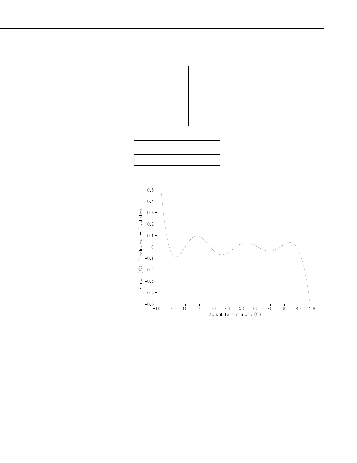
5.1 Accuracy
The overall probe accuracy is a combination of the thermistor’s
interchangeability specification, the precision of the bridge resistors, and the
Steinhart-Hart equation error (CRBasic dataloggers) or the polynomial error
(Edlog dataloggers). In a worst case, all errors add to an accuracy of ±0.3°C
over the range of –3° to 90°C and ±0.7°C over the range of –5° to 95°C. The
major error component is the interchangeability specification of the thermistor,
tabulated in TABLE 5-1 and plotted in FIGURE 5-2. For the range of 0° to
50°C, the interchangeability error is predominantly offset and can be
determined with a single point calibration. Compensation can then be done
with an offset entered in the measurement instruction. The bridge resistors are
0.1% tolerance with a 10 ppm temperature coefficient. Polynomial errors are
tabulated in TABLE 5-2 and plotted in FIGURE 5-1.
2