Red Sound System DarkStar Vocoda User manual

INSTALLING THE SOFTWAREINSTALLING THE SOFTWARE
1
OWNERS MANUAL
INSTALLATION
Before attempting to install your new VOCODA software please follow the instructions below.
Each time you install a software conversion, the internal memory that contains all
existing PROGRAM sound data will be re-initialised [erased and re-set]. Therefore, please follow the procedures in the
UTILITY section of the main manual, pages 31/32 to save all your sound data as system exclusive dumps before starting
any conversion installation work.
Your VOCODA software conversion kit should contain the following:
1. EPROM chip 2. Panel overlay 3. Chip removal device 4. VOCODA Manual [no problem if you’re reading this!]
If any part of the kit is missing please contact your local distributor/dealer or RED Sound direct.
The EPROM chip is a static sensitive device and, although quite robust, can be damaged if handled inappropriately. To
avoid accidental damage, please observe these simple anti-static precautions:
* Touch a good earth point to discharge any static build-up before commencing work [metal radiator, pipe or
earthed domestic/sound equipment]
* Avoid excessive movement after discharging [walking across man-made fibre carpets will instantly create static!]
* Avoid touching EPROM pins - handle at either end of chip casing.
Open the rear access panel as described in the main DARKSTAR manual, page 33.
Note the correct orientation of EPROM [pin 1 ‘notched’ end towards access panel screw fixing].
Use the supplied chip removal device to withdraw the EPROM [position tweezer pins under each end of the chip and pull
directly upwards]. Remove new VOCODA chip from the anti-static pack and store the removed DARKSTAR synthesizer
EPROM in its place for safe-keeping.
Check all pins on the VOCODA chip are in-line, straighten any if necessary before attempting to fit the chip. Observing the
correct polarity [as stated above], carefully place the EPROM into the chip socket, checking that all pins are located
correctly [jiggle pins into position] before pressing home firmly. Check that no foreign objects have entered the case before
closing the access panel.
This operation re-sets the on-board memory with the
specific VOCODA programs, sounds and parameters. HAVE YOU BACKED-UP YOUR PREVIOUS DATA! - if not, replace
the original EPROM and carry out a full sys-ex dump now.
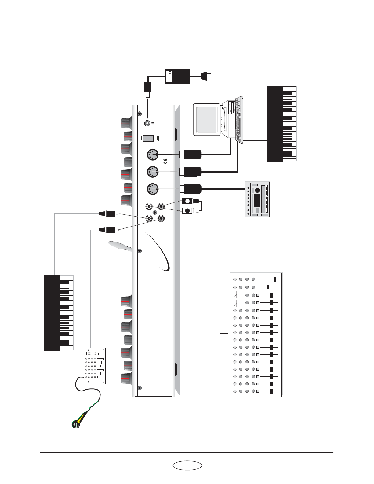
Connect the power supply to DARKSTAR but, ,
. Now switch on the power. The test software should be running.
The first test checks the MIDI IN / OUT ports [main display shows ‘SE_ F’]. This test should be ignored. To bypass the MIDI
test, press the [AUDITION] button once. The re-initialisation code should now run, the display counting up the following:
display shows IP 01...64 display shows IS 01...96
display shows CP 01...64 display shows CS 01...96
This process takes approximately 1½ minutes to complete. Afterwards, the full test software will be automatically activated
[buttons, LED’s and pot tests]. Please ignore this test.
Peel-off the backing paper from the supplied panel overlay and place this onto the DARKSTAR front panel for identification
of the re-labeled vocoder controls. DARKSTAR has now been successfully converted into a VOCODA!
BACK-UP EXISTING DATA NOW! -
TURN OFF POWER AND REMOVE ALL CONNECTIONS BEFORE PROCEEDING!
REMOVING/INSTALLING CHIPS -
** SEE NOTE BELOW! RE-INITIALISING THE SOFTWARE -
1. Program initialise - 2. Sequence initialise -
3. Program check - 4. Sequence check -
When you see the LED indicators tracking across the panel in
sequence it is safe to turn the power off.
NOTE: this back-up operation should be carried out each time a software conversion is made.
press and hold down the [AUDITION] &
[PART 1] buttons simultaneously - see diagram on page 2
before switching the power on
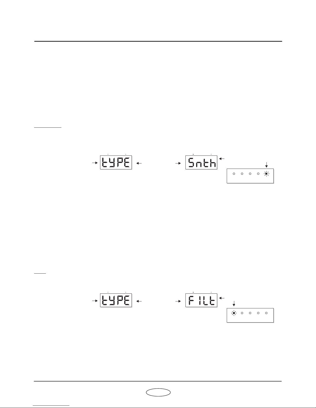
**IMPORTANT NOTE! REMEMBER TO FOLLOW THE ABOVE RE-INITIALISATION PROCEDURE TIME YOU
CHANGE APPLICATIONS I.E.
SYNTH TO VOCODA = RE- INITIALISE
VOCODA TO SYNTH = RE- INITIALISE
EVERY

2
FRONT PANELFRONT PANEL
1
3
2
4
7
PARAMETER
AUDITION
BANK
4
3
2
1
8
7
PULSE
SINE SAMPLE RANDOM
SQUARE
TRI
RAMP
UTILITY
DELAY
SPEED
(MIDI CLOCK)
LEVEL PORTAMENTO
SHAPE
TREMOLO
Envelope 1
LFO1
(SHIFT)
Envelopes
(SHIFT)
Max
Max
LFO’s
(SHIFT) EDIT
2
1
MENU
PROG
Envelope 2
LFO2
DOWN
MENU
VA L U E
VA L U E
MENU
UP
(SHIFT)
Min
Min
PITCH MOD
WAVEFORM
(PWM)
DETUNE
PULSE WIDTH
Oscillators
Max
Oscillator 1
Oscillator2
Min
(OSC 2 PITCH)
VELOCITY LEVEL
5
467
3
2
1
0
DECAY
AT TA C K RELEASE
SUSTAIN
Max
Max
Max Max
Min
Min
(VELOCITY)
Min Min
www.redsound.com
RED
EDIT MODULATION
MIDI
LFO
OUTPUT
3
6
5
4
PORTA/TRIGGER
/ VALUE
OUTPUT
BANK
00
Max
+10 +2
semitones
-2
semitones
Min
-10
LFO SHAPE
OSCILLATORS
PROG
Off
Off
-
-
+
+
2:1
3:2 3:1 4:1
4:3
1:1
SYNC
FREE
(OSC 1-2 MIX) (RING MODULATION)
Vocoda
PANNING
SYNTH
SEQ OUT
OSC
VOC’R
FILTER
SPEED
(GLIDE)
(PRESET)
PARAMETER
Vocoder
Max Max Max
Min Min Min
Vocoder Off
Vocoder On
VOCODER MODE OVERLOAD
VOCODER SEQUENCES
VOCODER SEQUENCE
PROGRAM/
SEQUENCE
RECORD
VA L U E
SEQ
VOICE FILTER
(MIDI CLOCK)
SEQUENCER SOUND
ON/OFF
LEVEL
INPUT
OUTPUT
OSC2RATIO MODE
11 10
12 9
658
VOCODER CONTROL
Max
Min
LOW HIGH
BOOST
Max
Min
DarkStar Vocoda
RE-INITIALISING:
Press AUDITION and PART/SEQ 1 together
before apply power

1.
2.
3.
4.
5.
6.
7.
8.
9.
10.
11.
12.
OSCILLATORS:
ENVELOPES:
LFO’S:
VOCODER:
VOCODER SEQUENCES:
MENU:
AUDITION:
PROGRAM:
OUTPUT:
PARAMETER/VALUE DISPLAY:
VOCODER CONTROL:
UTILITY:
This section features [WAVEFORM], [PITCH MOD], [PULSE WIDTH] and [DETUNE] controls
for each oscillator. The large [OSCILLATOR] button switches between oscillators1&2.The[SHIFT] button is used
to access the [OSC 2 PITCH], [PWM], [OSC MIX] and [RING MOD] controls in the oscillator sub-menu.
This section features [ATTACK], [DECAY], [SUSTAIN] and [RELEASE] controls for each
envelope. The large [ENVELOPE] button switches between envelopes1&2.The[SHIFT] button is used to access
the [VELOCITY] control in the envelope sub-menu.
This section features [SPEED], [DELAY] and [SHAPE] controls for each LFO. The large [LFO] button
switches between LFO1&2.The[SHIFT] button is used to access the [MIDI CLOCK] control in the LFO sub-
menu.
This section features [SPEED], [SOUND VALUE] and [SOUND PARAMETER] controls for the
vocoder. The large [VOCODER] button switches the vocoder on and off. The [SHIFT] button is used to access the
[MIDI CLOCK], [GLIDE] and [PRESET] controls in the vocoder sub-menu.
These buttons are used to select and record vocoder sequences. You can create
and store 4 totally different sequences in each of the 24 programs in banks 1,2 and 3.
This section features 8 menu buttons and a 4-way keypad. The MENU buttons are used to select
additional parameters for editing whilst the [EDIT] keypad is used to scroll up and down the menus and change their
values.
This button can be used to trigger the envelopes in [SYNTHESIZER], [FILTER] modes etc.
This section features the [PROGRAM/SEQUENCE] and [BANK] buttons which are used to select
the 8 banks of 8 programs (total programs = 64, sequences = 96).
This button is used to access the [LEVEL], [PANNING], [TREMOLO] and [PORTAMENTO]
parameters.
This 4-digit LED display shows bank/program numbers, parameter
information and edit values.
The joystick control ‘morphs’ the spectrum of the vocoder/filter sound.
This button is used to access the SYSTEM EXCLUSIVE utility parameters.
FRONT PANEL FEATURESFRONT PANEL FEATURES
3
FRONT PANEL FEATURES
OWNERS MANUAL

213
1.
2.
3.
INPUT 1 - RCA Phono Connector
INPUT 2 - RCA Phono Connector
STEREO OUTPUT - RCA Phono Connectors
When VOCODER mode is selected, use this socket to connect the mono sound source.
When VOCODER/INTERNAL OSCILLATOR modes are selected, use this socket to connect the pre-amplified
microphone signal.
Use these sockets to connect DARKSTAR VOCODA to your mixing desk or amplification system.
NOTE: in other modes
such as FILTER mode, use as LEFT channel input for stereo sound processing.
NOTE: in other modes such as FILTER mode, use as RIGHT channel input for stereo sound
processing.
REAR PANELREAR PANEL
4
MIDI
OUT INTHRU
MADE IN ENGLAND
OUTEXT.
INPUT
1L
2R
POWER
9v DCOFF
ON
CAUTION: DO NOT OPEN CASE
REFER TO QUALIFIED SERVICE PERSONNEL
NO USER SERVICEABLE PARTS INSIDE
DarkStar
www.redsound.com
RED
8 VOICE POLYPHONIC SYNTHESIZER
+
-
RED Sound Systems Ltd
DarkStar Vocoda

5
OWNERS MANUAL
CONNECTIONS
MIDI
OUT IN
THRU
MADE IN ENGLAND
OUT
EXT.
INPUT
1L
2R
POWER
9v DC
OFF
ON
CAUTION: DO NOT OPEN CASE
REFER TO QUALIFIED SERVICE PERSONNEL
NO USER SERVICEABLE PARTS INSIDE
DarkStar
www.redsound.com
RED
8 VOICE POLYPHONIC SYNTHESIZER
+
-
RED Sound Systems Ltd
MIDI IN
MIDI IN
MIDI OUT
MIDI SEQUENCER
MIDI KEYBOARD
SOUND SOURCE
MIXER/PRE-AMP
OTHER MIDI DEVICE
STUDIO MIXING DESK
MIC
R
L
TO
AC WALL
SOCKET
RED PSU
Typical setup for VOCODER mode

QUICK START
OVERVIEW / GETTING STARTED
If you want to quickly try out the performance of DARKSTAR VOCODA, please read the following points carefully:
Before making any connections, make sure that the power on all your equipment is turned OFF.
Connect the power supply (included) to the ‘power in’ socket on the rear panel of DARKSTAR and plug it into a
suitable AC outlet. Connect the audio cables for a basic vocoder system setup as shown on page 5.
Make sure all connections have been made correctly and the volume controls on the
mixing desk and amplifier system are turned completely down. Press the rear panel power switch on DARKSTAR.
Turn on the power of the mixing desk and then turn on the power of the amplifier system.
When DARKSTAR is powered up, the main display will show a welcome message and
the software version whilst various parameters are being set internally. When this process is complete, the display
will show the BANK and PROGRAM number. If this does not happen, check the power supply is of the correct type
and the unit was switched on correctly.
To select VOCODER mode, press the [VOCODER] MENU button and use the [EDIT]
keypad [VALUE +] and [VALUE -] buttons to set the mode to VOCODER. Press the [VOCODER] MENU button
again to exit menu.
Select a bright, string pad type sound on your connected synthesizer. Now talk or sing
into the connected microphone whilst playing chords on the keyboard to hear the full vocoder effect. Move the
joystick about to hear the effect this has on the frequency spectrum.
Please read the following “OPERATION” section carefully to fully appreciate the range of features and facilities the
DARKSTAR VOCODA conversion has to offer.
DARKSTAR VOCODA is more than just a standard vocoder. There are five operating modes which enable you to
explore many areas of creativity. The built-in mono synthesizer can be used as a sound source for ‘robotic’ style
vocoding or as a stand-alone instrument. Filter mode can be used to process external sound sources in stereo
whilst the sequence-coder allows you to create complex vocoder sequences.
After connecting DARKSTAR VOCODA to your system, press IN the power switch on the rear panel to turn the
power on. As the software initialises (takes approximately 15 seconds) rows of indicators will light in sequence, the
main display will show a welcome message followed by the software version fitted to your unit, as shown in the
example below:
When the boot-up phase is complete the last selected program (before power was switched off at the previous
session) will be recalled and displayed as follows:
DARKSTAR VOCODA is now ready to use.
CONNECTIONS:
TURNING ON THE POWER:
POWER UP INDICATIONS:
SETTING THE MODE:
USING THE VOCODER:
NOTE: The information contained in this booklet focuses on the differences between the VOCODA conversion and
the standard DARKSTAR synthesizer. Any common features/facilities are omitted from this booklet and must be
checked by reading the full DARKSTAR manual. We therefore recommend that, initially, you use the DARKSTAR
synthesizer format to familiarize yourself fully with the operating system and procedures used throughout.
QUICK STARTQUICK START
6
PARAMETER
VA L U E
PARAMETER
VA L U E
Software version = 1.01
Bank 1
Program 1
BANK
BANK
PROG
PROG
DarkStar Vocoda

VOCODER CONTROL Joystick
The DARKSTAR VOCODA conversion uses the joystick solely for frequency spectrum adjustments and this control
is available in all five modes. The vocoder filter sound can be boosted across a wide frequency range allowing you
to home-in on particular elements in the voice. Moving the joystick around will create a real-time vocoder spectrum
sweep or ‘morphing’ effect which can also be recorded via MIDI for instant playback from your sequencer.
The ‘X’ axis (left-to-right) position of the joystick controls the vocoder frequency. At the South-West (lower left)
position the frequency will be at its lowest, around 100 Hz, as shown in the following diagram:
As the joystick is moved to the right the frequency gradually increases until, at the South-East (lower right) position,
the frequency will be at its highest, around 5 kHz, as shown in the following diagram:
The ‘Y’ axis (up and down) position of the joystick controls the amount of boost to the selected frequency. This
works like a band-pass filter, boosting the frequencies about the selected frequency without affecting other
frequencies above or below.
At the South (lower) position the boost will be at its minimum. As the joystick is moved towards the North position
the selected frequency will be gradually boosted until, at the fully North (upper) position, the boost will be at its
maximum, as shown in the following diagram:
NOTE: the rotary controls in the [VOCODER] section are only used to adjust parameters for the sequencer modes
i.e. Do not expect sonic changes (as per standard DARKSTAR) from these controls unless creating a sequence.
VOCODER CONTROL
Max
Min
LOW HIGH
BOOST
Max
Min
7
OWNERS MANUAL
OPERATION
Frequency = approx
100Hz
Frequency = approx 5kHz
Boost = maximum
Boost
VOCODER CONTROL
Max
Min
LOW HIGH
BOOST
Max
Min
VOCODER CONTROL
Max
Min
LOW HIGH
BOOST
Max
Min
VOCODER CONTROL
Max
Min
LOW HIGH
BOOST
Max
Min

8
OPERATION
VOCODER SECTION
VOCODER button
VOCODER Menu
This section of the DARKSTAR VOCODA produces all the vowel sounds for the VOCODER sequencer. You can
choose from a full compliment of 16 pre-set sounds or edit the 11 band filters individually to create your own
specific tones. Controls for changing how one sound changes or ‘morphs’ into the next and sequence speed are
also included. The VOCODER menu is used to select the operating mode.
This large button switches the vocoder on and off. When the indicator is OFF the vocoder filter will be bypassed.
When the indicator is ON the vocoder filter will be active.
This is where you select the five vocoder modes. To access the settings, first press the MENU button labelled
[VOCODER], as shown in the following example:
The indicator in the [VOCODER] button will light and the main display will now alternate between the first function
and its current value, as shown below:
The four functions in the vocoder menu are:
This function sets the basic operating mode of the DARKSTAR VOCODA. There are
five selections as follows:
In this mode the unit works as a traditional vocoder combining a control signal (Mic) and external sound
source (synth). The pitch information comes from the sound source whilst the vocal sound is passed through the
11- band vocoder filter creating classic vocoder sounds.
Menu1-Type/mode [tYPE]:
-Vocoder
(SHIFT)
SYNTHSEQ OUTOSCVOC’RFILTER
SPEED
(GLIDE)
(PRESET)
PARAMETER
Vocoder
Max Max MaxMin Min Min
Vocoder Off
Vocoder On
VOCODER MODE OVERLOAD
VA L U E
VOICE FILTER
(MIDI CLOCK)
SEQUENCER SOUND
MENU
DOWN
MENU
VA L U E
VA L U E
MENU
UP
OSCILLATORSEDIT MODULATIONMIDILFOOUTPUTVOCODER PORTA/TRIGGERSEQUENCE
PARAMETER
VA L U E
PARAMETER
VA L U E
Setting = Vocoder
Function = TYPE
BANK BANKPROG PROG
Display alternates
between
DarkStar Vocoda
SYNTHSEQOSCVOC’RFILTER
VOCODER MODE

9
OWNERS MANUAL
OPERATION
When [VOCODER] mode is selected the main display and [VOCODER MODE] display will show:
EXT 1 (Left) = Connect your sound source (synthesizer etc.) to this socket.
EXT 2 (Right) = Connect your pre-amplified microphone (via mixing desk etc.) to this socket.
[VOCODER CONTROL JOYSTICK] can be used for filter spectrum adjustments
[VOCODER MENU - ‘S’ DETECTOR] can be used to add noise elements to the sound
[OUTPUT LEVEL] can be used for volume adjustments
[OUTPUT PANNING] can be used for panning effect adjustments - also LFO controls when pan source is set to
LFO1or 2.
[OUTPUT TREMOLO] can be used for tremolo effect adjustments - also LFO controls when tremolo source is set
toLFO1or2.
In this mode the unit works as a traditional vocoder combining a control signal (Mic)
and the oscillator sound source. The sound is triggered via MIDI from an external keyboard with pitch
information coming from the internal oscillators. There is an ‘S’ (emphasis) detector for adding noise to the
oscillator sound. This mode can be used to create the familiar ‘robotic’ vocoder sound. When [INTERNAL
OSCILLATOR] mode is selected the main display and [VOCODER MODE] display will show:
EXT 1 (Left) = NO CONNECTION
EXT 2 (Right) = Connect your pre-amplified microphone (via mixing desk etc.) to this socket.
[VOCODER CONTROL JOYSTICK] can be used for filter spectrum adjustments
[OSCILLATORS] section can be used to set the sound
[ENVELOPES] can be used to shape the sound
[VOCODER MENU - ‘S’ DETECTOR] can be used to add noise elements to the sound
[LFO] section can be used to vary the sound
[OUTPUT LEVEL] can be used for volume adjustments
[OUTPUT PANNING] can be used for panning effect adjustments
[OUTPUT TREMOLO] can be used for tremolo effect adjustments
In this mode the input is stereo, with the 11-band vocoder filters
being controlled by the on-board formant sequencer to shape the incoming sound. You can use this mode to layer
vocoder phrases over vocals or any sustained instrument sound. The sequencer can be triggered in a variety of
ways from the [SEQUENCE] menu. When [SEQUENCE-CODER] mode is selected the main display and
[VOCODER MODE] display will show:
Input Connections:
Key Controls/Functions:
-
Input Connections:
Key Controls/Functions:
- (disabled in banks 4 to 8)
Internal Oscillator Vocoder
Sequence-coder
internal
PARAMETER
VA L U E
PARAMETER
VA L U E
PARAMETER
VA L U E
PARAMETER
VA L U E
PARAMETER
VA L U E
PARAMETER
VA L U E
Setting = Vocoder
Setting = Internal oscillators
Setting = Sequence-coder
Function = TYPE
Function = TYPE
Function = TYPE
BANK
BANK
BANK
BANK
BANK
BANK
PROG
PROG
PROG
PROG
PROG
PROG
Display alternates
between
Display alternates
between
Display alternates
between
SYNTH
SYNTH
SYNTH
SEQ
SEQ
SEQ
OSC
OSC
OSC
VOC’R
VOC’R
VOC’R
FILTER
FILTER
FILTER
VOCODER MODE
VOCODER MODE
VOCODER MODE

10
OPERATION
Input Connections:
Key Controls/Functions:
- (disabled in banks 4 to 8)
Input Connections:
Key Controls/Functions:
-
Input Connections:
Key Controls/Functions:
EXT 1 (Left) = Audio signal left
EXT 2 (Right) = Audio signal right
[VOCODER CONTROL JOYSTICK] can be used for filter spectrum adjustments
[VOCODER SOUND SEQUENCER] section can be used to create patterns
[SEQUENCE] menu can be used to adjust trigger source
[OUTPUT LEVEL] can be used for volume adjustments
[OUTPUT PANNING] can be used for panning effect adjustments
[OUTPUT TREMOLO] can be used for tremolo effect adjustments
In this mode the on-board formant sequencer/11-band vocoder filter can
be used to shape the sound of the internal oscillators. You can use this mode to layer vocoder phrases over mono-
phonic bass/lead sounds created by the oscillators. The sequencer can be triggered in a variety of ways from the
[SEQUENCE] menu. When [SYNTHESIZER] mode is selected the main display and [VOCODER MODE] display
will show:
EXT 1 (Left) = NO CONNECTION
EXT 2 (Right) = NO CONNECTION
[VOCODER CONTROL JOYSTICK] can be used for filter spectrum adjustments
[VOCODER SOUND SEQUENCER] section can be used to create patterns
[SEQUENCE] menu can be used to adjust trigger source
[OSCILLATORS] section can be used to set the sound
[ENVELOPES] can be used to shape the sound
[LFO] section can be used to vary the sound
[OUTPUT LEVEL] can be used for volume adjustments
[OUTPUT PANNING] can be used for panning effect adjustments
[OUTPUT TREMOLO] can be used for tremolo effect adjustments
In this mode the unit works as a vocoder style spectrum filter. This can be used to process external stereo
sound sources through the filter and envelope sections, adding subtle or extreme sonic changes to the sound.
When [FILTER] mode is selected the main display and [VOCODER MODE] display will show:
EXT 1 (Left) = Audio signal left
EXT 2 (Right) = Audio signal right
[VOCODER CONTROL JOYSTICK] can be used for filter spectrum adjustments
[ENVELOPES] can be used to shape the sound
[OUTPUT LEVEL] can be used for volume adjustments
[OUTPUT PANNING] can be used for panning effect adjustments
[OUTPUT TREMOLO] can be used for tremolo effect adjustments
Synthesizer
Filter
PARAMETER
VA L U E
PARAMETER
VA L U E
PARAMETER
VA L U E
PARAMETER
VA L U E
Setting = Synthesizer
Setting = Filter
Function = TYPE
Function = TYPE
BANK
BANK
BANK
BANK
PROG
PROG
PROG
PROG
Display alternates
between
Display alternates
between
SYNTH
SYNTH
SEQ
SEQ
OSC
OSC
VOC’R
VOC’R
FILTER
FILTER
VOCODER MODE
VOCODER MODE
DarkStar Vocoda

11
OWNERS MANUAL
OPERATION
MENU 2- Gain [GAIn]:
MENU 3 - ‘S’ Gain [S Gn]:
This function sets the vocal input level when [VOCODER] and [INTERNAL OSCILLATOR]
modes are selected (not active in other modes). The vocal input is filtered into 11 bands and the levels of these
bands are detected. The GAIN setting scales these levels before they are used to scale the 11 filtered bands from
the signal input. Two of the [OVERLOAD] indicators in the VOCODER section are directly associated with this
[GAIN] setting. The [FILTER] indicator detects over-ranging on the filter calculations which results in reduced filter
quality. The [OUTPUT] indicator detects distortion of the filter output.
The [VOICE] indicator shows microphone input overload conditions at the A/D. When this lights, reduce the input
level at the microphone signal source i.e. pre-amplifier/desk output.
With the second menu selected the main display will alternate as follows:
RANGE=1to16(max)
This setting will be applied to the [VOCODER] and [INTERNAL OSCILLATOR] modes. Use the menu [EDIT VALUE
+ and VALUE - ] buttons to change the setting as follows:
This function sets the level of the ‘S’ detector when [VOCODER], [INTERNAL
OSCILLATOR] and [SYNTHESIZER] modes are selected (not active in other modes). This noise source adds
definition to the vocoder/oscillator sound. With the third menu selected the main display will alternate as follows:
RANGE = 0 (off) to 15(max)
This setting will be applied to the selected mode. Use the menu [EDIT VALUE + and VALUE - ] buttons to change
the setting as follows:
PARAMETER
VA L U E
PARAMETER
VA L U E
PARAMETER
VA L U E
PARAMETER
VA L U E
Setting = +3
Setting = 0 [OFF]
Filter “over-ranging” Filter output distortion Mic input overload
Function = GAIN
Function = ‘S’ GAIN
BANK
BANK
BANK
BANK
PROG
PROG
PROG
PROG
Display alternates
between
Display alternates
between
PARAMETER
VA L U E
PARAMETER
VA L U E
New setting = +2
New setting = +8
BANK
BANK
PROG
PROG
DOWN
DOWN
MENU
MENU
VA L U E
VA L U E
VA L U E
VA L U E
MENU
MENU
UP
UP
OSCILLATORS
OSCILLATORS
EDIT
EDIT
Press the [VALUE+]
and [VALUE -] buttons
to change the setting
Press the [VALUE+]
and [VALUE -] buttons
to change the setting
OUT OUT OUT
OVERLOAD OVERLOAD OVERLOAD
VOICE VOICE VOICEFILTER FILTER FILTER

MENU 4 - ‘S’ Spectrum [S SP]:
MENU 5 - Filter Mod [FILt]:
MENU 6 - Filter Mod Source [Src ]:
Envelope1 -
Envelope 2 -
LFO1 -
LFO2 -
This function sets the frequency of the ‘S’ detector when [VOCODER],
[INTERNAL OSCILLATOR] and [SYNTHESIZER] modes are selected (not active in other modes). Adjusting the
frequency of the noise source changes the timbre of the ‘S’ detector and overall vocoder sound. With the forth
menu selected the main display will alternate as follows:
RANGE = 0(low) to 15(high)
This setting will be applied to the selected mode. Use the menu [EDIT VALUE + and VALUE - ] buttons to change
the setting as follows:
This function allows you to apply Filter modulation to the oscillators or external sound
source. You can process any musical instrument through the filter section, even non-MIDI instruments such as
guitar, electric bass etc when the trigger mode in [PORTA/TRIGGER] menu is set to [AUDIO] - see page 21/22 for
full details.
RANGE = +7 to -7 (the center ‘0’ setting = OFF)
This function allows you to control the Filter modulation from one of four
sources as follows:
The settings of envelope 1 controls will affect the filter modulation.
The settings of envelope 2 controls will affect the filter modulation.
The settings of the LFO1 controls will affect the filter modulation.
The settings of the LFO2 controls will affect the filter modulation.
This control has two functions determined by the [SHIFT] button.
When the [SHIFT] function is (SHIFT LED Off) this control sets the speed of the sequence. At the
fully anti-clockwise position the speed will be at its slowest. As the knob is moved in a clockwise direction the speed
gradually increases until, at the fully clockwise position the sequence rate will be at its maximum.
When the [SHIFT] function is selected (SHIFT LED Flashing) this control is used to synchronise the sequencer
with an external MIDI clock. The trigger rate can be set to a range of values from 1/8th beat to 4 bars in duration. At
the fully anti-clockwise position the MIDI synchronization feature will be OFF. The first setting is 1/8 beat which will
trigger the complete 8 step sequence every beat of the bar. As the knob is moved in a clockwise direction the
trigger rate becomes less frequent until, at the fully clockwise position each sequence event will last 4 bars,
completing its 8 event cycle in 32 bars.
NOTE: The following controls are only active in [SEQUENCE-CODER] and [SYNTHESIZER] modes. Additionally,
the two [SEQUENCE SOUND] control knobs are only activated in these modes whilst recording sequences.
NOT selected ,
,
SPEED (MIDI CLOCK)
12
OPERATION
PARAMETER
VA L U E
PARAMETER
VA L U E
Setting = +3
Function = ‘S’ SPECTRUM
BANK BANKPROG PROG
Display alternates
between
PARAMETER
VA L U E
New setting = +2
BANK PROG
DOWN
MENU
VA L U E
VA L U E
MENU
UP
OSCILLATORSEDIT
Press the [VALUE+]
and [VALUE -] buttons
to change the setting
DarkStar Vocoda

13
OWNERS MANUAL
OPERATION
To view the setting, press the [SHIFT] button. The main display will now show the current value, as shown in the
following example:
To change the setting move the [MIDI CLOCK] knob. The main display will show the new value.
Range = OFF, 1/8bt,1/6bt, 1/4bt, 1/3bt, 1/2bt, 2/3bt, 3/4bt, 1bt, 2bt, 3bt, 1bar, 1.5 bars, 2 bars, 3 bars, 4 bars.
This control ONLY OPERATES IN SEQUENCE RECORD MODE and has two functions determined by the [SHIFT]
button.
When the [SHIFT] function is (SHIFT LED Off) this control selects one of the 11 frequency bands or
the noise generator for editing. The combined setting of these elements shapes the overall vowel characteristic.
These bands can be compared to a multi-band graphic equalizer, as shown in the following example diagram:
At the fully anti-clockwise position BAND 1 will be selected. Between the 9 o’clock and 3 o’clock positions BANDS 2
to 11 can be accessed. The NOISE and SPECTRUM settings are accessed from the 3 o’clock to maximum
position.
When the [SHIFT] function is selected (SHIFT LED Flashing) this control is used to access the factory pre-set filter
sound ‘palette’. There are 15 classic vowel sounds available, all of which have been setup by our engineers using
the 11-band filter described previously. At the fully anti-clockwise position the filter will be OFF. As the control is
moved in a clockwise direction the first sound [‘ALL’] will be selected followed by the remaining 16 sounds until, at
the fully clockwise position, the last sound [’ZZ’] will be selected.
OFF - “ALL” - “A” - “b” - “d” - “EE1” - “EE2” - “F” - “G” - “ii” - “nn” - “nG” - “Oo” - “SS” - “t” - “uu” - “ZZ”
Try all the presets to hear the effect they have on the sound.
This control ONLY OPERATES IN SEQUENCE RECORD MODE and has two functions determined by the [SHIFT]
button.
When the [SHIFT] function is (SHIFT LED Off) this control sets the level of the selected frequency
band, as set by the [PARAMETER] control. At the fully anti-clockwise position the level will be at it’s minimum (0).
As the knob is moved in a clockwise direction the level gradually increases until, at the fully clockwise position the
level will be at its maximum. The 11-bands have a level range of 0 -127 whilst the noise and spectrum functions
have a level range of 0 -15.
PARAMETER
VALUE
(PRESET)
(GLIDE)
NOT selected ,
,
NOT selected ,
PRE-SET VOWEL LIST:
Sequence / MIDI clock
trigger rate = 1 cycle every ½ beat
PROG
PARAMETER
VA L U E
BANK
1
Low -------------------Mid --------------------High
234567891011Noise
Example of 11-band
vocoder filter

14
OPERATION
Using the graphic equaliser analogy:
When the [SHIFT] function is selected (SHIFT LED Flashing) this control is used to set the way in which one sound
changes into the next during the sequence. The setting of the glide function can alter the sequence pattern quite
dramatically. For example, the sound can be made to change immediately from one vowel to the next, producing a
punctuated effect or ‘morph’ between the sounds, creating one ‘fluid’ expression. At the fully anti-clockwise position
the HOLD feature will be selected. As the knob is moved in a clockwise direction the other selections become
available with the SKIP feature being accessed at the fully clockwise position. There are five glide settings as
follows:
The current sound will be maintained until the next sequence point, at which point it changes immediately
to the new sound.
The current sound is morphed to the new one over the first half of the sequence period.
The current sound is morphed to the new one over the whole of the sequence period.
The current sound plays for a short period (60ms) followed immediately by the next sound.
Example would be the letter ‘d’ pronounced “deeeee”.
The event will be omitted, producing a gap in the sequence.
The following diagram shows examples of the different [GLIDE] settings:
,
1. Hold -
2. Half Glide -
3. Full Glide -
4. Consonant -
5. Skip -
1
0
2
64
3
127
4
127 ....etc
5 6 7 8 9 10 11 Noise
Levels
DarkStar Vocoda
Hold Full Glide Half Glide Consonant Full Glide Skip
Event
1234567
Parameter Value

15
OWNERS MANUAL
OPERATION
VOCODER SEQUENCES
SEQUENCE Menu
This section of the DARKSTAR VOCODA features the VOCODER sequencer. There are a total of 96 user-
recordable sequences, 4 per program in banks 1,2 and 3. Each of these sequences can produce up to eight
vocoder definitions allowing you to build-up a useful library of vocoder phrases.
The five buttons in the [VOCODER SEQUENCE] section are automatically activated when [SEQUENCE-CODER]
or [SYNTHESIZER] mode are selected - see pages 9/10 for further details. To select one of the four sequences,
simply press a button marked1-4,asshown below:
This section contains the trigger (start/stop) settings for the sequences. To access the trigger settings, press the
MENU button labelled [SEQUENCE], as shown in the following example:
The indicator in the [SEQUENCE] button will light and the main display will now alternate between the first function
and its current value, as shown below:
NOTE: sequencer modes are only available in programs 1-24 (banks 1 to 3).
4321
87
PROG
65
VOCODER SEQUENCES
VOCODER SEQUENCES
SEQ
RECORD
RECORD
ON/OFF
ON/OFF
2
2
1
1
3
3
4
4
Example = selecting
Sequence 2
MENU
DOWN
MENU
VA L U E
VA L U E
MENU
UP
OSCILLATORSEDIT MODULATIONMIDILFOOUTPUTVOCODER PORTA/TRIGGERSEQUENCE
PARAMETER
VA L U E
PARAMETER
VA L U E
Setting = Button
Function = TRIGGER
BANK BANKPROG PROG
Display alternates
between

16
OPERATION
There is a single function in the sequence menu as described below:
This function dictates how the sequence will start and stop. There are four trigger options
as follows:
Pressing the sequence button will start the sequence. If [LOOP] is set to [TRIG], pressing and holding the
button will make the sequence loop continuously. When the button is released the trigger will be turned off.
Every MIDI note ON message received will start the sequence. When the corresponding MIDI note
OFF is received the trigger will be turned off.
When the first note is played the sequence will start. The trigger will turn off only when
the last note is released.
The sequence will start when the audio input reaches a certain internal threshold level and turn off again
when the audio falls below another level, this being internally set at half the start (or ON) level.
The eight MENU/SEQ button indicators will track across from left to right whenever the sequence is triggered (if no
MENU mode is selected). The trigger selection will apply to all four sequences in the program.
When NOTE, POLY and AUDIO trigger modes are selected you can pre-select another sequence in advance
(’cue’) which will be ready to play directly after the current sequence has ended. Whilst a sequence is playing,
select another sequence, as shown in the following example:
The second selection will be paused (indicator flashing) until the trigger is reset from the MIDI note or audio level.
When BUTTON trigger mode is selected the new sequence selection will start immediately.
Menu 1 Trigger [triG]:
Button -
MIDI Note -
Polyphonic MIDI Note -
Audio -
VOCODER SEQUENCES
VOCODER SEQUENCES
RECORD
RECORD
ON/OFF
ON/OFF
2
2
1
1
3
3
4
4
PARAMETER
VA L U E
PARAMETER
VA L U E
PARAMETER
VA L U E
PARAMETER
VA L U E
BANK
BANK
BANK
BANK
PROG
PROG
PROG
PROG
Select new sequence
Current sequence
DarkStar Vocoda

17
OWNERS MANUAL
OPERATION
RECORDING A VOCODER SEQUENCE
To enter sequence record mode, the sequence button, then press the [RECORD] button, as
shown in the following example:
The [RECORD] indicator will remain ON when record mode is activated. Other MENU functions are disabled when
record mode is active. To exit record mode, simply press the [RECORD] button again - any changes made during
the record phase will be automatically saved at this point.
This menu is automatically activated when [RECORD] mode is selected. The main
display will now alternate between the first function and its current value, as shown below:
Use the menu [EDIT] buttons to change the menu or alter the settings as follows:
The four functions in the sequence record menu are:
This function sets the loop status. The selections are as follows:
The sequence will not loop
The sequence always loops
The sequence always loops but only whilst the controlling trigger is ON - see page 16 [SEQUENCE] menu
This function sets the direction of the loop. The selections are as follows:
The sequence runs from the start point to the end point and then repeats until the sequence is turned
off, at which point it runs to the end and stops.
From the start point, the sequence jumps to the end point and then runs backwards from the end
point to the start point. This repeats until the sequence is turned off, at which point it runs to the end and stops.
The sequence runs from the start point to the end point and then reverses back to the start point. This
‘ping-pong’ cycle continues until the sequence is turned off, at which point it runs to the end point and stops.
This function defines the loop start point. The start point can be set anywhere between
events 1 to 8 providing the END point is at or beyond the START point.
This function defines the loop end point. The end point can be set anywhere between events
1 to 8 providing the START point is at or before the END point.
press and hold down
SEQUENCE RECORD MENU -
Menu 1 - Loop:
Off -
On -
Trig -
Menu 2 - Loop Type:
-
-
-
Menu 3 - Loop Start:
Menu 4 - Loop End:
Forwards
Backwards
Reverse
VOCODER SEQUENCES
RECORD
ON/OFF
2134
Press & hold Then press RECORD
PARAMETER
VA L U E
PARAMETER
VA L U E
Setting = On
Function = SEQUENCE LOOP
BANK BANKPROG PROG
Display alternates
between
PARAMETER
VA L U E
New setting = Off
BANK PROG
DOWN
MENU
VA L U E
VA L U E
MENU
UP
OSCILLATORSEDIT
Press the [VALUE+]
and [VALUE -] buttons
to change the setting

18
OPERATION
RECORDING -
EVENT COPYING:
Press the [RECORD] button to activate record mode (RECORD indicator ON). The first event will
now be selected, as indicated by the LED in button No1:
Use the [PRESET] sound palette or [PARAMETER/VALUE] controls in the [VOCODER] section (see pages
12/13/14) to set the sound for the first event in the sequence. Press and the current event button to
‘audition’ the sound (freezes the sequence on the event so that the sound can be easily monitored/adjusted), as
shown in the following example:
When you are satisfied with the sound for the first event you can move on to the next event, again setting the
vocoder sound as shown below:
Continue to select/edit events until you are satisfied with the results. You can select events at random whilst editing
i.e. event 7 could be set first, followed by event 3 and so on. Remember, the [PRESET] ‘OFF’ setting can be used
to add spaces between events. When the sequence is complete, exit record mode by pressing the [RECORD]
button. This automatically saves the sequence into memory.
This feature allows you to transfer all parameter data from one sequence event to another at
the press of a button. As an example, when you create a complex sound using the 11-band filter on one event you
can easily copy this in its entirety to any number of other events in the sequence.
To copy events, first the currently selected event button, as shown in the following example:
hold down
press and hold down
4
4
4
3
3
3
2
2
2
1
1
1
8
8
8
7
7
7
PROG
PROG
PROG
6
6
6
5
5
5
SEQ
SEQ
SEQ
Press & hold
Press once to select
& press/hold to freeze whilst setting the sound
Set vocoder filter band
or vowel preset
(GLIDE)
(PRESET)
PARAMETER
Max MaxMin Min
VA L U E
SEQUENCER SOUND
DarkStar Vocoda
PARAMETER
VA L U E
Display shows setting when event button is pressed.
‘EdIt’ = 11-band configuration
‘EE’ etc = preset vowel setting
BANK PROG
4321
87
PROG
65
SEQ
Press & hold

19
OWNERS MANUAL
OPERATION
Now press the event button which coincides with the desired destination, as shown below:
After copying, the original event will still be selected. You can repeat this process for any number of events in the
sequence.
4321
87
PROG
65
SEQ
Press & hold
Press = EVENT 1 copied to EVENT 7

OSCILLATOR SECTION
WAVEFORM
PULSE WIDTH
DETUNE
The oscillator section of the DARKSTAR VOCODA is essentially the same as in the standard DARKSTAR
synthesizer. One major change is that oscillator 2 can now be set to a range of RATIO modes for greater flexibility.
Any changes to the specification of this section are detailed below.
When the [SHIFT] function is selected (SHIFT LED Flashing) this control now sets the value of the selected RATIO
mode. This detune setting is calibrated in different ways, depending on the selected ratio mode, and the eight
indicators labelled [OSC 2 RATIO MODE] now show the setting or ratio value, as in the following example:
This control now has two functions determined by the [SHIFT] button. The non-shift function [PULSE WIDTH] is
unchanged.
When the [SHIFT] function is selected (SHIFT LED Flashing) this control now sets the oscillator 1-2 mix. At the
fully anti-clockwise position only oscillator 1 will be heard. As the knob is moved in a clockwise direction oscillator 2
will be gradually introduced until, at the 12 o’clock position, both oscillator 1 and 2 will be of equal volume. At the
fully clockwise position only oscillator 2 will be heard.
This control now has two functions determined by the [SHIFT] button. The non-shift function [DETUNE] is
unchanged.
When the [SHIFT] function is selected (SHIFT LED Flashing) this control now sets the level of ring modulation. At
the fully anti-clockwise position there will be no effect. As the knob is moved in a clockwise direction the level of
ring modulation will be gradually increased until, at the fully clockwise position, the effect will be at its maximum.
(OSC 2 PITCH)
(OSC 1-2 MIX)
(RING MODULATION)
,
NOTE: Whilst adjusting this function the oscillator sound will be temporarily muted between settings.
,
,
20
OPERATION
(SHIFT)
PITCH MODWAVEFORM
(PWM)
DETUNEPULSE WIDTH
Oscillators
Max
Oscillator 1
Oscillator2
Min
(OSC 2 PITCH)
00
Max+10 +2
semitones
-2
semitones
Min-10
2:13:2 3:1 4:14:31:1SYNCFREE
(OSC 1-2 MIX) (RING MODULATION)
OSC 2 RATIO MODE
2:13:2 3:1 4:14:31:1SYNCFREE
OSC 2 RATIO MODE
(SHIFT) Oscillators
Example:
Oscillator 2 pitch mode =
RATIO, Setting 4:3
WAVE FOR M
(OSC 2 PITCH)
Press once
before changing
the setting
DarkStar Vocoda
Table of contents