Red Sound DarkStar XP2 User manual

XP2
Thank you for purchasing the RED Sound DARKSTAR XP2 8-voice polyphonic synthesizer.
The Analogue Synthesiser, mainstay of Seventies' and Eighties' music, is back, reinvented in a new, more reliable
and flexible form. Physical modelling via powerful DSPs (Digital Signal Processors) allow all the warmth and control
of the synthesizers of yesteryear without the problems of unstable tuning and unrepeatable sounds, and with
modern benefits like realtime control and multitimbral access.
Welcome to DARKSTAR XP2, an 8-voice polyphonic synthesiser with all the highlights of the analogue tradition,
Pulse Width Modulation, Ring Mod, Resonant Filtering and ADSR Enveloping, combined with all the advantages of
modern MIDI instruments like rock-solid tuning, perfect program recall, velocity response and 5 different timbres
simultaneously available.
So whether your aim is to recreate 'classic' timbres like 70's Disco Bassline / Screaming PWM Lead, chart new
sonic territory with realtime joystick manipulation of filter frequency and resonance, or even combine both
approaches in the same MIDI sequence, DARKSTAR XP2 is the perfect tool for you.
In the future, DARKSTAR XP2's capabilities will grow thanks to the ability to install other EPROM-based DSP
algorithms. This will allow you to convert DARKSTAR XP2 into many different products such as a vocoder or mono
synth.
But DARKSTAR XP2 already offers so much with its marriage of proven synthesis techniques and state-of-the-art
control. Now it's time to unlock the potential of analogue-style synthesis with modern control techniques in your
music.
Be creative!
DARKSTAR XP2 SYNTHESIS
OWNERS MANUAL
1
Introduction
PAGE

PARAMETER
MASTER
VOLUME
JOYSTICK FILTER TYPE RES MOD SOURCE
PULSE ENV1 ENV2
SINE HI
SAMPLE LFO1
RANDOM LFO2
SQUARE BAND
TRI LO
RAMP OFF
UTILITY
DELAY RESONANCE
PANNING
SPEED FREQUENCY
RES MOD
FILTER TYPE
LFO 2 MOD
MIDI CLOCK
LEVEL PORTAMENTO
SHAPE ENV MOD
TREMOLO
env 1
LFO 1
SHIFT
Envelopes
Filter
SHIFT
Max Max
Max
LFO’s
SHIFT PART
OUTPUT
EDIT
/
2
1
MENUS
VOICE/
PROGRAM
Env 2
LFO 2 Filter Off Filter On
MENU
VALUE
VALUE
SHIFT
Min Min
Min
OSC 2 SEMITONE OFFSET
LFO SHAPE
17
16 19 24
12
7
5
0
PITCH MOD
WAVEFORM
PWM ring mod osc mix
DETUNE
PULSE WIDTH
Oscillators
Osc 1 Osc 2
0
+10
-10
(0)
(+10)
(-10)
OSC 2 PITCH
VELOCITY LEVEL
5
467
3
2
1
0
DECAY
ATTACK RELEASE
SUSTAIN
Max
Off
Off
--
++
Max
Max Max
Min
Min
VELOCITY
Min Min
PART SELECT
www.redsound.com
EXTERNAL
INPUTS
LEFT SUB 1
RIGHT SUB 2 PHONES
35
4
VALUE
DEMo
Red
Sound
the colour of music
Y
X
OSCILLATORS
EDIT MODULATION audition
MIDI
LFO
FILTER PORTA TRIGGER
PART
/
[+/up]
[-/dwn]
[Hold]
[Press]
XP2
save
COMP
8
7
1
3
2
4
13
11 10
65
12 9
2
PAGE
DARKSTAR XP2 - Poly Synth
Front Panel

1.
2.
3.
4.
5.
6.
7.
8.
9.
10.
11.
12.
OSCILLATORS:
ENVELOPES:
LFO’S:
FILTER:
PART SELECT:
MENU:
AUDITION:
VOICE/PROGRAM:
PART OUTPUT:
PARAMETER/VALUE DISPLAY:
JOYSTICK:
UTILITY:
This section features [WAVEFORM], [PITCH MOD], [PULSE WIDTH] and [DETUNE] controls
for each oscillator. The large [OSCILLATOR] button switches between oscillators1&2.The[SHIFT] button is used
to access the [OSC 2 PITCH], [PWM], [RING MOD] & [OSC MIX] controls in the oscillator sub-menu.
This section features [ATTACK], [DECAY], [SUSTAIN] and [RELEASE] controls for each
envelope. The large [ENVELOPE] button switches between envelopes1&2.The[SHIFT] button is used to access
the [VELOCITY] control in the envelope sub-menu.
This section features [SPEED], [DELAY] and [SHAPE] controls for each LFO. The large [LFO] button
switches between LFO1&2.The[SHIFT] button is used to access the [MIDI CLOCK] control in the LFO sub-
menu.
This section features [FREQUENCY], [RESONANCE] and [ENV MOD] controls for the filter. The large
[FILTER] button switches the filter on and off. The [SHIFT] button is used to access the [FILTER TYPE], [RES MOD]
and [LFO 2 MOD] controls in the oscillator sub-menu.
These buttons are used to select the 5 Multitimbral ‘PARTS’. You can create and store five
totally different sounds in each program.
This section features 7 menu buttons and a 4-way keypad. The MENU buttons are used to select
additional parameters for editing whilst the [EDIT] keypad is used to scroll up and down the menu and change the
values.
This button can be used to trigger the selected PART. Also, in conjunction with the MODULATION
menu button, the [DEMO] sequence can be accessed.
This jog dial is used to call-up the programs and voices.
This button is used to access the [LEVEL], [PANNING], [TREMOLO] and [PORTAMENTO]
parameters for each individual PART.
This 4-digit LED display shows voice/program numbers, parameter
information and edit values.
The joystick mixer can be assigned to a number of different parameters. For example filter
[FREQUENCY] + [RESONANCE] parameters can be controlled by the joystick simultaneously.
This button is used to access the [JOYSTICK], [OUTPUT ASSIGN] and [MASTER MIDI CHANNEL]
menus along with various SYSTEM EXCLUSIVE parameters.
FRONT PANEL FEATURES
OWNERS MANUAL
3
Front Panel Features
PAGE

Red Sound Systems Ltd
MIDIEXTIN1&2MAIN OUTPUTSSUB OUTPUTSPHONES
MADE IN ENGLAND
POWER
9v DCOFF
ON
CAUTION: DO NOT OPEN CASE. REFER TO QUALIFIED SERVICE PERSONNEL. NO USER SERVICEABLE PARTS INSIDE
www.redsound.com
XP2
Red
Sound
the colour of music
RIGHT [2][2] LEFT [1] TIP[1] RING[2] THRU OUT IN[1]
+
-
1423 5 67
1.
2.
3.
4.
5.
6.
7.
HEADPHONES - 1/4 jack connector
SUB OUTPUTS - 1/4 jack connectors
MAIN OUTPUTS - 1/4 jack connectors
EXTERNAL INPUTS 1&2 - 1/4 jack connector
MIDI IN/OUT/THRU - Connectors
POWER - Switch
DC POWER IN - Connector
Use this socket to monitor the MAIN output signal from DARKSTAR XP2. Use suitable stereo headphones of
50 ohms > impedance (NOTE: the SUB outputs cannot be monitored from this connector).
Use these sockets to feed the secondary pair of audio outputs to your mixing desk or amplification system.
Use these sockets to feed the main left/right audio output of DARKSTAR XP2 to your mixing desk or amplification
system.
Use this socket to connect any external line level audio source to DARKSTAR XP2 for filter/envelope processing
whilst using MIDI control.
MIDI data will be transmitted and received by these connectors.
This turns the power on and off.
Only use the 9vDC 500 mA [or greater amperage] PSU supplied with DARKSTAR XP2 to power the unit.
4
PAGE
Rear Panel
DARKSTAR XP2 - Poly Synth

Red Sound Systems Ltd
MIDI
EXTIN1&2
MAIN OUTPUTS
SUB OUTPUTS
PHONES
MADE IN ENGLAND
POWER
9v DC
OFF
ON
CAUTION: DO NOT OPEN CASE. REFER TO QUALIFIED SERVICE PERSONNEL. NO USER SERVICEABLE PARTS INSIDE
www.redsound.com
XP2
Red
Sound
the colour of music
RIGHT [2]
[2] LEFT [1] TIP[1] RING[2] THRU OUT IN
[1]
+
-
EXTERNAL
SOUND SOURCES
TO
AC WALL
SOCKET
RED PSU
OWNERS MANUAL
5
Connections
PAGE
STUDIO MIXING DESK
Input 2
Input 1
Ground
ONE
TWO
HEADPHONES
MIDI IN
MIDI IN
MIDI OUT
MIDI OUT
or...
or...
MIDI KEYBOARD
OTHER MIDI DEVICE
MIDI IN
MIDI SEQUENCER

QUICK START
GETTING STARTED
If you want to quickly try out the performance of DARKSTAR XP2, please read the following points carefully:
Before making any connections, make sure that the power on all your equipment is turned OFF.
Connect the power supply (included) to the ‘power in’ socket on the rear panel of DARKSTAR XP2 and plug it into
a suitable AC outlet. Connect the audio cables for a basic system setup as shown on page 5.
Make sure all connections have been made correctly and the volume controls on the
mixing desk and amplifier system are turned completely down. Press the rear panel power switch on DARKSTAR
XP2. Turn on the power of the mixing desk and then turn on the power of the amplifier system.
When DARKSTAR XP2 is powered up, the main display will briefly show a welcome
message whilst various parameters are being set internally. When this process is complete, the display will show
the PROGRAM number. If this does not happen, check the power supply is of the correct type and the unit was
switched on correctly.
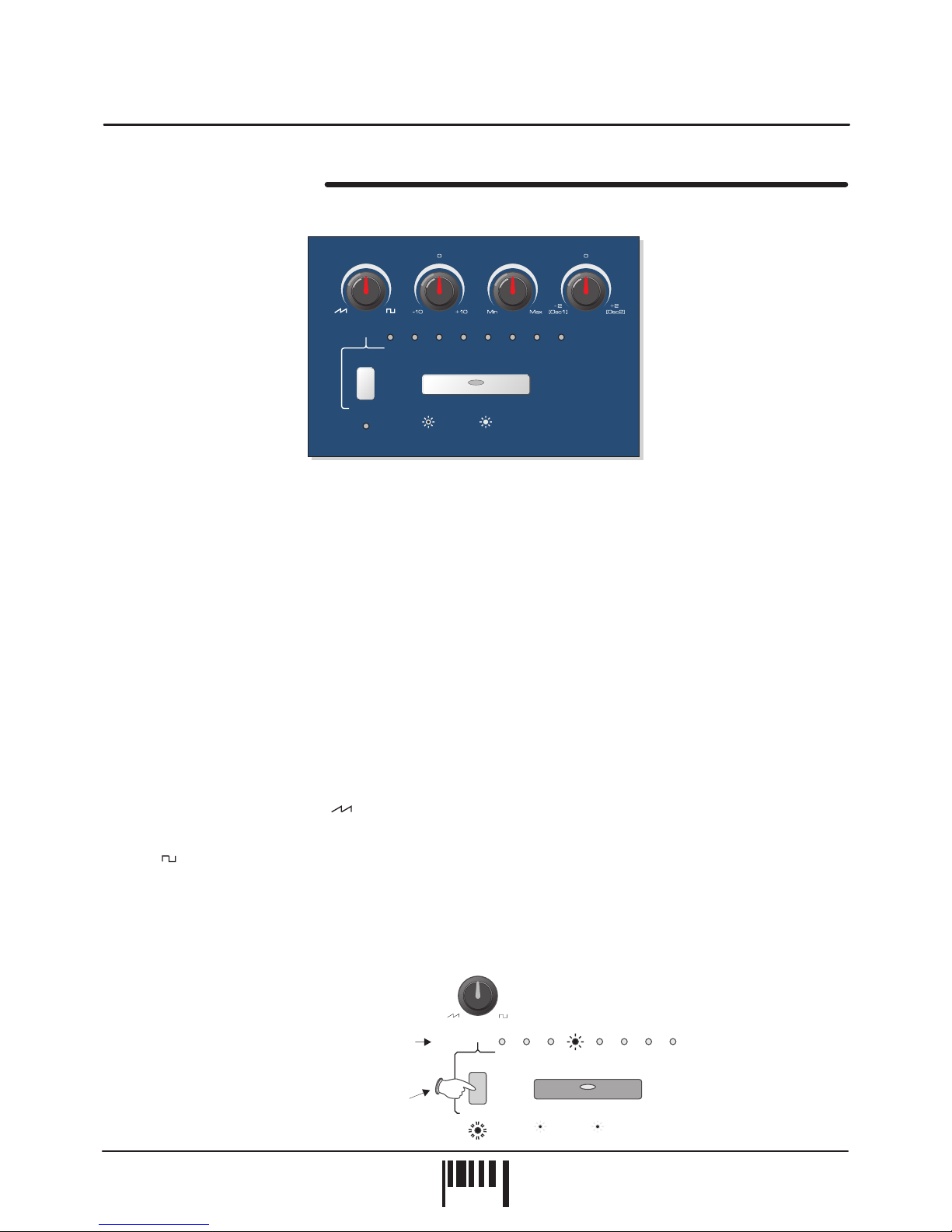
To select the correct MIDI receive channel, press the [MIDI] MENU
button and use the [EDIT] keypad [VALUE +] and [VALUE -] buttons to set the channel of the active PART (as
DARKSTAR XP2 can have up to 5 different sounds/MIDI channels setup in each PROGRAM you may have to
change the MIDI transmit channel on your keyboard a few times to play all the sounds).
To select the factory programs, press the [VOICE/PROGRAM] jog dial knob once and
the display will start to flash the ‘P’ for program. Now simply rotate the [VOICE/PROGRAM] jog dial to scroll up and
down the 64 programs. Whilst the new program data is being loaded the display will flash ‘PL’ for program load -
wait for this to revert to ‘P’ before attempting to audition the new sound.
To hear the sounds, use the front panel [AUDITION] button or connected MIDI keyboard. You can modify the
sounds in real-time by altering the controls in the OSCILLATOR, FILTER, ENVELOPE and LFO sections.
Please read the following “OPERATION” section carefully to fully appreciate the range of features and facilities the
DARKSTAR XP2 8-Voice Synthesizer has to offer.
After connecting DARKSTAR XP2 to your system as detailed on page 5, press IN the rear panel power switch to
turn the power on. The main display will show a welcome message, as shown below:
Afterwards, the last selected program (before power was switched off at the previous session) will be recalled and
displayed as follows:
DARKSTAR XP2 is now ready to use.
CONNECTIONS:
TURNING ON THE POWER:
POWER UP INDICATIONS:
PLAYING THE DEMO:
SETTING THE MIDI RECEIVE CHANNEL:
SELECTING PROGRAMS:
To run the demo sequence, press and the [AUDITION] button, then press the
[MODULATION] menu button once to start playback. To pause the demo simply press the [AUDITION] button once.
hold
PARAMETER
VA L U E
PARAMETER
VA L U E
PARAMETER
VA L U E
Welcome message = dArk StAr
Program 1
6
PAGE
Quick Start
DARKSTAR XP2 - Poly Synth

MASTER VOLUME CONTROL
AUDITION Button
DEMONSTRATION SEQUENCE
Use this control to set the master output level of DARKSTAR XP2. The position of this rotary control will determine
the overall output level from the rear panel [MAIN] left/right, [SUB]1&2audio sockets and also the [PHONES]
monitor output. At the fully anti-clockwise position the output will be zero. As the knob is moved in a clockwise
direction the output level will gradually increase until, at the fully clockwise position the overall volume will be at its
maximum.
This feature allows you to trigger sounds whilst working at the front control panel. There are single note triggers,
chords and patterns to choose from enabling you to try sounds in a number of different ways. Each press of the
[AUDITION] button will trigger the sound and the [VOICE/PROGRAM] jog dial can be used to change the trigger
pattern, as shown in the following examples:
The display will indicate the selections as the jog dial is rotated. The selected trigger type can be stored with the
program.
To play the DARKSTAR XP2 demo sequence, first press and hold down the [AUDITION] button, then press the
[MODULATION] menu button once, as shown in the following example:
To pause the demo at any time simply press the [AUDITION] button once.
audition audition
MASTER
VOLUME
Rotate clockwise
to increase MASTER
VOLUME
Press once to
trigger sound
Press & hold
Playing a sound Changing the AUDITION trigger pattern
Rotate the JOG DIAL
to change the
AUDITION TRIGGER
VOICE/
PROGRAM
[+/up][-/dwn]
To play the demo...
auditionMODULATION
Press and hold
Press once
1
1
2
2
DEMo
[Hold][Press]
OWNERS MANUAL
7
PAGE
Operation

PROGRAMS - Selecting, editing and saving sounds
This section allows you to store all the DARKSTAR XP2 settings in memory for instant recall of your favourite
sounds. The position of every control knob, switch and even the joystick can be memorised in 64 user definable
program memory locations.
Use the [VOICE/PROGRAM] jog dial to select programs from memory, as shown in the
following example:
To edit the selected program simply adjust any of the front panel controls. When the first control or switch
is moved, the [EDIT] indicator will start to flash to indicate ‘EDIT’ mode, as shown in the following example:
If you want to keep the parameter changes made during editing, simply select another program.
SELECTING PROGRAMS:
EDITING:
COMPARE:
don’t
To hear the ORIGINAL settings of the selected program (before it was edited), press the EDIT -
[COMP] button once, as shown below:
You can switch from ‘Edit’ to ‘Compare’ modes as often as you like, simply press the [COMP] button again to jump
from one mode to the other.
PARAMETER
VA L U E
PARAMETER
VA L U E
PARAMETER
VA L U E
PARAMETER
VA L U E
PARAMETER
VA L U E
EDIT
Rotate clockwise or anti-clockwise to change PROGRAM1
3
2
Display shows current PROGRAM number
Display flashes ‘PL’ to indicate
PROGRAM LOADING
...then ‘P 7’ as the new
PROGRAM is loaded in
Flashes to indicate program EDIT mode
VOICE/
PROGRAM
[+/up][-/dwn]
Press the compare [COMP]
button to hear the original
sound
Display changes to ‘C’
to indicate COMPARE mode
MENU
VALUE
VALUE
EDIT
save
COMP
8
PAGE
Operation
DARKSTAR XP2 - Poly Synth

STORE IN EXISTING PROGRAM:
STORE IN ANOTHER PROGRAM:
If you want to store the new settings, they can be saved into the current
program whereby any previous settings will be overwritten. To store the new settings simply press the EDIT [SAVE]
button once, as shown below:
The main display will show 'SAVE' whilst the store operation is carried out.
If you want to keep the existing program the edited setup, you
can overwrite any of the other programs. First, activate COMPARE mode and then use the [VOICE /PROGRAM]
jog dial to select another suitable program location as shown below:
and still save
The 64 factory presets can be re-loaded back into memory at any time.
Press and the
[VOICE/PROGRAM] jog dial knob and then turn power on. The main display will show ‘SURE’ to prompt
confirmation of the load. Press the top [EDIT] button marked ‘VALUE +’’ to confirm the operation (‘LOAD’ appears
briefly in display).
RE-LOAD ALL 64 FACTORY PRESETS: Ensure power is switched OFF. hold down
PART MENU FUNCTIONS
The [PART] menu button at the front of the main panel lets you setup parameters such as POLYPHONY, MIDI
CHANNEL, NOTE RANGE, TRANSPOSE etc for each sound. For full details on the menu list, functions and
settings please see pages 22, 23 and 24.
Loading back all 64 factory presets
PARAMETER
VA L U E
PARAMETER
VA L U E
Press the save [SAVE]
button once to store the
edited sound
Display changes to confirm
SAVE operation
MENU
VALUE
VALUE
EDIT
save
COMP
OWNERS MANUAL
9
PAGE
Operation
PARAMETER
VA L U E
Rotate to select new PROGRAM
When you are sure you want to overwrite the
selected program press SAVE
1
3
2
4
Press the COMPARE button once
Display ‘C’ letter now flashes to indicate
COMPARE SELECT mode
VOICE/
PROGRAM
[+/up][-/dwn]
MENU
MENU
VALUE
VALUE
VALUE
VALUE
EDIT
EDIT
save
save
COMP
COMP

OSCILLATOR SECTION
OSCILLATOR SELECT button
WAVEFORM
This section of DARKSTAR XP2 produces the musical tones which form the basis of subtractive synthesis. There
are two oscillators per ‘voice’ (musical note), each producing audible vibrations to act as a sound source. The
timbre of each oscillator depends on its harmonic content which is determined by the waveform. There are basically
two waveforms available, SAWTOOTH and SQUARE, each with its own specific set of harmonics.
Controls for changing the amount of modulation to the pitch timbre of the oscillators are also included in this
section. These timbral and pitch modulations give the oscillator sound more depth and stimulate musical appeal to
the ear.
This large button switches between oscillator 1 and 2. When the indicator is OFF, oscillator 1 will be selected.
When the indicator is ON, oscillator 2 will be selected.
This control has two functions determined by the [SHIFT] button.
When the [SHIFT] function is (SHIFT LED Off) this control sets the selected oscillator’s waveform.
At the fully anti-clockwise position ( ) the waveform will be shaped like a SAWTOOTH. This waveform contains
every harmonic in decreasing volume and produces a very rich sound. As the control is moved in a clockwise
direction the shape progressively changes, becoming more and more ‘squared-off’ until, at the fully clockwise
position ( ) the shape will be a SQUARE or ‘pulse’ waveform. As a pure square wave (max and min values equal)
the harmonic content will be all the odd-numbered harmonics in decreasing volume which gives the sound a hollow
or ‘woody’ timbre. The width of the pulse can also be altered by the [PULSE WIDTH] knob to make the sound
thinner.
When the [SHIFT] function is selected (SHIFT LED Flashing) this control sets the amount of oscillator 2 pitch
offset. This detune setting is calibrated in semitones with the eight indicators labelled [OSC 2 SEMITONE OFFSET]
showing the value, as in the following example:
(OSC 2 PITCH)
NOT selected ,
,
Example:
Oscillator 2 pitch offset =
12 semitones (1 octave)
Press once
before changing
the setting
SHIFT
OSC 2 SEMITONE OFFSET
1716 19 2412750
PITCH MODWAVEFORM
WAVEFORM
PWM ring mod osc mix
DETUNEPULSE WIDTH
Oscillators
Osc 1
Osc 2
OSC 2 PITCH
SHIFT
OSC 2 SEMITONE OFFSET
1716 19 2412750
Oscillators
Osc 1
Osc 2
OSC 2 PITCH
10
PAGE
Operation
DARKSTAR XP2 - Poly Synth

PITCH MOD
PULSE WIDTH
DETUNE
OSCILLATOR MENU
(PWM)
[RING MOD)
[OSC MIX)
This control has two functions determined by the [SHIFT] button.
When the [SHIFT] function is (SHIFT LED Off) this control sets the amount of pitch modulation to
the selected oscillator. At the 12 o’clock position there will be no pitch modulation applied. As the knob is moved in
an anti-clockwise direction the pitch modulation will become negative, first falling then rising. At the fully anti-
clockwise position the modulation will be at its maximum negative depth. As the knob is moved in a clockwise
direction from the centre position, the pitch modulation will become positive, first rising then falling. At the fully
clockwise position the modulation will be at its maximum positive depth. See [OSCILLATOR] menu section below
for further details on the pitch modulation source.
When the [SHIFT] function is selected (SHIFT LED Flashing) this control sets the amount of pulse width
modulation or PWM for the selected oscillator when its [WAVEFORM] is set to SQUARE ( ). The PWM
SOURCE can be set to LFO1, LFO2, ENV1 or ENV2 (see [OSCILLATOR] menu) with negative and positive
modulations available. At the 12 o’clock position there will be no PWM. As the knob is moved in an anti-clockwise
direction the variation in the pulse width will become more and more pronounced in a negative manner. As the
knob is moved in a clockwise direction the variation in the pulse width will become more and more pronounced in a
positive manner.
This control has two functions determined by the [SHIFT] button.
When the [SHIFT] function is (SHIFT LED Off) this control sets the actual width of the pulse. At the
fully anti-clockwise position the fundamental will be at its minimum producing an extremely thin sound. As the knob
is moved in a clockwise direction the pulse width gets wider, with progressively less high harmonics being added
giving the sound a fuller timbre. At the fully clockwise position the minimum and maximum values of the pulse width
will be equal.
When the [SHIFT] function is selected (SHIFT LED Flashing) this control sets the amount of ring modulation
applied to the sound. Ring modulation occurs when the two sound sources are multiplied together and this gives
the resultant sound a harder, over-driven edge. At the fully anti-clockwise position the ring modulation will be at its
minimum. As the knob is moved in a clockwise direction the ring modulation gradually increases until, at the fully
clockwise position the ring modulation effect will be at its maximum.
This control has two functions determined by the [SHIFT] button.
When the [SHIFT] function is (SHIFT LED Off) this control sets the fine tuning for each oscillator. At
the 12 o’clock position the oscillators tuning will be unaffected. As the knob is moved in an anti-clockwise direction
the oscillators tuning will become more ‘Flat’, with a total negative detune of - 2 semitones available at the fully anti-
clockwise position. As the knob is moved in a clockwise direction the oscillators tuning will become more ‘Sharp’,
with a total positive detune of + 2 semitones available at the fully clockwise position. Small variations in the
oscillators relative tuning will fatten up a sound giving it a rich texture. Larger amounts of detuning create a more
extreme effect.
When the [SHIFT] function is selected (SHIFT LED Flashing) this control sets the mix level between the oscillators.
At the 12 o’clock position the level of both oscillators will be equal. As the knob is moved in an anti-clockwise
direction the level of oscillator 2 will begin to decrease until, at the fully anti-clockwise position, only oscillator 1 can
be heard. As the knob is moved in a clockwise direction the level of oscillator 1 will begin to decrease until, at the
fully clockwise position, only oscillator 2 can be heard.
This section contains the remaining functions for the oscillators. To access these settings, press the MENU button
labelled [OSCILLATORS], as shown in the following example:
NOT selected ,
,
NOT selected ,
,
NOT selected ,
,
OWNERS MANUAL
11
PAGE
Operation

The indicator in the [OSCILLATOR] button will light and the main display will now alternate between the first function
and its current value, as shown below:
There are 4 functions in the oscillator menu with multiple settings as detailed in the following paragraphs.
This function allows you to select the oscillator pitch modulation source. The
selections are:
The output of envelope 1 will modulate the oscillator pitch.
The output of envelope 2 will modulate the oscillator pitch.
The output of LFO1 will modulate the oscillator pitch.
The output of LFO2 will modulate the oscillator pitch.
This function allows you to select the oscillator pulse width modulation source.
The selections are:
The output of envelope 1 will modulate the oscillator pulse width.
The output of envelope 2 will modulate the oscillator pulse width.
The output of LFO1 will modulate the oscillator pulse width.
The output of LFO2 will modulate the oscillator pulse width.
This function allows you to select the sound source for OSCILLATOR 2. The selections are:
This oscillator contains the full range of frequencies.
This oscillator is formed from a limited band of frequencies.
This oscillator is based on a pure sine wave.
PINK noise has the higher frequencies reduced.
WHITE noise and has all frequencies at an equal level.
BLUE noise has the lower frequencies reduced.
You can switch off all the internal sound generators for oscillator 2 and instead use the rear
panel connectors marked [EXTERNAL INPUTS1-2]toprocess any MIDI driven external sound source through the
filter and envelope sections. See page 35 for further details.
This function synchronises oscillator 2 with oscillator 1. The oscillator 2 waveform will now
restart its cycle each time oscillator 1 starts its own cycle. The result of this keeps the pitch of both oscillators
identical making a distinct change to the timbre. For the best results use envelope 2 to try and move the pitch of
oscillator 2. The pitch cannot change but you will hear timbral changes to the sound with vocal characteristics.
The selections are:
The waveforms of oscillators1&2will be free-running
The waveforms of oscillators1&2will be synchronised
1. Pitch Modulation Source:
Envelope1:
Envelope 2:
LFO1:
LFO2:
2. Pulse Width Modulation source:
Envelope1:
Envelope 2:
LFO1:
LFO2:
3. Oscillator 2 source:
Type 1(normal oscillator):
Type 2(Formant style oscillator):
Sine (Sine Wave oscillator):
Noise1(Pink):
Noise 2(White):
Noise 3(Blue):
External Input1&2:
4. Oscillator Sync:
OFF:
ON:
PARAMETER
VA L U E
PARAMETER
VA L U E
First selection =
Envelope 1
Function =
Pitch Modulation
source
Display alternates
between
12
PAGE
Operation
DARKSTAR XP2 - Poly Synth
MENUS
OSCILLATORS auditionMODULATIONMIDILFOFILTER PORTA TRIGGERPART
MENU
VALUE
VALUE
EDIT
save
COMP
/

To change the current oscillator menu setting, use the [EDIT] keypad [VALUE +] and [VALUE - ] buttons as shown
in the following example:
To select a different menu function, use the [MENU UP] and [MENU DOWN] buttons. To EXIT oscillator menu
mode, simply press the [OSCILLATOR] MENU button and check that the indicator goes out.
This section of DARKSTAR XP2 is used to shape the sound over a period of time with two envelopes available.
The first envelope is fixed to amplitude (or volume) and decides how quickly the sound starts, sustains and then
fades away. The second envelope can be used to control the filter frequency, pulse width or pitch modulations to
alter the character of the sound.
This large button switches between envelope 1 and 2. When the indicator is OFF, envelope 1 will be selected.
When the indicator is ON, envelope 2 will be selected.
ENVELOPE SECTION
ENVELOPE SELECT button
PARAMETER
VA L U E
PARAMETER
VA L U E
New Pitch Mod Source =
LFO2
Press 3 times
to change value
Press once to exit
oscillator menu mode
Function =
Pitch Modulation
source
Display alternates
between
Press the UP and
DOWN buttons to
select MENU functions
PANNINGLEVEL PORTAMENTOTREMOLO
env 1
SHIFT
Envelopes
Env 2
VELOCITY LEVEL
54673210
DECAYATTACK RELEASESUSTAIN
Max
OffOff
--
++
MaxMax MaxMinMin
VELOCITY
Min Min
OWNERS MANUAL
13
PAGE
Operation
MENU
MENU
VALUE
VALUE
VALUE
VALUE
EDIT
EDIT
save
save
COMP
COMP
OSCILLATORS
OSCILLATORS
MENU
VALUE
VALUE
EDIT
save
COMP
OSCILLATORS

ATTACK
DECAY
SUSTAIN
RELEASE
This control sets the time period for the envelope to reach its maximum after a note is played. At the fully anti-
clockwise position the response is virtually instantaneous giving a percussive edge to the sound. As the knob is
moved in a clockwise direction the time to reach maximum gradually increases giving a softer start to the sound. At
the fully clockwise position the attack time will be at its maximum.
This control sets the rate at which the envelope falls to the [SUSTAIN] level after the maximum [ATTACK] level has
been reached. At the fully anti-clockwise position the response is virtually instantaneous. As the knob is moved in a
clockwise direction the decay duration gradually increases until, at the fully clockwise position the decay time will
be at its maximum.
This control sets the level of the envelope after the decay element is completed and until the note is released. At
the fully anti-clockwise position the envelope will continue to decay to zero without interruption. As the knob is
moved in a clockwise direction the level at which the decay ends gradually increases until, at the fully clockwise
position the sustain level will be at its maximum.
This control has two functions determined by the [SHIFT] button.
When the [SHIFT] function is (SHIFT LED Off) this control sets the time taken for the sustain level to
reach zero once the note has been released. At the fully anti-clockwise position the response is virtually
instantaneous giving an abrupt end to the sound. As the knob is moved in a clockwise direction the release time
gradually increases resulting in a softer, more natural end to the sound. At the fully clockwise position the release
time will be at its maximum.
When the [SHIFT] function is selected (SHIFT LED Flashing) this control sets how much the selected envelope is
affected by the velocity level. Firmly struck notes will open the envelope to its maximum level whilst softer strokes
will produce a lesser result, dependent on the velocity setting. The eight VELOCITY LEVEL indicators show the
velocity setting for the selected envelope. To change the setting, first press the [SHIFT] button and then move the
[VELOCITY] knob. The indicators will show the value, as shown in the following example:
At the fully anti-clockwise position [indicator 0] there will be no velocity effect, with soft and hard notes each
producing the same, maximum result. As the knob is moved in a clockwise direction [indicators 1 to6]the
envelope will open less and less when softer notes are played until, at the fully clockwise position [indicator 7] the
softest notes will not open the envelope at all. On envelope 1 this maximum setting will make soft notes sound very
quiet whilst on envelope 2 this will result in much less pitch, pulse width or filter modulation.
(VELOCITY)
NOT selected ,
,
Press once
before changing
the setting
Example: Envelope 1 velocity setting = 5
14
PAGE
Operation
DARKSTAR XP2 - Poly Synth
env 1
SHIFT
Envelopes
Env 2
VELOCITY LEVEL
54673210
RELEASE
Max
VELOCITY
Min

LFO SECTION
LFO SELECT button
SPEED
DELAY
This section of DARKSTAR XP2 features 2 LFOs (Low Frequency Oscillators) which make regular electronic
variations, too low to be heard when converted into audio vibrations. They can be used independently to alter
elements of the sound by adding vibrato or changes to the harmonic content.
This large button switches between LFO1 and 2. When the indicator is OFF, LFO1 will be selected. When the
indicator is ON, LFO2 will be selected.
This control has two functions determined by the [SHIFT] button.
When the [SHIFT] function is (SHIFT LED Off) this control sets the rate of the selected LFO. At the
fully anti-clockwise position the speed will be at its slowest. As the knob is moved in a clockwise direction the speed
gradually increases until, at the fully clockwise position the LFO speed will be at its maximum.
When the [SHIFT] function is selected (SHIFT LED Flashing) this control is used to synchronise the LFO with an
external MIDI clock. The trigger rate can be set to a range of values from 1/8th beat to 4 bars in duration. At the
fully anti-clockwise position the LFO to MIDI synchronisation feature will be OFF. As the knob is moved in a
clockwise direction the trigger rate becomes less frequent until, at the fully clockwise position the LFO will cycle
once every 4 bars.
To view the setting, press the [SHIFT] button. The main display will now show the current value, as shown in the
following example:
To change the setting move the [MIDI CLOCK] knob. The main display will show the new value.
Range = OFF, 1/8bt,1/6bt, 1/4bt, 1/3bt, 1/2bt, 2/3bt, 3/4bt, 1bt, 2bt, 3bt, 1bar, 1.5 bars, 2 bars, 3 bars, 4 bars.
This control sets the time taken for the LFO to be introduced after a note is struck. At the fully anti-clockwise
position the LFO will start immediately. As the knob is moved in a clockwise direction the delay period before the
LFO starts will gradually increase until, at the fully clockwise position the delay time will be at its maximum.
NOT selected ,
,
PULSESINE SAMPLE RANDOMSQUARETRIRAMP
DELAYSPEED
(MIDI CLOCK)
SHAPE
LFO 1
SHIFT
MaxMax
LFO’s
LFO 2
MinMin
LFO SHAPE
LFO to MIDI clock
trigger rate = every ½ beat
PARAMETER
VA L U E
OWNERS MANUAL
15
PAGE
Operation

SHAPE
LFO MENU
This control selects the waveform which determines the contour of the LFO modulation. There are 7 waveforms to
choose from as follows:
[]
[]
[]
[]
[]
[]
[]
This section contains the remaining functions for the LFOs. To access the LFO settings, press the MENU button
labelled [LFO], as shown in the following example:
The indicator in the [LFO] button will light and the main display will now alternate between the first function and its
current value, as shown below:
The first function in the LFO menu is:
This function sets the LFOs to start from the beginning of the selected waveform each
time a note is played. The selections are:
The waveforms of all LFOs are synchronised but will be free running.
The waveforms of all LFOs are synchronised but will re-start from the beginning of the selected waveshape
each time a note is played.
To exit LFO menu mode, simply press the [LFO] MENU button and check that the indicator goes out.
RAMP
TRI
SQUARE
SINE
PULSE
SAMPLE&HOLD
RANDOM
1. Key Synchronisation:
Off:
On:
LFO 1 waveshape = Sine
SHAPE
PARAMETER
VA L U E
PARAMETER
VA L U E
Setting = ON
Function =
Key Synchronisation Display alternates
between
Press once to exit
LFO menu mode
16
PAGE
Operation
DARKSTAR XP2 - Poly Synth
PULSESINE SAMPLE RANDOMSQUARETRIRAMP
LFO 1
LFO’s
LFO 2
LFO SHAPE
MENUS
OSCILLATORS auditionMODULATIONMIDILFO
LFO
FILTER
FILTER
PORTA TRIGGERPART
PART
MENU
VALUE
VALUE
EDIT
save
COMP
/

FILTER SECTION
FILTER SELECT button
FREQUENCY
This section of DARKSTAR XP2 features a classic 12dB per octave filter which, in subtractive synthesis, is used to
remove unwanted frequencies. There are three different types of filter to choose from, LOW PASS, BAND PASS
and HIGH PASS or the filter can be totally switched off.
This large button switches the filter on and off. When the indicator is OFF the filter will be bypassed. When the
indicator is ON the filter will be active.
This control has two functions determined by the [SHIFT] button.
When the [SHIFT] function is (SHIFT LED Off) this control sets the basic cut-off frequency of the
filter. The affect this control has on the sound depends on the type of filter selected (low, band or high-pass), as
detailed in the following paragraph.
When the [SHIFT] function is selected (SHIFT LED Flashing) this control selects the FILTER TYPE. The four
indicators labelled FILTER TYPE show the current setting at all times. To change the filter type, first press the
[SHIFT] button and then move the [FILTER TYPE] knob. The indicators will show the setting as shown in the
following example:
At or near the fully anti-clockwise position the LOW PASS filter type will be selected:
This type of filter allows the low frequency elements to pass whilst reducing the higher frequencies as
the FREQUENCY control is moved .
(FILTER TYPE)
NOT selected ,
,
anti-clockwise
LOW-PASS:
FILTER TYPE RES MOD SOURCE
ENV1 ENV2HI LFO1 LFO2BANDLOOFF
RESONANCEFREQUENCY
RES MODFILTER TYPE
LFO 2 MOD
ENV MOD
Filter
Max
Filter Off
Filter On
SHIFT
Min
0
+10-10
(0)
(+10)(-10)
Press once
before changing
the setting
Example: Filter type = High Pass
OWNERS MANUAL
17
PAGE
Operation
FILTER TYPE RES MOD SOURCE
ENV1 ENV2HI LFO1 LFO2BANDLOOFF
FREQUENCY
FILTER TYPE
Filter
Max
Filter Off Filter On
SHIFT
Min

About the 12 o’clock position the BAND PASS filter type will be selected:
This type of filter allows a limited band of frequencies to pass whilst reducing the remaining high and
low frequencies, the filtered frequency band being set by the position of the FREQUENCY control.
At or near the fully clockwise position the HIGH PASS filter type will be selected:
This type of filter allows the high frequency elements to pass whilst reducing the lower frequencies as
the FREQUENCY control is moved
This control has two functions determined by the [SHIFT] button.
When the [SHIFT] function is (SHIFT LED Off) this control sets the boost level of the frequencies
around the cut-off point as set by the FREQUENCY control. At the fully anti-clockwise position there is no boost. As
the control is moved in a clockwise direction the frequencies will be gradually increased until, at the fully clockwise
position, the resonance will reach self-oscillation producing a new pitched element similar to acoustic feedback.
When the [SHIFT] function is selected (SHIFT LED Flashing) this control sets the level of resonance modulation.
At the 12 o’clock position there will be no resonance modulation. As the knob is moved in an anti-clockwise
direction the amount of resonance modulation will become more and more pronounced in a negative manner. As
the knob is moved in a clockwise direction the amount of resonance modulation will become more and more
pronounced in a positive manner - see [FILTER] MENU below for details on selecting the resonance modulation
source.
This control has two functions determined by the [SHIFT] button.
When the [SHIFT] function is (SHIFT LED Off) this control sets the amount of change (depth) of the
cut-off frequency as set by the FREQUENCY control. At the 12 o’clock position there will be no change to the filter
cut-off frequency. As the control is moved in an anti-clockwise direction the filter will be increasingly opened by the
audio modulation in a negative manner. As the knob is moved in a clockwise direction from the centre position the
filter will be increasingly opened by the audio modulation in a positive manner.
When the [SHIFT] function is selected (SHIFT LED Flashing) this control sets the level of LFO 2 modulation. At the
12 o’clock position there will be no LFO 2 modulation applied. As the knob is moved in an anti-clockwise direction
LFO 2 modulation will be applied more and more in a negative manner. As the knob is moved in a clockwise
direction from the centre position LFO 2 modulation will be applied more and more in a positive manner.
This section contains the remaining functions for the filter. To access these settings, first press the MENU button
labelled [FILTER], as shown in the following example:
The indicator in the [FILTER] button will light and the main display will now alternate between the first function and
its current value, as shown below:
BAND-PASS:
HIGH-PASS:
clockwise.
NOT selected ,
,
NOT selected ,
,
RESONANCE
ENV MOD
FILTER MENU
(RES MOD)
(LFO 2 MOD)
PARAMETER
VA L U E
PARAMETER
VA L U E
Setting = 50%
Function =
Keyboard tracking
Display alternates
between
18
PAGE
Operation
DARKSTAR XP2 - Poly Synth
MENUS
OSCILLATORS auditionMODULATIONMIDILFOFILTER PORTA TRIGGERPART
MENU
VALUE
VALUE
EDIT
save
COMP
/

The functions in the filter menu are:
This function lets you choose whether the filter has the same effect across the entire note
range or has a different effect on the lower and higher notes. This function is applied as a percentage of note
change. The selections are:
The keyboard tracking is off and so the filter’s effect will be the same across all notes.
The keyboard tracking is now on. The filter will now open increasingly less for the low notes
and more for the high notes until the effect is at its maximum when the level is set to 150%. There are two negative
settings included, where the filter will open less for the notes and more for the notes.
This function allows you to select the filter resonance modulation source. The
selections are:
The output of envelope 1 will modulate the filter resonance
The output of envelope 2 will modulate the filter resonance
The output of LFO1 will modulate the filter resonance
The output of LFO2 will modulate the filter resonance
To select a different menu function, use the [MENU UP] and [MENU DOWN] buttons.
To EXIT filter menu mode, simply press the [FILTER] MENU button and check that the indicator goes out.
The centrally mounted joystick offers huge creative potential. You can assign parameters such as filter frequency
/resonance to the joystick for added creative expression and ‘on-the-fly’ editing of two elements simultaneously.
The joystick can also be switched off to avoid accidental voice editing if the joystick is nudged during a
performance. The joystick operates in parallel to the labelled front panel controls.
For a list of functions and how to change the joystick settings please see the UTILITY section on page 30.
1. Keyboard tracking:
0FF:
25, 50, 100, 150%:
- 25 and -50
2. Resonance Modulation Source:
Envelope1:
Envelope 2:
LFO1:
LFO2:
high low
JOYSTICK Control
MENU
VALUE
VALUE
EDIT
save
COMP
OSCILLATORS
Press the UP and
DOWN buttons to
select MENU functions PARAMETER
VA L U E
New Function =
Filter Resonance mod source
Press once to exit
FILTER menu mode
OWNERS MANUAL
19
PAGE
Operation
OSCILLATORS LFOFILTER
JOYSTICK
Y
X

MULTITIMBRAL PARTS
This section of DARKSTAR XP2 lets you to set up to five different sound sources on each program for multiple
voice generation. You can specify the number of voices, note range, transposition, MIDI channel and other
parameters for each individual sound so that for instance, a fat dirty bass sound can be played right alongside a
warm string sound simultaneously on the same keyboard. When connected to a MIDI sequencer you can really get
the maximum sound generating power out of DARKSTAR XP2 by setting each PART to different MIDI channels for
complex synthesizer layering.
The five [PART SELECT] buttons grouped beneath the joystick mixer are used to select the active PART for editing.
When a [PART] button indicator is on, any changes to the front panel controls and/or MENU functions will be
applied to that PART only.
To select another PART, press the required [PART] button as shown in the following example:
This feature allows you to transfer all parameter data (except the polyphony setting) from one PART
to another at the press of a button. As an example, if you create a great sound on PART 1, you can easily copy this
sound in its entirety to any number of other PARTS in the same program. By using the same MIDI channel and
note ranges for all PARTS the oscillators will sound simultaneously (in ‘unison’) when a note is struck. PART
copying is also useful for making new sounds from the basis of an original idea.
To copy a PART, first the currently selected [PART] button (LED will flash), as shown in the
following example:
Now press the [PART] button which coincides with the desired destination, as shown below:
After copying, the original PART will still be selected. You can repeat this operation for other PARTS until the
polyphony is used up. Remember to save the program after editing has been completed.
PART COPY:
press and hold down
21
PART SELECT
354
Current PART = PART 1
20
PAGE
Operation
DARKSTAR XP2 - Poly Synth
21
PART SELECT
354
New PART = PART 4
2
2
1
1
PART SELECT
PART SELECT
3
3
5
5
4
4
Press and hold current PART button
PART indicator flashes
Press = PART 1 copied to PART 5
Table of contents
Other Red Sound Synthesizer manuals