LZX Industries Vidiot User manual

User Manual

Vidiot
Conceptual Design by Dan Bucciano
Circuit Design by Dan Bucciano & Lars Larsen
Interface & Enclosure Design by Lars Larsen
Printed Circuit Board Design by Jonah Lange
Interface Illustrations by Dave Larsen
Acknowledgments
This device is covered by our manufacturer warranty for one year following the date of
manufacture. This warranty covers any defect in the manufacturing of this product., such
as assembly errors or faulty components. This warranty does not cover any damage or
malfunction caused by incorrect use – such as, but not limited to, power cables connected
backwards, excessive voltage levels, or exposure to extreme temperature or moisture
levels. The warranty covers replacement or repair, as decided by the manufacturer. LZX
Industries implies and accepts no responsibility for harm to person or apparatus caused
through operation of this product. Please contact customer service via our website at
www.lzxindustries.net for instructions on returning the product.
LZX Industries LLC
814 SE 14th Ave
Portland, OR 97214
+1 (503) 770-0726
www.lzxindustries.net
Written by Lars Larsen
Layout & Illustration by Dave Larsen
First Printing, December 2017
User Manual
Manufactured in Portland, Oregon USA by
Darkplace Manufacturing & Distribution LLC
This device complies with Part 15 of the FCC Rules. Operation is subject to the following
two conditions: (1) this device may not cause harmful interference, and (2) this device
must accept any interference received, including interference that may cause undesired
operation.

Table of Contents
Welcome
Video Arst Page 1
The Paern
Generator Page 7
The
Video Input Page 13
How
To Play Page 5
Next
Steps Page 15
The
Colorizer Page 11
Basic
Setup Page 3
The Luma
Processor Page 9
Exploratory
Exercises Page 14

In 2009, analog television broadcasts
went off the air forever in the United
States. In the same year, LZX was born.
We knew our mission to preserve and
empower the tradition of analog video
art instruments would be difficult, but
that a potential revolution lay in wait.
And here you are, an artist in a new age
of video art, holding an impossible
instrument.
Vidiot would have cost a fortune in the
1970s. Strictly the domain of television
broadcast studios and universities.
That’s why engineers like our design
partner Dan Bucciano
had difficulty
making video
synthesizers
a reality for the
common artist...
until now!
At 14 years old, Dan began his lifelong
journey with video art by experimenting
with broken TV sets, creating visuals to
entertain himself and his friends.
This fascination drew him to New York
City in the 1970’s to become a player in
the eclectic community of artist-
engineers responsible for some of the
world’s first analog video synths. As a
young technician, he worked for video
synth pioneers such as Eric Siegel and
Bill Etra.
Releasing his own video instrument has
been a life long ambition, now fulfilled
with Vidiot. Dan currently lives in Maine
on an 11-acre plot of woods where he
creates video art and teaches
workshops about essential oils.
Meet Dan Bucciano
1
Welcome Video Arst

After working through this User Manual,
you should be able to:
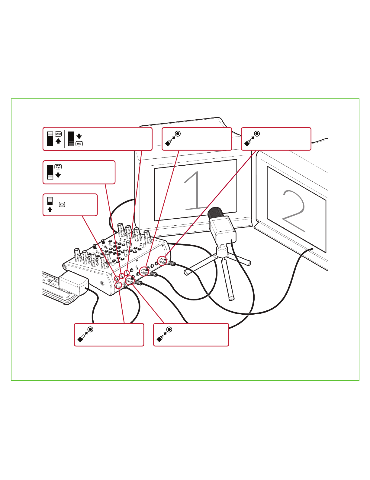
- Connect Vidiot to televisions, cameras,
and other external video devices.
- Understand and use Vidiot’s front and
rear interfaces, including bias controls,
attenuators, switches and I/O jacks.
- Expand Vidiot’s capabilities with
EuroRack synthesizer modules.
- Engage with the user community.
Let’s start on the next page by getting
your video art studio set up!
Learning ObjecvesWhy Analog Video?
The analog video signal is one of the
20th century’s most exciting
innovations. It is inherently both
artificial and organic.
Artificial in the sense that it is a process
divorced from the natural world of color
and light as perceived by the cones
inside human eyeballs.
Organic in the sense that it is a realtime,
continous voltage intended to drive the
position and brightness of a cathode
ray tube, and subject to all the little
idiosyncrasies thereof.
A digital image is frozen. A precise grid
of numerical values to be read, modified
and rewritten. An analog image is
always in motion, redrawing itself with
slight differences with each recursion.
Working with digital video is like being
a sculptor or a surgeon. Working with
analog video is like piloting a vehicle --
you’ve gotta be along for the ride!
Both types of imagemaking have their
different creative uses and strengths,
but to lose analog video as an artistic
medium would be a tragic loss. 2

Everything you need to immediately
begin using Vidiot is in the box, except
for one thing: A display. For your
display, you can use any kind of
television or projector with a Composite
video input. Look for the yellow RCA
jack labeled Composite, or just Video,
and connect to it to using the included
video cable.
The diagram on the opposing page
demonstrates Vidiot’s default studio
configuration, although there are
endless possibilities. If you don’t have
two displays and a camera, don’t worry.
Only the connection to a single display
from either the Colorizer or Luma
Processor outputs is required.
Basic Setup
3
NTSC and PAL are two different
standards for analog video. NTSC has a
higher frame rate, but less vertical
resolution. PAL has a lower frame rate,
but more vertical resolution.
If you are in the United States, chances
are any gear you use will be NTSC. If
you are in the EU or Australia, your gear
will be PAL.
NTSC vs. PAL

Luma processor
out connects to
video display #1.
Colorizer out
connects to
video display #2.
NTSC/PAL camera
connects to video
input.
Power switch
( ) set to
ON position.
Format set to NTSC or
PAL, matching external
gear used.
Loop switch set
to down position.
Included power
adapter plugged
into DC input.
4

Video synthesizers are experimental instruments.
Freeform experimentation can be intimidating,
especially without prior experience using audio
synthesizers and CV (Control Voltage) signals to
modulate parameters.
Don’t worry, you have plenty of time to learn all the
details. We recommend you start by just turning it
on and spending time turning knobs, flipping
switches, and having fun. After that, return to this
section to learn more about what is going on. Then,
explore the next sections when you want the
answers to specific questions
related to Vidiot’s
functions and
features.
How To Play
5
The rotary switches select
preset modulation paths. No
patching required.
Select modulaon presets.
When you patch to an input,
you will override the preset.
Any output jack can go to any
input jack... experiment!
Patch outputs to inputs.
Outputs are filled.
Inputs are outlined.
Follow the
arrows!

The bottom knobs adjust the level of the control voltage
input signal.
Change the depth of modulaon.
6
0% 25% 50% 75% 100%
To the left, control voltages
are positive. To the right,
inverted.
Invert the modulaon.
Normal Inverted
The top knobs adjust an offset voltage which is added to the
control voltage signal.
Manipulate funcons manually.
+50% +100%0%-50%-100%
Binary functions, such as
Solarize and Negative, turn on
when the input signal is above
50%, and turn off below.
Use binary funcons and keys.
ON
OFF
50%
The two key generators create
binary control signals with
variable threshold values.

The Paern Generator
7
Horizontal
Triangle Vercal
Sine
Horizontal
Sine Noise
Circle Diamond Hatch
Vercal
Triangle
Audio Envelope
Horizontal
Square Vercal
Square
Symmetry
Circle & Diamond shapes only.
Sync
On (Stable) Off (Scrolling)
Patch to and then
adjust and .
Frequency Modulation

Power Switch
Video Mode
On/Off
Horizontal Sync Switch
LED Indicator
1V DC
LED Indicator
On/Off
Vercal Sync Switch
LED Indicator
Vercal Sync In
Horizontal Sine Out
Vercal Sine Out
Horizontal Square Out
Horizontal CV In
1V DC
1V DC
1V DC
Horizontal Triangle Out
1V DC
Vercal Square Out
Horizontal Frequency 10KHz - 1MHz
Pos. / Neg.
Horizontal CV Mode
Vercal Frequency 50Hz - 5KHz
Vercal CV Level 0% - 100%
Vercal CV In
Horizontal - Vertical
Symmetry Control
Pos. / Neg.
Vercal CV Mode
1V DC
Vercal Triangle Out
Noise Out
Audio Envelope Out
1V DC
1V DC
Circle Out
Diamond Out
1V DC
1V DC
Hatch Out 1V DC
Stereo Audio In Line Level
Audio Filter Switch HP
8
Horizontal Sync In
LPOFF
Vidiot’s Pattern Generator creates abstract pattern elements in real time with analog circuits. There is a
horizontal oscillator, a vertical oscillator, a noise generator, an audio envelope follower, and three shape
mixes. You can route these elements to the Luma Processor and Colorizer via the modulation selection
switches in those sections, or directly with patch cables.
Up to +/-10V DC
Up to +/-10V DC
Horizontal CV Level 0% - 100%

The Luma Processor
9
Brightness
Contrast
Detail
Solarize
Luma Negave
Key 1
Set or to and
adjust .
Using Key Generator 1

1V DC
Luma Out
75R Video
Luma Video Out
Brightness Control
Up to +/-10V DC
Brightness CV In
0% - 100%
Key 1 Threshold
Video
Noise
Hatch Horizontal Triangle
Circle Diamond
Modulaon Select Audio
Off On Key 1
Luma Neg. Mode
0.5V Threshold
Luma Neg. Gate In
Pos. / Neg.
Brightness CV Mode
+/- 100%
Brightness CV Level 0% - 100%
Contrast Control
Up to +/-10V DC
Contrast CV In
Pos. / Neg.
Contrast CV Mode
+/-100%
Contrast CV Level 0% - 100%
Detail Control Up to +/-10V DC
Detail CV In
Pos. / Neg.
Detail CV Mode
0% to 100%
Detail CV Level 0% to 100%
Vertical Triangle
Off On Key 1
Solarize Mode
0.5V Threshold
Solarize Gate In
10
0 - 1V DC
Key 1 Source In
Vidiot’s Luma Processor is located on the left hand side of the instrument. It’s purpose is to change the
properties of monochromatic (black and white only) video signals. Video from the external video input
is sent into it as the source image. The Luma Processor has a dedicated video output which can be
displayed, or the Colorizer can select its output as a modulation source directly.
“I first fell in love with solarization as a film effect in the late 60's while developing B&W photographic
prints. Even causing it was entertaining: you quickly turn white light on and off while the print is in the
developer tank. This causes a chemical reaction to occur which turns the lighter areas in the print to
negative, but what makes it look so dynamic is the outline between the positive and negative areas.
When I tried to create the same effect with video years later, I first tried full-wave rectifying the video
signal. I got solarization but soon realized that simply full-wave rectifying the video signal won't give
you that beautiful outline, so I set out to create circuitry that would. That circuitry is what's used in
Vidiot to give the solarization that special look. And Vidiot also lets you get inverted solarization,
something my original circuitry didn't.” - Dan Bucciano

1V DC
Red Out
1V DC
Green Out
1V DC
Blue Out
75R Video
Color Video Out
0.5V Threshold
Color Neg. Gate In
Video
Noise Hatch
Vertical Sine
Circle Diamond
Modulaon Select Audio
Luma Processor
Off On Key 2
Color Neg. Mode
0.5V Threshold
RGB Neg. Gate In
Red Green Blue
RGB Neg. Mode
Up to +/-10V DC
Red CV In
Pos. / Neg.
Red CV Mode
0% - 100%
Red CV Level
Up to +/-10V DC
Green CV In
Pos. / Neg.
Green CV Mode
0% - 100%
Green CV Level
Up to +/-10V DC
Blue CV In
Pos. / Neg.
Blue CV Mode
0% to 100%
Blue CV Level
0% - 100%
Key 2 Threshold
0 - 1V DC
Key 2 Source In
Red Control
+/-100%
Green Control
+/-100%
Blue Control
+/-100%
The Colorizer
11

12
The Colorizer is a staple of early analog video art, as it allowed the artist to take a monochromatic
image and map its grayscale regions into psychedelic rainbows of red, green and blue. Vidiot’s
Colorizer is deceptively powerful, due to the high gain on its input channels. This functionality allows
soft key processing right at the inputs, allowing the artist a great degree of control over separating and
blending the different color bands.
Red
Green
Blue
Color Negave
RGB Negave
Key 2
The Colorizer produces beautiful analog gradients with just a single source
(selected by the modulation switch) but don’t forget to try patching
outputs from the Pattern Generator directly to the inputs of the Colorizer
to override the preset modulation source and get more complex
geometries at the output.
Generating Complexity

The Video Input
13
Video Format
Loop Thru
Power Switch
75R Video
Video In
75R Video
On/Off
Off
Sync Out / Loop Thru
Power In
-
1V DC
Luma Out
O-1V DC
Luma In
5V DC 1.2A
The Video Input has few controls, but it is a vital piece of Vidiot’s circuitry. When an external video
source is connected, Vidiot synchronizes its own signal generators and video outputs to the external
source’s timing. This function is known as genlock, and is the feature that makes Vidiot a truly
expandable, modular instrument.
Vidiot is fully compatible with the signal specifications of video synthesis
modules in EuroRack format made by LZX Industries and others. Any of its
input and output patch points - the ones labeled 1V DC or 0-1V DC in this
manual - may be patched directly to these modules or even another Vidiot!
However, you need to make a connection related to video synchronization
to make that work.
OPTION #1: Vidiot Synchronizes To EuroRack Modular
Patch any sync or video output from your EuroRack system (such as from a
Visual Cortex module) to Vidiot’s Video In with an RCA cable.
OPTION #2: EuroRack Modular Synchronizes To Vidiot
Patch the Sync Out / Loop Thru from your Vidiot to the sync input (such as
Visual Cortex’s Y input) of your EuroRack Modular.
Expansion With EuroRack Modular
Enabling Loop Thru
allows pass thru of
your external video or
sync source to other
video devices.
-

14
Exploratory Exercises
One of the techniques new video synth
owners wish to explore is audio
visualization: using music and sound to
change the synthesized pattern.
Vidiot’s audio envelope follower has
been designed specifically for this
purpose. The audio source can come
from anywhere: line outputs from a
mixer at the gig you’re doing visuals for,
from a music synthesizer, or even the
microphone on the same camcorder
you’re using as an external video
source! Patching the audio envelope
out to the Horizontal CV input will give
dynamic results, but don’t stop
experimenting.
Audio Visualizaon
Have you ever pointed a video camera
at the image of itself on a video
display? The image feeds back on itself,
creating tracing, trails, and recursion.
There are entire universes to explore
inside this relationship once you start
modifying the image as it passes
through the feedback loop, and this role
is one that Vidiot excels at.
How to do it? Connect a camera to
your video input, connect a display to
your video output, and point the
camera at the display. If you’re having
trouble getting feedback started, try
turning the Negative effects on and
using the key generators. This is a great
jump start to feedback.
The way Vidiot’s signal path works, you
can use two displays to isolate your
feedback to just the Luma Processor.
The Colorizer processes the results of
the feedback loop for a final output.
This relationship is illustrated on page
4. This works especially well if you use
a vintage black & white television to
display the feedback image.
Video Feedback
OPTION #1: Camcorder A/V Cable
To Video Input
To Audio
Input
OPTION #2: Stereo TRS Mini Cable
To Audio Input
Line Level
Audio Source

Congratulations! You are now ready to
don your Official Party Hat and start
stimulating rods and cones with your
new video synthesizer.
This User Manual is only a brief
introduction to the instrument, to be
used as a studio reference. You can find
much more instructional content, usage
examples, and video recordings on our
website at www.lzxindustries.net.
Is anything on your instrument not
working as expected? Are you having
trouble setting it up? Even if you’re not
sure about your question, we’re happy
to quickly answer it through our
support desk. Say hello by e-mailing
+1 (503) 770-0726.
In our opinion, artistic movements are
about fostering and engaging with the
community of humans surrounding
them. We strongly recommend you find
other video artists and groups in your
local area and get together in person.
Two Vidiots are better than one!
15
Next Steps


Table of contents
Other LZX Industries Synthesizer manuals