RED ONE User manual


THIS PAGE
INTENTIONALLY BLANK

Build 20 v20.1.6
OCTOBER 19, 2009 ©2009 RED.COM INC.
1
TABLE OF CONTENTS
OPERATION GUIDE REVISIONS............................. 3
DISCLAIMER ............................................................ 3
Copyright .............................................................. 3
Trademarks........................................................... 3
BEFORE YOU START .............................................. 4
General Use .......................................................... 4
CAMERA CONTROLS, CONNECTORS
AND DISPLAYS ........................................................ 6
Camera Controls................................................... 6
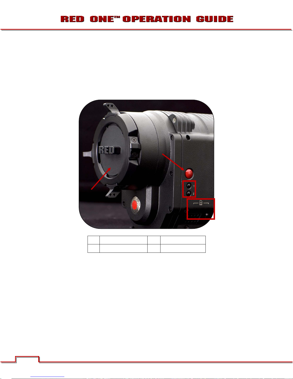
Left Front of Camera ........................................ 6
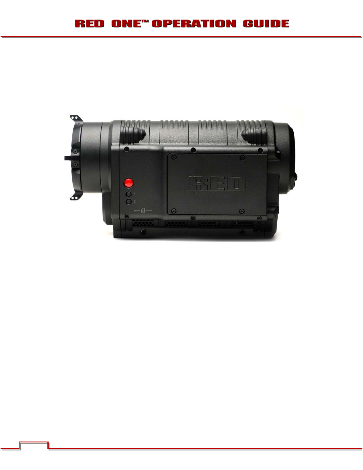
Rear of Camera ................................................ 7
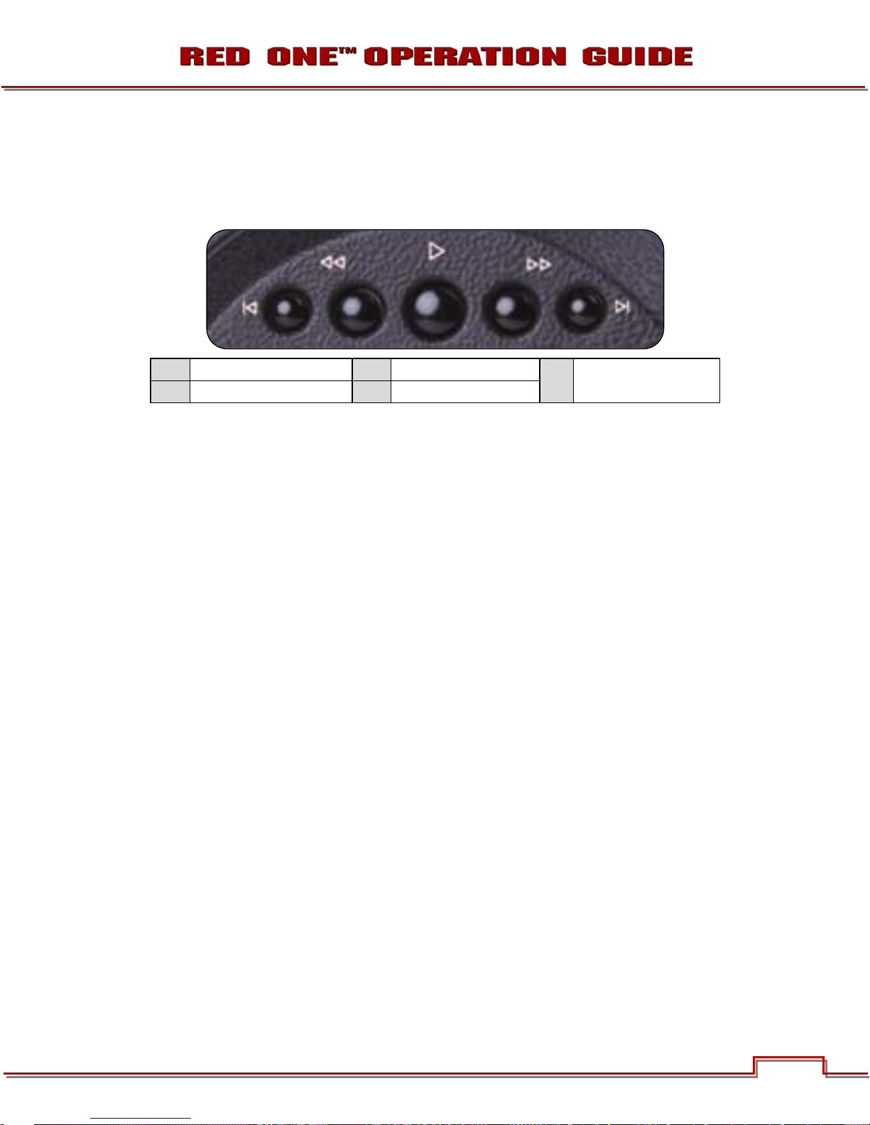
UNDO/EXIT Buttons......................................... 9
Joystick Operation ........................................... 9
Power On/Off switch...................................... 10
Camera Connectors............................................ 11
Right Side of Camera..................................... 11
Rear of Camera .............................................. 12
Camera Displays................................................. 13
Camera LCD Status Display........................... 13
RED LCD Display ........................................... 14
RED EVF Display............................................ 14
External HD-SDI or HDMI Monitors ............... 15
THEORY OF OPERATION...................................... 16
MYSTERIUM® Sensor........................................ 16
Image Processing ............................................... 16
Audio Recording................................................. 17
Line Level Inputs................................................. 17
Microphone Level Inputs .................................... 17
Video Monitoring Outputs................................... 17
RED LCD and RED EVF...................................... 18
Record Indicator ................................................. 20
Recording Errors ............................................ 20
Digital Magazines ............................................... 21
Metadata ........................................................ 21
Clip Naming Conventions .............................. 21
SMPTE Timecode .......................................... 22
Power Consumption ........................................... 22
BASIC OPERATION ............................................... 23
Power Up / Down ............................................... 23
Operating Camera using RED Charger............... 24
Recharging Batteries using RED
Charger............................................................... 24
First Time Use - Setting Up Your RED
ONE™................................................................. 25
Connecting Media .............................................. 26
Project Setup...................................................... 26
Resolution ...................................................... 27
Time Base (Formerly Frame Rate).................. 27
Quality ............................................................ 28
Recording ........................................................... 28
Playback ............................................................. 29
Back Focus Adjustment...................................... 29
SENSOR MENU CONTROLS................................. 31
Sensitivity ........................................................... 31
Color Temp......................................................... 31
Shutter Menu ...................................................... 32
Genlock.......................................................... 32
Speed............................................................. 33
Syncro............................................................ 34
Phase ............................................................. 34
Varispeed............................................................ 35
Varispeed ....................................................... 36
Ramp.............................................................. 36
Frame rate...................................................... 37
Time ............................................................... 38
End Rate ........................................................ 38
Time-lapse.......................................................... 38
Enable ............................................................ 38
Speed............................................................. 39
Interval ........................................................... 39
Burst Type...................................................... 39
AUDIO / VIDEO MENU CONTROLS...................... 41
View .................................................................... 41
Video................................................................... 41
Look ............................................................... 41
Color .............................................................. 42
Gain................................................................ 43
Tone ............................................................... 44
Viewfinder Menu ................................................. 45
Color .............................................................. 45
Meter.............................................................. 46
Assists............................................................ 49
Zebras ............................................................ 50
Dark Detail...................................................... 52
Open Gate...................................................... 52
Audio .................................................................. 52
Line Level Inputs ............................................ 53
Microphone Level Inputs................................ 53
Headphone ......................................................... 53
SYSTEM MENU CONTROLS................................. 55
Sound Menu ....................................................... 55
REC Enable .................................................... 55
Output Level................................................... 55
48V Enable..................................................... 56
Media Menu........................................................ 56
Pre-Record..................................................... 56
Unmount ........................................................ 58
Format............................................................ 58
Change........................................................... 58
Reset.............................................................. 59
Project Menu ...................................................... 59
Slate............................................................... 59
Configure ....................................................... 60
Timecode ....................................................... 62
QT Proxies ..................................................... 65
Monitor ............................................................... 65
Frame Guide .................................................. 66
Preview .......................................................... 70
Test Signal ..................................................... 70
HD-SDI........................................................... 72

Build 20 v20.1.6
©2009 RED.COM INC. OCTOBER 19, 2009
22
EVF Refresh ................................................... 72
Setup .................................................................. 73
Preferences .................................................... 73
Maintenance................................................... 80
Setting System Clock..................................... 86
Write Log........................................................ 88
Remote........................................................... 88
S4/i................................................................. 89
APPENDIX A: UPGRADING CAMERA
FIRMWARE............................................................. 90
Verify Current Camera Firmware ........................ 91
Upgrade Procedure ............................................ 91
APPENDIX B: MANAGING DIGITAL
MEDIA..................................................................... 94
Formatting Media ............................................... 94
Re-formatting Media........................................... 96
Media Capacity Remaining Status ..................... 98
Remove Media from Camera
(Unmount) ........................................................... 98
Copying Media ................................................... 99
Erasing Media Using Macintosh OS X.............. 100
Erasing Media Using Windows ......................... 100
Media Errors ..................................................... 101
SD Memory Card / USB Memory
Devices ............................................................. 102
SD Memory Card ......................................... 102
USB Memory Device.................................... 102
APPENDIX C: SAVING LOOK/USER
PROFILE ............................................................... 103
Look.................................................................. 103
Export Look.................................................. 103
Import Look.................................................. 104
User Profile ....................................................... 104
Export User Profile....................................... 104
Import User Profile ....................................... 105
Data Not Saved During Export ......................... 105
APPENDIX D: INPUT/OUTPUT
CONNECTORS ..................................................... 106
Right Side of Camera ....................................... 106
Time Code Input / Output ............................ 106
Out ............................................................... 107
Aux / RS232 Port ......................................... 107
Viewfinder (RED EVF) Interface .................... 108
Monitor (RED LCD) Interface........................ 108
Line Level / Microphone Level Audio
Inputs ........................................................... 108
Line Audio Output ........................................ 110
Headphone Audio Output ............................ 111
USB-2 Master .............................................. 111
USB-2 Slave................................................. 112
Genlock Input............................................... 112
Program (Dual-link) HD-SDI ......................... 113
Preview HD-SDI ........................................... 114
HDMI ............................................................ 114
Rear of Camera ................................................ 115
DC Power Input............................................ 116
Drive Interface .............................................. 116
Auxiliary Power Outputs............................... 117
APPENDIX E: POST PRODUCTION.................... 118
Software Tools.................................................. 118
RED™ QuickTime Codec............................. 119
RED Alert! ®................................................. 119
REDCINE®................................................... 122
APPENDIX F: POSSIBLE ERRORS,
ISSUES AND SOLUTIONS................................... 123
APPENDIX G: MENU MAPS ................................ 124
Sensor Menu Map ............................................ 124
Video Menu Map .............................................. 125
System Menu Map............................................ 126
1 of 3 ............................................................ 126
2 of 3 ............................................................ 127
3 of 3 ............................................................ 128
RED ONETM Operation Guide
Camera Build 20 Version 20.1.6
October 19, 2009

Build 20 v20.1.6
OCTOBER 19, 2009 ©2009 RED.COM INC.
3
OPERATION GUIDE REVISIONS
The following changes have been made since the previous revision of this Operation Guide:
•Under AUDIO/VIDEO MENU CONTROLS > VIEWFINDER MENU > METER, the information has been
revised.
•Under SYSTEM MENU CONTROLS > SETUP > MAINTENACE > BLACK SHADING, BLACK SHADING
ERRORS section has been added.
•VERIFY CURRENT CAMERA FIRMWARE has been added to APPENDIX A: UPGRADING CAMERA
FIRMWARE.
•APPENDIX G: MENU MAPS has been added.
DISCLAIMER
RED™ has made every effort to provide clear and accurate information in this Operation Guide, which is
provided solely for the user’s information. While thought to be accurate, the information in this document
is provided strictly “as is” and RED™ will not be held responsible for issues arising from typographical er-
rors or user’s interpretation of the language used herein that is different from that intended by RED™. All
safety and general information is subject to change as a result of changes in local, federal or other appli-
cable laws.
RED™ reserves the right to revise this Operation Guide and make changes from time to time in the con-
tent hereof without obligation to notify any person of such revisions or changes. In no event shall RED™,
its employees or authorized agents be liable to you for any damages or losses, direct or indirect, arising
from the use of any technical or operational information contained in this document.
COPYRIGHT
Copyright ©2009 RED.COM, INC.
All rights reserved. No part of this document may be reproduced, transmitted, transcribed, or translated
into any language in any form without the prior written consent of RED™.
TRADEMARKS
RED ONE™, MYSTERIUM®, RED™, RED DIGITAL CINEMA™, REDCINE®, RED BRICK®, REDFLASH™,
RED-RAM®, RED-DRIVE®, REDSPACE™, RED Alert! ®, R3D™, and REDCODE™ are trademarks of
RED.COM, INC.

Build 20 v20.1.6
©2009 RED.COM INC. OCTOBER 19, 2009
44
BEFORE YOU START
Congratulations on your purchase of a RED ONE™ camera. Please read the attached safety instructions,
then carefully unpack the camera body any accessories. If there is any physical damage or missing com-
ponents for your camera body and any accessories, please file a support ticket at
www.RED.com/support.
RED ONE™ Camera
IMPORTANT INFORMATION
- READ BEFORE USING YOUR CAMERA -
GENERAL USE
DO NOT MODIFY OR DISMANTLE: Do not attempt to open your camera, lens or other accessory as
doing so may expose you to electric shock and serious injury. There are no user-serviceable parts inside.
Alteration or repairs made to the camera, lens or other accessory, except by a RED™ authorized service
facility, will void the Limited Warranty. Users are not permitted to make design changes or otherwise mod-
ify the operation of the camera, lenses or other accessories, without the express written approval of RED
DIGITAL CINEMA™.
STORAGE: Store in a protected, level and ventilated place. Avoid exposure to temperature extremes,
damp, severe vibration, strong magnetic fields, direct sunlight or local heat sources during storage. Re-
move any batteries from the camera before storage.
Note that storing batteries fully charged or in high temperature conditions may permanently reduce the life
of the battery. Available battery capacity may also be temporarily lessened after storage in low tempera-
ture conditions.

Build 20 v20.1.6
OCTOBER 19, 2009 ©2009 RED.COM INC.
5
The recommended storage and usage temperatures for your camera, lenses and other accessories are:
- Operating range: 0°C to +40°C (32°F to 104°F)
- Storage range: -20°C to +50°C (-4°F to 122°F)
If there are any performance issues with your camera or accessories within this operating range, please
file a support ticket on www.RED.com/support.
MOISTURE: Avoid exposing your camera to moisture. The unit is not waterproof, so contact with water
could cause permanent damage to the unit as well as electric shock and serious injury to the user. Do not
use the camera in the rain or under other conditions with high moisture and immediately remove the pow-
er source if exposed to moisture.
AVOID SHOCK: Do not expose your camera to excessive vibration or impact. Be careful not to drop your
camera. Internal mechanisms may be damaged by severe shock. Mechanical alignment of optical ele-
ments may be affected by excessive vibration.
CLEANING: When cleaning your camera, remember that it is not waterproof and moisture can damage
electronic circuitry. Do not rinse or immerse any element of the camera, lens or other accessory, keep
them dry at all times. Do not use soaps, detergents, ammonia, alkaline cleaners, and abrasive cleaning
compounds or solvents. These substances may damage lens coatings and electronic circuitry.
LASER BEAMS: Avoid imaging of laser beams as they may cause damage to the sensor.
BATTERY: Lithium Ion batteries may be subject to special handling requirements pursuant to federal and
local laws. Please refer to specific shipping instructions included with your battery regarding proper trans-
port of your battery. Do not handle your battery if it is damaged or leaking. Disposal of batteries must be in
accordance with local environmental regulations. For example, California law requires that all rechargeable
batteries must be recycled by an authorized recycle center.
ELECTROMAGNETIC INTERFERENCE: The use of devices using radio or other communication waves
may result in the malfunction or interference with the unit and/or with audio and video signals.
FCC RULES: This equipment has been tested and found to comply with the limits for a Class A digital de-
vice pursuant to Part 15 of the FCC Rules. These limits are designed to proved reasonable protection
against harmful interference when the equipment is operated in a commercial environment.
This equipment generates, uses, and can radiate radio frequency energy and, if not installed and used in
accordance with the instructions, may cause harmful interference to radio communications. Operation of
this equipment in a residential area is likely to cause interference, in which case, the user will be responsi-
ble for correcting the interference at the user’s own expense.

Build 20 v20.1.6
©2009 RED.COM INC. OCTOBER 19, 2009
66
CAMERA CONTROLS, CONNECTORS AND DISPLAYS
This section describes the physical controls, connectors and displays on the RED ONE™ camera body.
CAMERA CONTROLS
LEFT FRONT OF CAMERA
This section describes the physical controls on the RED ONE™ camera body.
A PL Lens Mount Cover B Record Button
C User Keys 1 and 2 D SD Memory Card
Figure 1 – Left Front Camera Controls
A PL Lens mount is provided as standard with the RED ONE™ camera. The mount is compatible with the
majority of S35mm, 35mm and S16mm cinematography lenses. In addition, broadcast B4 mount lenses
may be used if the camera is equipped with the optional B4 to PL mount optical converter.
The PL Lens mount (A) includes a 4-pin S4/i data interface. This allows the camera to gather lens metada-
ta from lenses supplied by RED™ and Cooke Optics. Ltd, using S4/i protocol.
On the left side of the camera body is a RECORD key (B) and two User Keys (C). User Key 1 is pre-
assigned to AUTO WB and User Key 2 is pre-assigned to 1:1 FOCUS CHECK. Focus check zooms in the
image to allow for precise focus adjustment. These assignments can be changed in the KEYMAP prefe-
rences menu. Refer to KEY-MAP under PREFERENCES in SET UP under SYSTEM MENU CONTROLS.
NOTE: If User Key 2 assignment is changed, FOCUS CHECK is still available through the EVF but-
tons. Refer to RED™ EVF DISPLAY under CAMERA DISPLAYS for additional information.
A
B
C
D

Build 20 v20.1.6
OCTOBER 19, 2009 ©2009 RED.COM INC.
7
An SD Memory Card slot (D) is located below User Key 2, which supports most SD Cards of up to 1GB
capacity. It is not possible to store video or audio data to the card SD card, however it may be used for
camera firmware upgrades and to store USER PROFILE and LOOK files.
REAR OF CAMERA
A Clip Start / Previous Clip C Clip Play / Pause E Clip End / Next Clip
B Play Reverse D Fast Forward
Figure 2 – Rear Upper Playback Camera Controls
A. Cues the Clip to its Start Frame. If already at the Start Frame, pushing this key again will cue to the
Start Frame of the previous clip recorded on the digital media, if one exists.
B. FRW – Plays the clip back in reverse. Each push of this key cycles clip playback between – 1 x, - 2 x
and - 8 x speed playback.
C. PLAY/PAUSE - Used to enter PLAYBACK mode and to initiate playback of the last recorded clip. Push
once to enter Playback mode, a second time to start playback. Once in clip playback, this key acts as
a Play/Pause toggle.
D. FFW - Plays the clip at higher speeds. Each push of this key cycles clip playback between 1 x, 2 x, 8 x
and 32 x speed playback.
E. Cues the Clip to its End Frame. If already at the End Frame, pushing this key again will cue to the Start
Frame of the next clip recorded on the digital media, if one exists.
NOTE: It is not necessary to exit Playback mode prior to the next recording. To exit playback mode,
either push the RECORD key, or push the EXIT key to the left of the joystick.
When in playback, all cursors will be disabled, and the camera provides a clean feed of the recorded vid-
eo signal at 1280 x 720 resolution on the Preview HD-SDI and HDMI outputs.
Depending on the capture frame rate, pull down will be added to create a standard 1280 x 720 progres-
sive scan 59.94Hz or 50.00 Hz high definition video signal. SMPTE timecode is embedded on the Preview
HD-SDI output, and both Preview HD-SDI and HDMI outputs provide up to 4 independent channels of 24-
bit 48KHz audio.
NOTE: If PLAYBACK MODE preference is set to 1080p, HD Preview HD-SDI and HDMI outputs will
switch to 1920 x 1080p progressive scan 10-bit 4:2:2 at 23.98, 24.00, 25.00 or 29.97 fps.
NOTE: If PLAYBACK LOOK preference is set to CLIP, the color adjust metadata will be read from
the recorded clip. If set to CAMERA, the metadata used are the current camera settings.
A B C D
E

Build 20 v20.1.6
©2009 RED.COM INC. OCTOBER 19, 2009
88
A User Menus Select F UNDO / Alternate Action
B Sensor Menu G System Menu
C Audio / Video Menu H Record Start / Stop
D EXIT Menu I Record/Ready (OK) LED
E Joystick J LCD Display
Figure 3 – Rear Center Camera Controls
On the rear of the camera, several buttons surround a daylight readable LCD status display (J).
To the left of the status display are three User Menu buttons (A), which by default provide direct access to
SENSITIVITY (A), SHUTTER (B) and COLOR TEMPERATURE (C) menus. The specific function of these
keys may be re-programmed by the user, to provide quick access to other functions. Refer to KEY-MAP
under PREFERENCES in SET UP under SYSTEM MENU CONTROLS.
NOTE: For quick programming of the keys, navigate to the desired menu you wish to program the
A, B or C key to, then push and hold the desired key until external monitors display “User button
A/B/C has been assigned to this menu. The selected key will now be programmed to the new menu
destination. To reset keys to default settings, go to RESTORE. A reboot of the camera may be ne-
cessary to restore defaults.
Below the LCD status display are the Joystick (E), Exit (D), Undo / Alternate Action (F) and RECORD (H)
buttons, plus the SENSOR (B), AUDIO / VIDEO (C) and SYSTEM (G) menu buttons. The camera control
menus are logically grouped under these last three buttons to provide streamlined camera operations.
The status display reports key camera status values, and is complimented by two LED’s (I): the REC LED
provides record status (illuminates Red when recording), while the OK LED indicates the camera is ready
for operation (illuminates Green when ready).
A
B
C
D E F
G
H
I
J

Build 20 v20.1.6
OCTOBER 19, 2009 ©2009 RED.COM INC.
9
UNDO/EXIT BUTTONS
- EXIT will exit the menus.
- Press and hold UNDO and SYSTEM menu buttons at the same time to navigate to the last displayed
menu before exiting.
- Press and hold UNDO and EXIT buttons at the same time to unmount media from the camera. Refer
to REMOVE MEDIA FROM CAMERA (UNMOUNT) under APPENDIX B: MANAGING DIGITAL MEDIA.
- Press and hold UNDO and push the JOYSTICK to display the current camera firmware version.
JOYSTICK OPERATION
- Left/Right to navigate menu selections.
- Up to go previous screen (will exit menu when at top level).
- Down to go to next menu (similar to Push to select a menu item).
- Rotate (turn/twist like a knob) changes value in highlighted box.
- Push (like a button) to enter a selection.

Build 20 v20.1.6
©2009 RED.COM INC. OCTOBER 19, 2009
1010
POWER ON/OFF SWITCH
Power on/off switch (A) is located on the lower rear of the camera. Press once to power up/power down
the camera.
A Power ON / Off Switch
Figure 4 – Rear Lower Camera Controls
A

Build 20 v20.1.6
OCTOBER 19, 2009 ©2009 RED.COM INC.
11
CAMERA CONNECTORS
RIGHT SIDE OF CAMERA
This section describes the physical connectors on the RED ONE™ camera body. For detailed description
and operation refer to APPENDIX D: INPUT/OUTPUT CONNECTORS.
A Headphone H USB Slave
B Program HD-SDI (A) I Audio Out
C Program HD-SDI (B) J Timecode
D Preview HD-SDI K
Audio In Ch 1 – 4 (1-2 Upper
Left - Right, 3-4 Lower Left -
Right)
E Video Genlock L Viewfinder for RED™ EVF
F HDMI Out M Monitor for RED™ LCD
G USB Master N Aux / RS232
Figure 5 – Right Side Camera Connections
The right side of the camera contains all the video, audio and time code inputs and outputs.
From top left to bottom right, these comprise a 3.5mm stereo headphone jack (A), and four DIN 1.0/2.3
video connectors that support Program HD-SDI (B, C), Preview HD-SDI (D) and Video Genlock (E).
Next is an HDMI output (F), a USB-2 “master” port (G) to connect the camera to another camera or to
connect a USB memory device to update camera firmware, a USB-2 “slave” port (H) to connect the cam-
era to another camera or computer based controller, a 5-pin mini-XLR audio output (I), a 5-pin timecode
input/output (J) and four (4) 3-pin mini-XLR audio inputs (K). Finally there are two 16-pin push lock LEMO
connectors (L, M) that provide video, communications and power for a RED™ EVF (L) and RED™ LCD
(M), and a 10-pin push lock LEMO connector (N) supporting the Aux/RS232 port that can interface to a
variety of B4 lenses and lens motor control devices.
One 6-inch length DIN 1.0 / 2.3 to BNC video adaptor cable and one 9-inch length 3-pin mini-XLR to mini-
XLR cable plus a mini-XLR to full size XLR adaptor are provided with the camera.
Additional video and audio adaptor cables may be ordered online at www.RED.com/store.
A
B C
D E
F
G
H
I
J
K
L
M
N

Build 20 v20.1.6
©2009 RED.COM INC. OCTOBER 19, 2009
1212
NOTE: Cameras shipped prior to Sept 15th 2008, may have an earlier revision of the audio board
and no S4/i pins installed in the P/L mount. Contact RED™ customer service about appropriate au-
dio cables to use with these systems, and hardware upgrade options.
REAR OF CAMERA
A Aux Power / GPIO A C Camera Power 11.5 – 17V DC Input
B Aux Power / GPIO B D e-SATA Interface (to RED-DRIVE or
RED-RAM digital magazine)
Figure 6 – Lower Rear Camera Connectors
On the rear of the camera are the two 4-pin Auxiliary Power / GPIO outputs (A, B), 6-pin camera system
POWER input (C) and a 16-pin DRIVE interface (E).
Each Auxiliary Power / GPIO connector can supply 1.75 amps of unregulated 11.5 – 17V DC to accesso-
ries such as range finders or low power lens motors. The upper connector provides a GPI trigger (user
programmable but defaulted to Record Start / Stop) and a Record Tally output. The lower connector pro-
vides a GPI trigger (user programmable but defaulted to Record Start / Stop – for Time-lapse set to TIM-
LAPSE in GPIO preferences) and a Frame Recorded Tally output.
The DRIVE interface supplies power and data over e-SATA protocols to record REDCODE™ (TM) RAW
compressed video data, metadata and audio to RED-DRIVE® or RED-RAM® digital media.
A
B C
D

Build 20 v20.1.6
OCTOBER 19, 2009 ©2009 RED.COM INC.
13
CAMERA DISPLAYS
The LCD status display mounted at the rear of the RED ONE™ camera provides a snapshot of the camera
setup.
RED™ LCD and RED™ EVF monitors are factory preset digital displays. There are no saturation, peaking
or contrast adjustments as found on analog monitors to correct color reproduction.
Monitor outputs on the RED ONE™ camera are set up for REC 709 gamma and color space.
Image intensity can be adjusted to compensate for ambient lighting conditions. For the RED™ LCD, use
the Up / Down keys on top of the display. For the RED™ EVF use the rotary encoder.
To assist with exposure, all monitor outputs can display a dual Zebra pattern and a False Color exposure
meter overlaid on the video. In addition the RED™ EVF and RED™ LCD outputs can display a RGB histo-
gram, exposure “stop lights” and RAW sensor data exposure meter.
CAMERA LCD STATUS DISPLAY
Figure 7 – Camera LCD Display
The LCD status display elements include:
•Timecode / Status: Displays current timecode
value, clip name or system messages
•ASA Value: Displays current exposure index
•Project Frame Rate: Displays the project frame
rate, 23.98 fps in this example
•Timecode: Displays timecode lock status
•White Balance: Displays current color temp
•Media: Displays remaining media capacity in %
•Power: Displays remaining battery capacity in
% (as shown) or connection to DC power
•Shutter Speed: Displays current exposure time
•Format: Displays video recording format, 4K
RAW in this example
NOTE: The timecode value reported is Edge Code or Time Code, as selected by the user in the
TIMECODE menu. During recording, the Clip Name is reported in this display field.
TIMECODE / STATUS
ASA VALUE
WHITE BALANCE
SHUTTER SPEED
TIMECODE
FORMAT
PROJECT FRAME RATE
MEDIA POWER

Build 20 v20.1.6
©2009 RED.COM INC. OCTOBER 19, 2009
1414
RED LCD DISPLAY
Figure 8 –RED™ LCD
Two (2) round and two (2) triangular buttons are located on top of the RED™ LCD.
•The two triangular buttons (A) in the center are used to increase or decrease backlight intensity.
•Right button (B) switches display between Video plus Frame Guides and Menus, to Video plus Frame
Guides only.
•Left button (C) is User Key 5 and can be programmed. Refer to KEY-MAP under PREFERENCES in
SET UP under SYSTEM MENU CONTROLS.
RED EVF DISPLAY
Figure 9– RED™ EVF
The RED™ EVF comprises the following components:
A. High-resolution color display: Provides a 1280 pixel x 848-pixel resolution progressive scan color im-
age equivalent to viewing a 17” reference color monitor from a distance of approximately 4 ft.
D
C
B
A
B
A
E
C

Build 20 v20.1.6
OCTOBER 19, 2009 ©2009 RED.COM INC.
15
B. Focus ring: May be adjusted for optimal subject focus for your eye. Available diopter range is +1.5 to -
2.0.
C. Rotary encoder/switch: Used to adjust a variety of parameters. These include the EVF Intensity, but
also camera parameters such as Ch1 Audio Level or Ch 2 Audio Level, and Shutter speed, Varispeed
frame rate and ISO setting. For detailed information on enabling and using this feature, go to EVF
MENU under DISPLAY in PREFERENCES under SETUP in SYSTEM MENU CONTROLS.
D. Two (2) programmable USER KEY 3 and 4 buttons.
•Default setting of USER KEY 3 turns COLOR TOOLS (monochrome or false color) On/Off.
•Default setting of USER KEY 4 turns the METER (e.g. WAVEFORM or FOCUS ASSIST) On/Off.
•USER KEY 3 and 4 can be programmed. Refer to KEY-MAP under PREFERENCES in SET UP un-
der SYSTEM MENU CONTROLS.
E. One (1) fixed function button.
•The fixed function button (located closest to the focus ring) selects 1:1 FOCUS CHECK mode.
When selected this shows the central region of the MYSTERIUM® sensor in native 4K resolution.
NOTE: This function is not available during RECORD.
EXTERNAL HD-SDI OR HDMI MONITORS
External monitors can be connected to the camera through the HDMI and HD-SDI (2) ports located on the
side of the camera. Refer to CAMERA CONNECTORS.
To aid external monitor alignment, the RED ONE™ camera provides a range of test signals including
SMPTE Bars, Back and White Fields, Luma and Chroma Ramps, and a Chip Chart. Refer to TEST SIG-
NAL under MONITOR in SYSTEM MENU CONTROLS.
NOTE: The internal test signals cannot be recorded; they are provided to align external video re-
corders or monitors connected to the camera via the HD-SDI or HDMI ports.
TROUBLESHOOTING EXTERNAL MONITORS
If after connecting the camera to an external monitor and the camera display is not shown completely on
the monitor display, press SYSTEM menu button, select MONITOR and try the following:
•Select PREVIEW and change setting between MENUS [DVI] or VIDEO [720p].
•Select HD-SDI and change setting between 50.00 HZ or 59.94 HZ.

Build 20 v20.1.6
©2009 RED.COM INC. OCTOBER 19, 2009
1616
THEORY OF OPERATION
The RED ONE™ Digital Cinema camera provides high performance digital imaging over a wide range of
frame rates and optical formats including Super 35mm, 35mm and Super16mm. The camera is supplied
as standard with a PL mount, and may be configured with 19 mm rods to accommodate most cinemato-
graphy lenses, matte boxes and follow focus systems. Adaptors for 15mm offset studio and 15mm
lightweight rods are also available.
In addition to compatibility with existing PL mount cinematography lenses; a select range of S35/35mm
format PL mount prime and zoom lenses are available from RED DIGITAL CINEMA™.
Other lens mounts, including Canon FD, and Nikon F are available from RED™ and 3rd parties, permitting
the use of Nikkor and Canon photographic lenses. To use these mounts the PL mount must be removed.
It is recommended that this should be done only in a dust-free environment, as the sensor and optical
path will be exposed to the elements during this process.
A B4 mount to PL mount adaptor is also available to permit use of 2/3” HD lenses on the RED ONE™
camera. The optical coverage it provides is equivalent to S16 mm. Hence, the maximum recording resolu-
tion with these lenses will be 2K RAW. (2048 x 1152 pixel progressive scan)
MYSTERIUM® SENSOR
The MYSTERIUM® sensor has been specifically designed for use with the RED ONE™ camera, and pro-
vides variable frame rate imaging over 1- 30fps in 4K, 1-60fps in 3K resolution, and 1-120fps in 2K resolu-
tion record modes.
Native color balance for the MYSTERIUM® sensor is 5,000 degrees Kelvin, but may be electronically
compensated for any color temperature in the range 1,700 to 10,000 Kelvin. White Balance presets are
available for Tungsten (3200K) and Daylight (5600K) lighting; the camera may also calculate a color neu-
tralizing White Balance value using a standard white card technique.
MYSTERIUM® includes integrated 12-bit resolution analog to digital conversion, capable of delivering up
to 11 stops of dynamic range when operating in daylight at a sensitivity of 320 ISO.
IMAGE PROCESSING
Images received from the MYSTERIUM® sensor are formatted as pixel defect corrected (but not color
processed) 12-bit RAW data - similar in image quality to a high end digital stills camera.
The sequence of 12-bit RAW images received from the sensor is compressed using proprietary wavelet
based REDCODE™ RAW compression. The RAW data recorded is independent of the RGB signal moni-
tored from the monitoring path. ISO, white balance or other RGB color space adjustments made to the
monitoring path are not burned into the recorded 12-bit RAW data.
Images can be stored on a high-speed Compact Flash, RED-DRIVE® or RED-RAM® media.
The camera’s monitoring path converts 12-bit RAW sensor data white balanced 10-bit 1280 x 720 pixel
RGB 4:4:4 video. This signal may be modified using ISO, white balance or other RGB color space adjust-
ments and provides monitor feeds for the RED™ EVF, RED™ LCD, Preview HD-SDI and HDMI outputs.

Build 20 v20.1.6
OCTOBER 19, 2009 ©2009 RED.COM INC.
17
AUDIO RECORDING
The RED ONE™ includes four channels of analog audio input processing, Peak Level meter, headphone
monitor and 2-channel balanced analog audio output. Audio is digitized at 24-bit depth and 48KHz and
recorded in synchronization with video and timecode to the attached media. Digital audio is also embed-
ded in the HDMI, Preview and Program HD-SDI outputs.
Line Level and Microphone Level analog audio input signals are routed via a high quality A/D and pre-
amplifier, whose gain stage may be controlled using the Input Level control to achieve the desired audio
reference / recording level.
To assist with audio operating reference level setup, the camera provides a color-coded 3dB per division
Peak Level meter with 0dBu (-2odBFS) Witness Mark in the Graphical User Interface.
Peak Level meter range is –34dBu to +20dBu (-54dBFS to 0dBFS) and provides clip indication.
LINE LEVEL INPUTS
Line level audio inputs are designed to operate at unity gain (0dB Input Level); therefore an appropriate
line output level should be established by your field production mixer or other external signal source.
Reference signal level for Line inputs is 0dBu / 0.775 volts RMS / -20dBFS when operating at 0dB Input
Level. The maximum input signal that can be applied before the onset of input signal clipping is +18dBu /
6.5 volts RMS / - 2dBFS. I.e. this setting supports a guaranteed minimum of 18dB of input signal head-
room above reference, plus the maximum available Signal to Noise Ratio for the resulting 24-bit digital
recording.
MICROPHONE LEVEL INPUTS
The recorded signal levels of Microphone inputs are affected by the sensitivity of the microphone and the
Input Level setting. Range is +26dB to +54dB, with a default value of +26dB. The camera operator
should choose an Input Level that aligns the input signal to the reference line drawn vertically through the
camera’s PPM, indicating 0dBu.
This setting supports a guaranteed minimum of 18dB of input signal headroom above reference, plus the
maximum available Signal to Noise Ratio for the resulting 24-bit digital recording.
VIDEO MONITORING OUTPUTS
In its default configuration, the RED ONE™ camera can simultaneously support a RED™ EVF, RED™
LCD, 3 HD-SDI outputs and one HDMI output, with two of these outputs supporting full GUI overlay
graphics.
Default setting for GUI support is RED™ EVF and RED™ LCD. However, if either one of these is not
present, full GUI overlay support is automatically enabled on HD-SDI and HDMI outputs.
RED™ EVF: 1280 x 848 resolution RGB 4:4:4 progressive video display with Surround View, frame guides
and safe action / title overlays, zebra and false color exposure overlays, waveforms, camera status and
operation menus.
RED™ LCD: 1024 x 600 resolution RGB 4:4:4 progressive video display with Surround View, frame
guides and safe action / title overlays, zebra and false color exposure overlays, waveforms, camera status
and operation menus.

Build 20 v20.1.6
©2009 RED.COM INC. OCTOBER 19, 2009
1818
PROGRAM HD-SDI: When in record mode, these connectors provide two extra copies of the HD-SDI
PREVIEW signal. When in playback mode, these connectors provide a dual-link 10-bit RGB 4:4:4 video
signals.
PREVIEW HD-SDI: 1280 x 720 resolution 10-bit 4:2:2 video output (720p 50.00 /59.94 Hz).
PREVIEW HDMI: 1280 x 720 resolution 10-bit 4:2:2 video output (720p 50.00 /59.94 Hz).
NOTE: If a RED™ EVF or RED™ LCD is connected, the PREVIEW HD-SDI and HDMI outputs will
provide Surround View, frame guides, safe action / title, and timecode / clip name. If both RED™
EVF and RED™ LCD are connected, these outputs only support Surround View.
NOTE: Only if a RED™ EVF or RED™ LCD is connected, the HDMI output can also support a 1280 x
848 resolution video output with Surround View, frame guides, safe action / title, timecode / clip
name, waveform, and camera status and operation menu overlays. This signal should be compati-
ble with the majority of DVI based SXGA+ computer monitors.
To select between these modes perform the following:
1. Push the SYSTEM menu button.
2. Using joystick, select MONITOR. Push the joystick in or down to select.
3. Using the joystick, select PREVIEW.
4. Twist joystick to select MENUS (DVI) or VIDEO (720p) in the PVW OUTPUT box above the EVF RE-
FRESH box - default is VIDEO (720p).
5. To set selection and exit the menu, push the EXIT button or move the joystick up two times (x2).
The Preview Output setting will be held in camera memory. Once it is set it will not need to be re-set when
power cycling the camera.
RED LCD AND RED EVF
The optional RED™ LCD and RED™ EVF are specialized video monitors, that may be attached to the
camera body, and provide a variety of user tools to assist framing, focus and exposure.
Surround View, which is an additional visible area outside the actual recorded image.
Frame guidelines show common film presentation and television formats such as 2.40:1 and 1.85:1, pic-
ture center, and/or television aspect ratios such as 16:9, 14:9 and 4:3.
Focus is aided by the high resolution of the displays, 1:1 Focus Check function, and two user selectable
waveform based focus assist meters.
Exposure is aided by dual zebras a false color meter and Luma and RGB histograms.
Other manuals for ONE
3
Table of contents
Other RED Camcorder manuals
Popular Camcorder manuals by other brands

Panasonic
Panasonic HDC-Z10000 Basic operating instructions

Sony
Sony Handycam Vision CCD-TRV95 operating instructions

Samsung
Samsung VP-L700 Owner's instruction

Sony
Sony Handycam DCR-PC100 operating instructions

Panasonic
Panasonic NV-GS400 operating instructions

Hitachi
Hitachi DZ-MV580E instruction manual