Redback A 4931 User manual

www.redbackaudio.com.au Redback® Proudly Made In Australia 1
Redback® A 4411 4 Channel Stereo Mixer
Operating Manual
A 4411 4 CHANNEL STEREO MIXER
Optional Accessories
A 4931 Local Input Remote Wall Plate (U/UTP Cat5)
A 4931V Local Input Remote Wall Plate (U/UTP Cat5)
A 4932 Local Input Box (U/UTP Cat5)
IMPORTANT NOTE:
Please read these instructions carefully from front to back prior to installation.
They include important setup instructions.
Failure to follow these instructions may prevent the unit from working as designed.
Distributed by Altronic Distributors Pty. Ltd.
Phone: 1300 780 999 Fax: 1300 790 999 Internet: www.altronics.com.au
User manual revision number: 1.2 23/09/2020
A 4931 Local Input Plate A 4932 Local Input Box
A 4931V Local Input Plate

www.redbackaudio.com.auRedback® Proudly Made In Australia2
Redback® A 4411 4 Channel Stereo Mixer
REDBACK is a registered trademark of Altronic Distributors Pty Ltd
Since 1976 Redback ampliers have been manufactured in Perth, Western Australia by Altronics. With close to 40 years
experience in the commercial audio industry, we offer consultants, installers and end users reliable products of high build
quality with local product support. We believe there is signicant added value for customers when purchasing an
Australian made Redback amplier or PA product
Australian Made Status
All Redback house products made by Altronics will now be sporting the ofcial Australian Made logo. Since starting
manufacturing of commercial audio equipment in the mid 70’s we have always taken pride in producing a quality local
product.
The new adoption of the Australian Made logo will help us get the word out to local and export markets that our
products carry the ofcial compliance seal of the Australian Made campaign. We have always pushed our ‘local is better’
line in all of our marketing efforts, it’s always an added boost when you are backed up by a widely recognised and
respected icon.
Industry leading 10 year warranty.
There’s a reason we have the industry leading DECADE warranty. It’s because of a long tried and tested history of
bulletproof reliability. We’ve heard PA contractors tell us they still see the original Redford amplier still in service in schools
- that’s over 40 years of operation - and still going strong!
Published by Altronic Distributors
© 2020 Altronic Distributors

www.redbackaudio.com.au Redback® Proudly Made In Australia 3
Redback® A 4411 4 Channel Stereo Mixer
1.0 INTRODUCTION
Designed to meet the growing demands of PA systems utilising high power stereo ampliers, it features 2 balanced micro-
phone and 2 auxiliary inputs. Perfect for aerobics use, bars, bistros, sporting clubs.
Two sets of tone controls are provided; one for the microphone inputs and one for the auxiliary inputs.
Master volume is provided on the rear panel.
Inputs: Each microphone input incorporates a 3 pin balanced XLR socket on the rear panel with 15V DC phantom power-
ing. An additional 6.35mm socket is provided on the front panel for input 1. Auxiliary inputs are stereo and use dual RCA
sockets. A 3.5mm stereo jack socket (Music Input) is also provided for auxiliary input 1 on the front panel, suitable for the
output of an MP3 player or similar.
Outputs: RCA sockets are provided for left and right line level and 3 pin XLR sockets for left and right 600Ω balanced
outputs. Variable mute adjustment is provided for the microphones. This enables the microphone inputs to partially or fully
mute the auxiliary inputs as desired.
2.0 FEATURES
• 2 microphone inputs
• Phantom power on MIc inputs (15V DC)
• 2 line inputs
• Separate tone controls for line and microphones
• Stereo outputs
• 1RU 19” rack mount case
• Master volume on rear panel
• Adjustable line muting
• Front panel mount microphone and line input
• Subwoofer output
• LED VU meter
• VOX active indicator
• Signal Present indicator
• 24V DC input
• 24V DC battery back up terminals
• 10 Year Warranty
• Australian designed & assembled
3.0 WHAT’S IN THE BOX
A 4411 Four Channel Stereo Mixer
24V 1A DC Plugpack
Instruction Booklet

www.redbackaudio.com.auRedback® Proudly Made In Australia4
Redback® A 4411 4 Channel Stereo Mixer
4.0 FRONT PANEL GUIDE
Fig 1 shows the layout of the A 4411 front panel.
Fig 1
1 Mic 1 Input
This 6.35mm socket is connected in parallel with the rear MIc 1 input. Either input can be used and both have
15V DC phantom power.
2 Mic 1 volume control
Use this control to adjust the output volume of Mic 1.
3 VOX 1 Sensitivity
This trimpot is used to set the VOX sensitivity of Mic 1.
4 Mute Level
This trimpot it used to adjust the mute level , which enables the microphone inputs to partially or fully mute the
auxiliary inputs (when the VOX circuit is active).
5 Mic 1 volume control
Use this control to adjust the output volume of Mic 2.
6 VOX 2 Sensitivity
This trimpot is used to set the VOX sensitivity of Mic 2.
7 MIcrophones Bass and Treble Controls
Use these to adjust the Bass and TReble of the microphone inputs.
8 Aux 1 volume control
Use this control to adjust the output volume of Aux 1.
9 Aux 2 volume control
Use this control to adjust the output volume of Aux 2.
10 Music input
This input will override AUX Input 2 when connected. Use this for connection of portable music players.
11 Aux Inputs Bass and Treble Controls
Use these to adjust the Bass and Treble of the auxilliary inputs.
12 VOX Active Indicator
This LED indicates when the VOX circuit is active
13 Signal Presence Indicator
This LED indicates when a signal is present at any of the inputs.
14 LED VU Meter
This LED bargraph provides a visual indication of the output signal.
15 On/Fault Indicator
This led indicates when the unit has power if the LED is blue. If the LED is red a fault has occured with the unit.
16 Standby Switch
When the unit is in standby mode this switch will illuminate. Press this button to switch the unit ON. Once the
unit is ON the On indicator will illuminate. Press this switch again to put the unit back in standby mode.
4 Channel Stereo Mixer
A 4411
Mic Input 1 Mic 1 Mic 2 Aux 1 Aux 2Bass Treble
Music Input
On Standby
Power/
Signal
Present
-12dB -9dB -6dB -3dB 0dB
-15dB
-18dB
VOX
Active
Vox 1
Sens. Mute
Level. Vox 2
Sens.
Bass Treble
- +
0
2
46
8
10 0
2
46
8
10 0
2
46
8
10 0
2
46
8
10 - +- + - +
14
13 15 161 2 5 73 4 6 118 9 10 12

www.redbackaudio.com.au Redback® Proudly Made In Australia 5
Redback® A 4411 4 Channel Stereo Mixer
5.0 REAR PANEL CONNECTIONS
Fig 2 shows the layout of the A 4411 rear panel.
Fig 2
1 Microphone Inputs 1 & 2
There are two microphone inputs which all incorporate a 3 pin balanced XLR. Phantom power (15V DC) is
available at each Mic input. Mic 1 is connected in parallel with the front 6.35mm Socket.
2 Mic Gain
These trimpots are used to adjust the microphone gain of the Mic 1 and Mic 2 inputs (including the front Mic 1
socket).
3 RCA Inputs 1 & 2
The Aux inputs are dual RCA connectors which are internally mixed to produce mono input signals. The input
sensitivity of these inputs can be adjusted by DIP 1.
4 Dip Switches DIP1
These are used to set the input sensitivity of Aux 1 and Aux 2 to either 100mV or 1V.
Switch 1 sets Aux 2 input sensitivity: OFF -100mV, ON - 1V.
Switch 4 sets Aux 1 input sensitivity: OFF -100mV, ON - 1V.
Switches 2 & 3 are not used.
5 Master Volume
Use this to adjust the master volume output from the mixer.
6 XLR Outputs
XLR balanced outputs (600Ω ) are provided for the left and right outputs.
7 Aux Out
Dual RCA’s provide a line level output for recording purposes or to pass the output on to another amplier.
8 Sub Out
A single RCA which provides a dedicated sub level output for use with a sub woofer amplier.
9RJ45 Interface
This is for connection of the A 4931 local input wall plate or A 4932 local input box (optional).
10 DIP 2
Switch 1 activates the Microphone VOX circuit. When this DIP switch is set to ON, Mic1 and Mic2 VOX mute all
other inputs.
Swithes 2 - 4 are not used.
11 Micro SD Card
This has been provided in case the mixer requires a rmware update (Note: A Micro SD card is not supplied).
12 24V DC Input (Backup)
Connects to a 24V DC backup supply with at least 1 amp current capacity. (Please observe the polarity)
13 24V DC input
Connects to a 24V DC Plugpack with 2.1mm Jack.
2 1
3
2 1
3
2 1
3
2 1
3
L
R
Aux 2 Aux 1
Right Output
Aux Out
Mic 2 Mic 1
L
R
Left Output
L
R
Master
Volume
12
3
1 • Shield
2 • Hot
3 • Cold
21
3
1 • Shield
2 • Hot
3 • Cold
Output wiring
Connections
Mic wiring
Connections
+
-
24V
DC In
+_
24V
DC In
DIP 2
Switches
1 2 3 4 Interface
Sub
Output
Mic
Gain
Mic
Gain
Micro SD Card
DIP 1
Switches
1 2 3 4
1 2 3 4
1 2 3 4
113 12 11 10 9 68 7 5
4 2
3

www.redbackaudio.com.auRedback® Proudly Made In Australia6
Redback® A 4411 4 Channel Stereo Mixer
6.0 WIRING CONNECTIONS
Figure 3 demonstrates a basic install with four input sources.
The output of the mixer is fed into a power amplier which drives the speakers.
Fig 3
2 1
3
2 1
3
2 1
3
2 1
3
L
R
Aux 2 Aux 1
Right Output
Aux Out
Mic 2 Mic 1
L
R
Left Output
L
R
Master
Volume
12
3
1 • Shield
2 • Hot
3 • Cold
21
3
1 • Shield
2 • Hot
3 • Cold
Output wiring
Connections
Mic wiring
Connections
+
-
24V
DC In
+_
24V
DC In
DIP 2
Switches
1 2 3 4 Interface
Sub
Output
Mic
Gain
Mic
Gain
Micro SD Card
DIP 1
Switches
1 2 3 4
1 2 3 4
1 2 3 4
Connection of A 4931 or A 4932
(note: Only one unit)
(Maximum 300m)
1 2 3 4
ON
Rear of A 4931 WallPlate
Line Mic
L
R
OUTPUT +
–
2 1
3
OUTPUT AMPLIFIER
Output Power
Volume DIP
Switches
Timer
Zone Mic/line Preamp
A 4932
DIP SWITCH SETTINGS
OPTION 1: MIC & MUSIC INPUTS ARE MIXED AND OUTPUT
DIP SETTINGS: 1 - OFF, 2 - OFF, 3 - OFF, 4 - NOT USED
OPTION 2: MIC HAS VOX PRIORITY OVER MUSIC INPUT
DIP SETTINGS: 1 - OFF, 2 - ON, 3 - OFF, 4 - NOT USED
VOX sensitivity of the MIC is adjusted by the VOX trimpot.
Vox
Sensitivity
1 2 3 4
A 4932 Local Input Box
CD
REDBACK
TUNER
REDBACK
REDBACK®
A 4411 MIXER
REDBACK® A 4931
REDBACK® A 4932

www.redbackaudio.com.au Redback® Proudly Made In Australia 7
Redback® A 4411 4 Channel Stereo Mixer
6.1 Local Microphone/Line Input Wall Plate Or Box
The A 4931 and A 4931V Zone Mic/Line Wall Plates or A 4932 Zone MIc/Line Preamp Box provide a way of overriding the
inputs of the A 4411 with a remotely located local input source. An example may be a mobile phone for background music
or a microphone for speeches at a wedding function.
Both the wall plate and box have connections for a 3 pin XLR microphone, dual RCA line level input and a 3.5mm line level
input for portable devices.
Fig 4. Front View of A 4931 and A 4931V Local Input Wall Plates and A 4932 Local Input Box
The A 4931 or A 4932 have to be connected to the A 4411 via a Cat5e cable and is connected as shown in g 3.
NOTE: The A 4411 mixer can have only one of the A 4931/A 4931V local input plate or A 4932 local input boxes connect-
ed.
6.2 A 4931, A 4931V and A 4932 DIP Switch Settings
The A 4931, A 4931V and A 4932 have a set of DIP switches on the rear which determine how the audio is output.
The DIP switches are labelled 1) VOX BOTH, 2) VOX ENABLE, 3) VOX OUTPUT.
When the A 4931/32 is used with the A 4411 there are only two possible audio output options.
1) The audio from the A 4931/32 microphone input and the line and/or music inputs are mixed together and output to the
A 4411. This input is then mixed in with the Mic and RCA inputs of the A 4411.
DIP Switches set as follows: 1-OFF ,2-OFF, 3-OFF. Switch 4 is not used.
2) The A 4931/32 microphone input has VOX priority over the line and music inputs. I.e. the audio from the line/Music inputs
will be over ridden by the Mic input when a microphone is used.
The audio from the A 4931 or A 4932 will then VOX mute the RCA inputs of the A 4411 and be mixed in with the Mic1
and Mic2 inputs of the A 4411.
DIP Switches set as follows: 1-OFF ,2-ON, 3-OFF. Switch 4 is not used.
The VOX sensitivity of the microphone is adjusted by the trimpot on the rear of the A 4931/32 labelled “VOX” or “VOX
sensitivity”.

www.redbackaudio.com.auRedback® Proudly Made In Australia8
Redback® A 4411 4 Channel Stereo Mixer
* Specications subject to change without notice
All Australian made Redback products are covered by a 10 year warranty.
Should a product become faulty please contact us to obtain a return authorisation number. Please ensure you have all the
relevant documentation on hand. We do not accept unauthorised returns. Proof of purchase is required so please retain
your invoice.
9.0 A 4411 SPECIFICATIONS
INPUTS: ................................. 2 x Mic balanced 600Ω
...................................... 2 x Line Stereo 10KΩ
OUTPUTS (STEREO): .................600Ω balanced 0dBm
DISTORTION:
Mic inputs: ..........................................less than 0.3%
Line inputs: ......................................... less than 0.3%
FREQUENCY RESPONSE:
Mic: ....................................................... 30Hz-15kHz
Line: ........................................................20Hz-30kHz
S/N ratio: .......................................................... -78dB
Sensitivity: ...............................Mic 1.5mV, line 400mV
Phantom power: ...........................Nominal 12-15V DC
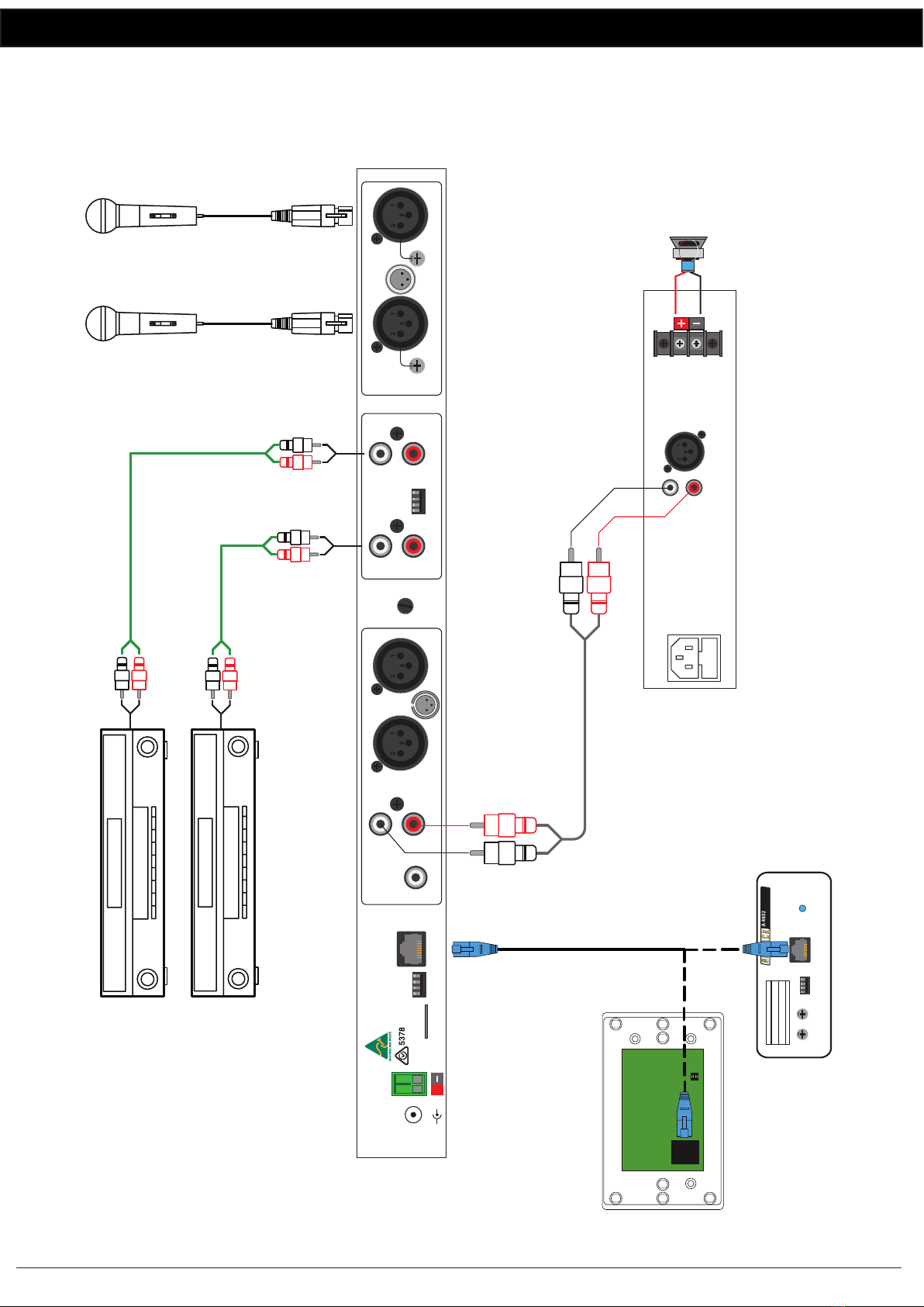
Output connectors: .......................3 pin XLR balanced
...............................Stereo RCA
INPUT CONNECTORS:
Mic: ..........................3 pin XLR balanced rear panel
...................6.35mm jack balanced front panel
Line inputs: .............................RCA stereo rear panel
............ 3.5mm stereo jack front panel
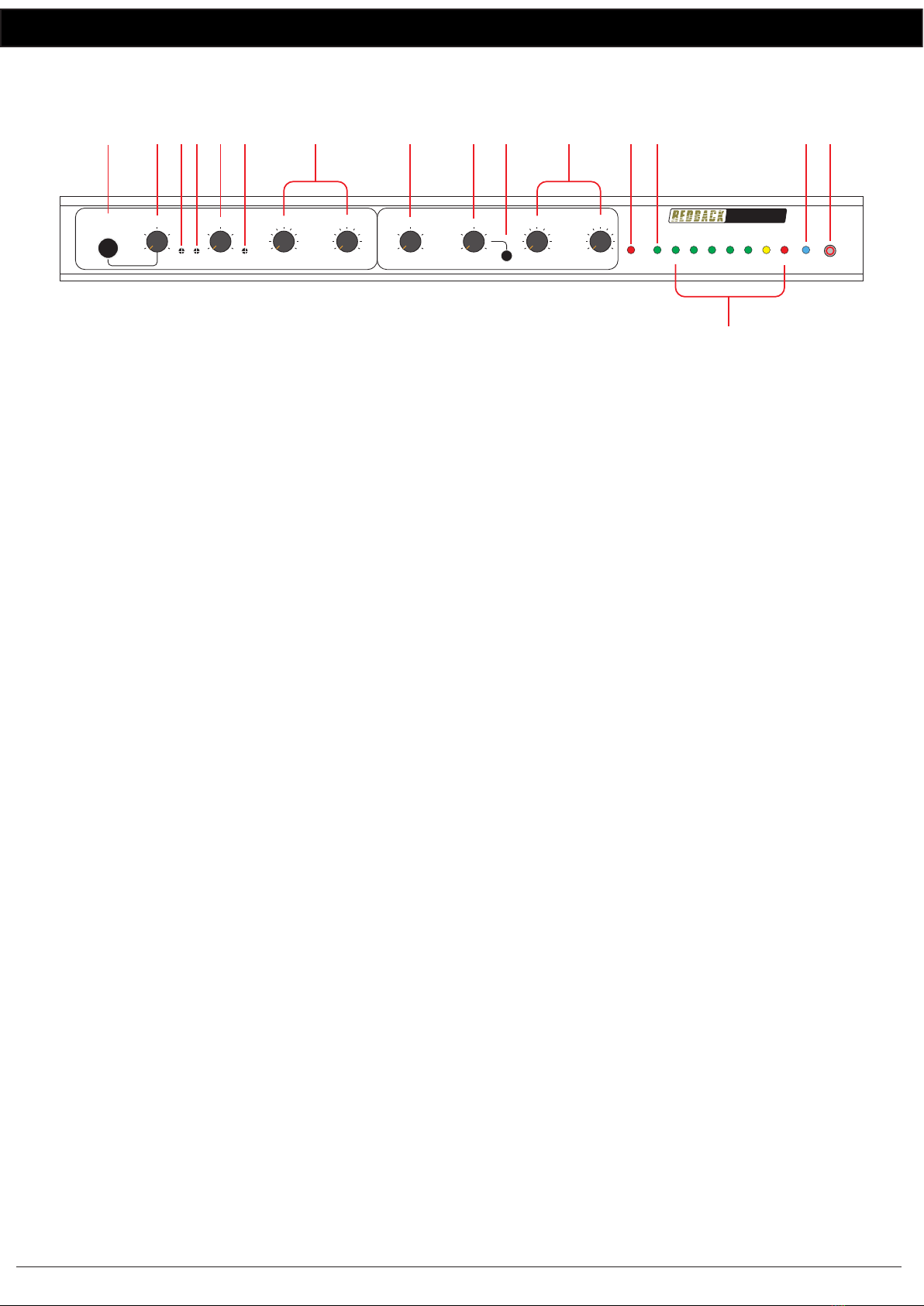
CONTROLS:
Mic inputs: ......................................................Volume
Line inputs: .....................................................Volume
Bass: ..................................................±12dB @ 100Hz
Treble: ................................................±12dB @ 10kHz
Master Volume: ......................................On rear panel
VOX sensitivity: ....................................On front panel
Mute level Aux 1 & 2: .......................... On front panel
Mic gain: ............................................... On rear panel
Indicators: ..............................................Power on LED
Power supply: .................................................24V DC
Protection:......................................internal polyswitch
Dimensions: ..........................482W x 175D x 44H mm
Weight: ..............................................................≈3kg
Colour:................................................................Black
7.0 TROUBLE SHOOTING
If the REDBACK A 4411 mixer fails to deliver the rated performance, check the following:
No Power, No Lights
The standby switch is used to turn the unit on. Make sure this switch has been pressed.
Make sure mains power switch is on at the wall.
Check the supplied plugpack is connected correctly.
DIP switch changes not effective
Turn the unit OFF before changing DIP switch settings. Settings become effective after power is returned.
8.0 FIRMWARE UPDATES
It is possible to update the rmware for both the A 4411 Mixer by downloading the relative update version from
www.altronics.com.au or redbackaudio.com.au if available.
To perform an update, follow these steps.
1) Download the Zip le from the website.
2) Insert a Micro SD card into your PC.
3) Extract the contents of the Zip le to the root folder of the Micro SD Card.
4) Rename the extracted .BIN le to update.BIN.
5) Remove the Micro SD card from the PC following windows safe card removal procedures.
6) With the power turned OFF, insert the Micro SD card into the back of the A 4411.
7) Turn the A 4411 ON. The unit will check the SD card and if an update is required the A 4411 will perform the update
automatically.
Other manuals for A 4931
2
This manual suits for next models
3
Table of contents
Other Redback Music Mixer manuals