www.redbackaudio.com.auRedback® Proudly Made In Australia4
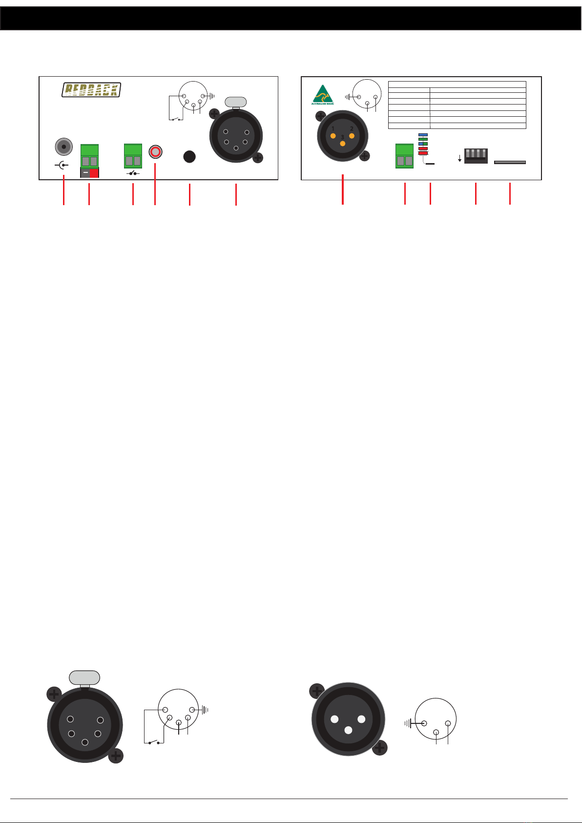
Redback® A 1760 Microphone Delay/Mic-Line Recorder
6.0 MICRO SD CARD
The A 1760 utilises a Micro SD card to store all recorded
audio, and for storage of the audio files to be used for the
Pre-Chime and Post-Chime tones/messages. The files are
stored in three folders, which are created by the A 1760 if
they are not present.
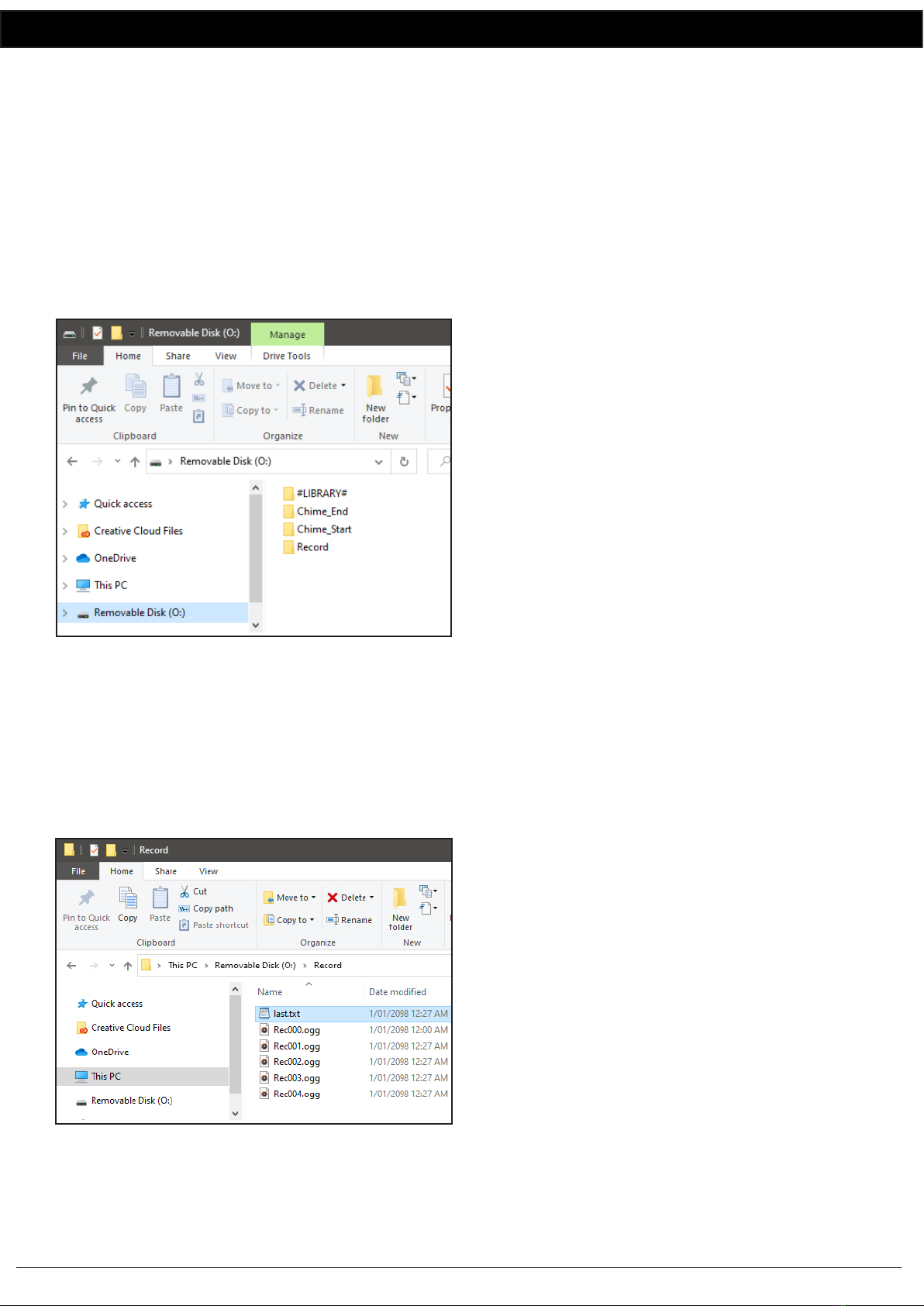
The folders are Record, Chime_End, Chime_Start and
#LIBRARY# as shown in figure 5 and are outlined below.
In order to access these folders, the Micro SD card will need
to be connected to a PC or laptop equipped with a Micro
SD card reader. If a Micro SD slot is not available then the
Altronics D 0371A USB Memory Card Reader or similar
would be suitable (not supplied).
Fig 5
Record: This folder contains all the recordings made by the
unit, whether they be recorded while in Audio Delay Mode
or Recorder Mode. The files are saved as “RecXXX.ogg”
where XXX is numbered 000-999 and increments each time
a new recording is made. Once the number of files over-
flows 999, the first file Rec000.oog will be overwritten and
increment.
The contents of the Record folder are shown in figure 6.
Fig 6
The file last.txt contains the number of the last completed
recording. If the file doesn’t exist, it is created and
recording starts from “Rec001.ogg”.
Note: There is no facility for the A 1760 to record the
correct date or time code on recorded files.
Chime_Start: This folder contains the audio file to be
played as the Pre-chime. The A 1760 must be in Delay
Mode with Option 1 active. (DIP SW 1 = OFF, SW 2 = OFF,
SW 3 = ON).
The file in this folder is played between the end of the re-
cording and the beginning of playback. This step is skipped
if no audio file is present in the folder.
An audio file in either .mp3, .ogg or .wav. formats needs to
be copied into this folder. Examples of suitable chime MP3
files are located in the #LIBRARY# folder. Some sub-formats
are unsupported, however the files generated by modern
systems (and this recorder) should all be valid.
If multiple files are present in the folder then the unit will
play the first it encounters. This is system dependant, but
will be constant. Only ASCII file names are supported.
Chime_End: This folder contains the audio file to be played
as the Post-chime and works in the same manner as the
Chime_Start. The A 1760 must be in Delay Mode with
Option 1 active. (DIP SW 1 = OFF, SW 2 = OFF, SW 3 = ON).
The audio file is played after the recording has completed
it’s playback. This step is skipped if no audio file is present
in the folder.
#LIBRARY#: This folder contains a host of sample MP3 files
which could be used for the Pre-chime or Post-chime.
6.0 FAULT FINDING & OPTIONS
Volume Control: If the volume of an audio file needs
adjusting, a file named “volume.txt” can be included in
the Record, Chime_Start or Chime_End folders. The file will
be used to set the volume level for playback (defaulting to
100%). The number in numerical text (eg 10, 25, 57 etc)
needs to be inserted into the text file as the first line of text.
Valid values are 0-100. Invalid values will default to 100%.
Fault Finding:
Attempting to remove the Micro SD card or power while
the unit is recording can result in undefined behaviour, and
may cause the unit to overwrite or corrupt previous record-
ings.
Always wait until the unit is in an Idle state (BLUE LED)
before removing the Micro SD card or power.
Flashing RED LED - An invalid operation condition has been
selected (currently selecting Mode 2 is the only thing
which triggers this).