Renogy RBM500-CA User manual

Version 3.0
BATTERY
MONITOR

01
Warning
Battery Safety
General Information
Please read this guide carefully to avoid incorrect connections that can cause the battery
monitor to malfunction and/or create a fire hazard. Disconnect the negative pole of the
battery before installation.
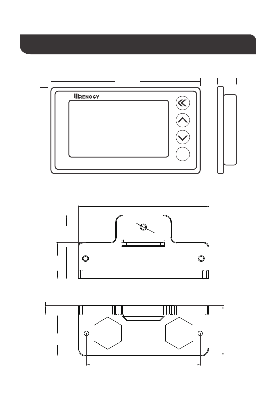
The Renogy Battery Monitor is a high precision device (also known as coulometer),
which can test the voltage, current, and capacity of a battery to help users know the
state of charge at any time. The Renogy Battery Monitor has a memory function which
allows users to set a low voltage capacity alarm. It is suitable for mobile and portable
equipment, e-bike, motorcycles, electric wheelchairs, and so on.
★The Renogy Battery Monitor is suitable for lithium batteries, lead acid batteries and
nickel-metal hydride batteries that have voltage from 10-120V.
★The Renogy Battery Monitor can't be exposed in the sun for a long time or in the
environment with large amounts of ultraviolet radiation when using or storing, in winter (<
-10℃) and summer (>60℃) otherwise the life span of the LCD will be shortened.
Do NOT let the positive (+) and negative (-) terminals of the battery touch each other.
Explosive battery gases may be present while charging. Be certain there is enough
ventilation to release the gases.
Be careful when working with large lead acid batteries. Wear eye protection and have
fresh water available in case there is contact with the battery acid.
It is the user’s responsibility to operate the equipment in a safe manner. Do not charge
batteries in an enclosed environment unless allowed by the manufacturer of the battery.
Never connect a load to a battery without using fuses or circuit breakers.
Please follow the battery manufacturer's safety instructions.

02
Identification of Parts
LCD Interface
Shielded Wire 20 AWG B+ Wire
500A Shunt/SamplerShunt/Sampler Holder
20ft (6m) 3ft (1m)

03
Dimension
ok
BATTERY MONITOR
99 mm
61 mm
2.4in
3.9in
3.3in
2.9in
0.9in
0.2in
1.1in
1.3in
1.7in
18 mm
0.7in
φ3.1mm
φ0.1in
24mm
42mm
85mm
6mm
27mm
33mm
74mm
M10, label the bolt size

04
Attention: Please connect as shown. The shunt must be series connected to the negative
circuit, DO NOT connect to the positive circuit.
The Renogy Battery Monitor is fixed by tabs, so it is easy to install. First, open a rectangular
orifice on your equipment panel according to the size. Then put The Renogy Battery
Monitor into the rectangular orifice, and make sure the tabs are locked.
Mounting
Installation
First, connect the Shunt in series to the negative circuit of your battery. B- of shunt connects
to B- of the battery. P- of shunt connects to P- of output and C- of charge.
Then take a wire of 0.3-0.75 mm². One end of the wire connects to positive of battery,
another end connects to B+ of Shunt (either one is ok).
Finally connect the Shunt to the Renogy Battery Monitor by the shielded wire and the
screen of the Renogy Battery Monitor display should turn on.
Connection/Setup
Connection diagram of Shunt/Sampler:
B- P-
P+(output+)
C-(charge-)
P-(output- )
Sampler
B+
B+
Battery
B-
+
-
Shielded wire
Panel
94mm
57mm
⑤⑥
④
③
⑧
⑨
①
⑦
②

05
Operation
Power on after the connection as shown in the figure. The battery voltage, current and
capacity percentage should be displayed on the screen. If there is no display, the power
should be turned of to check if the connection is correct. Then discharge or charge the
battery and check if the current value and the actual value are consistent.
If the error is large, check the wiring again.(Make sure that all current flowing through the
battery passes through the sampler.)
Use steps
1. Wiring and checking the current:
A. Enter the capacity setting interface and set the capacity value as large as possible. (For
example, it is set to 30Ah if the estimated value is 20Ah.);
B. Empty the battery pack and clear the capacity of electric meter to zero, and then charge
the battery pack;
C. The display's capacity is set to the CAP of the electric meter when fully charged.
The battery's effective capacity (CAP) needs to be set correctly before first use, see "Usage
Settings".
If the effective capacity of the battery is unknown, you need to follow the steps below:
2. Detection and Setting of Battery Effective Capacity:
Interface description
Present capatity Charge-discharge
indicator
Capacity percentage
Remaining time
Dynamic indication
Present voltage
Present current
Present power

06
Then it will work as expected and you don't need to do this later.
The capacity displayed on the electric meter is not the actual value of the battery after the
first use or replacement of the battery. And zero or full capacity operation is required:
3. Capacity Homing(The battery capacity is cleared or full capacity setting.):
A.Press and hold the button “ ” after the battery is discharged (empty) and the capacity
value is cleared to 0%;
B.Or Press and hold the button “ ” after the battery is full charged and the capacity
value is set to 100%.
ok
CAP: 0100.0Ah
Alarm: 000.0 Ah
Atten: 0.000 %
Full V: 000.0 V
Zero V: 000.0 V
PowOff: 000.0 V
Capacity setting
Line cursor setting
Exit settings / Exit the project line
Enter the project line / Select plus or minus
Previous row (setting value +1)
Next row (setting value -1)
Press and hold the button “ ” for 3 seconds to enter the settings
Full capacity voltage
Zero-capacity voltage
Shutdown voltage
Low capacity alarm
Battery attenuation ratio
ok
User settings

07
CAP
Effective capacity of battery:The default is 100Ah.Please set according to the actual
effective capacity of the battery pack, otherwise the capacity percentage display will be
incorrect;
Do not set Full V and Zero V without knowing the voltage characteristics of battery
pack (full voltage and vent voltage).
While charging the battery, the LCD screen's backlight will also be slowly flashing. In order
to turn off the backlight function,Long press front Keyboard can turn off the backlight,Long
press again Keyboard can Wake up the backlight.
The default of Full V and Zero V is 0V. It is invalid.
Zero V
Zero capacity voltage:The capacity value is automatically set to 0% if below this voltage. The
voltage value will flash, and the buzzer will alarm once per 10s if the discharge continues.
Full V
Full capacity voltage: When the voltage is higher than the set value, thecapacity will be
automatically set to 100%.
Alarm
Precautions:
Low capacity alarm:The percentage and battery symbol will flash, and the buzzer will sound
per 10s if below this capacity.
Atten
Battery attenuation ratio: After the battery Capacity cumulatively once per cycle,The capacity
value is automatically changed according to this ratio.
PowOff
Shutdown voltage:Backlight and LCD OFF and no display if below this capacity;

08
Troubleshooting
When the battery current is low the Renogy Battery Monitor will enter a low power (sleep
mode) and the backlight will turn off, press any button and the backlight will turn on for
10s.
When connecting the load, if the backlight is blinking, the B- and P- of the shunt are wired
inversely.
When the current changes frequently the data acquisition may produce an error, and it
may affect the accuracy.
When charging or discharging. The Renogy Battery Monitor will be working and the
capacity displayed will be real-time numbers.
Technical Specifications
Description Parameter
Working Voltage
Working dissipation
Standby dissipation
Voltage accuracy
Current accuracy
Capacity accuracy
Backlight on current(>50A)
Preset capacity value
Temperature range
Weight (LCD Interface)
Size (LCD Interface)
Shielded Wire
B+ Wire
10.0 - 120.0 V
10.0 - 15.0 mA
1.0 - 2.0 mA
±1.0 %
±1.0 %
±1.0 %
100 mA
0.1 - 9999.0 Ah
-10-60°C(14-140°F)
2.6 oz / 75 g
3.9*2.4*0.7 inch (9.9*6.1*1.8 cm)
20ft (6m)
3ft (1m)

Renogy reserves the right to change
the contents of this manual without notice.
RENOGY.COM
US 2775 E Philadelphia St, Ontario, CA 91761, USA
909-287-7111
www.renogy.com
https://www.renogy.cn
CN
400-6636-695
苏州高新区科技城培源路1号5号楼-4
CA https://ca.renogy.com
https://au.renogy.com
AU
JP https://www.renogy.jp
https://uk.renogy.com
UK
https://de.renogy.com
DE
Table of contents