Resodyn LabRAM ResonantAcoustic User manual

LabRAM Users Manual –Revised 3/18/11
Page 2
1 TABLE OF CONTENTS
1TABLE OF CONTENTS 2
2SAFETY INSTRUCTIONS 4
2.1 Types of Notices.................................................................................................. 3
2.2 General Safety Guidelines .................................................................................. 3
3DEFINITIONS 4
4INTRODUCTION TO THE LabRAM 5
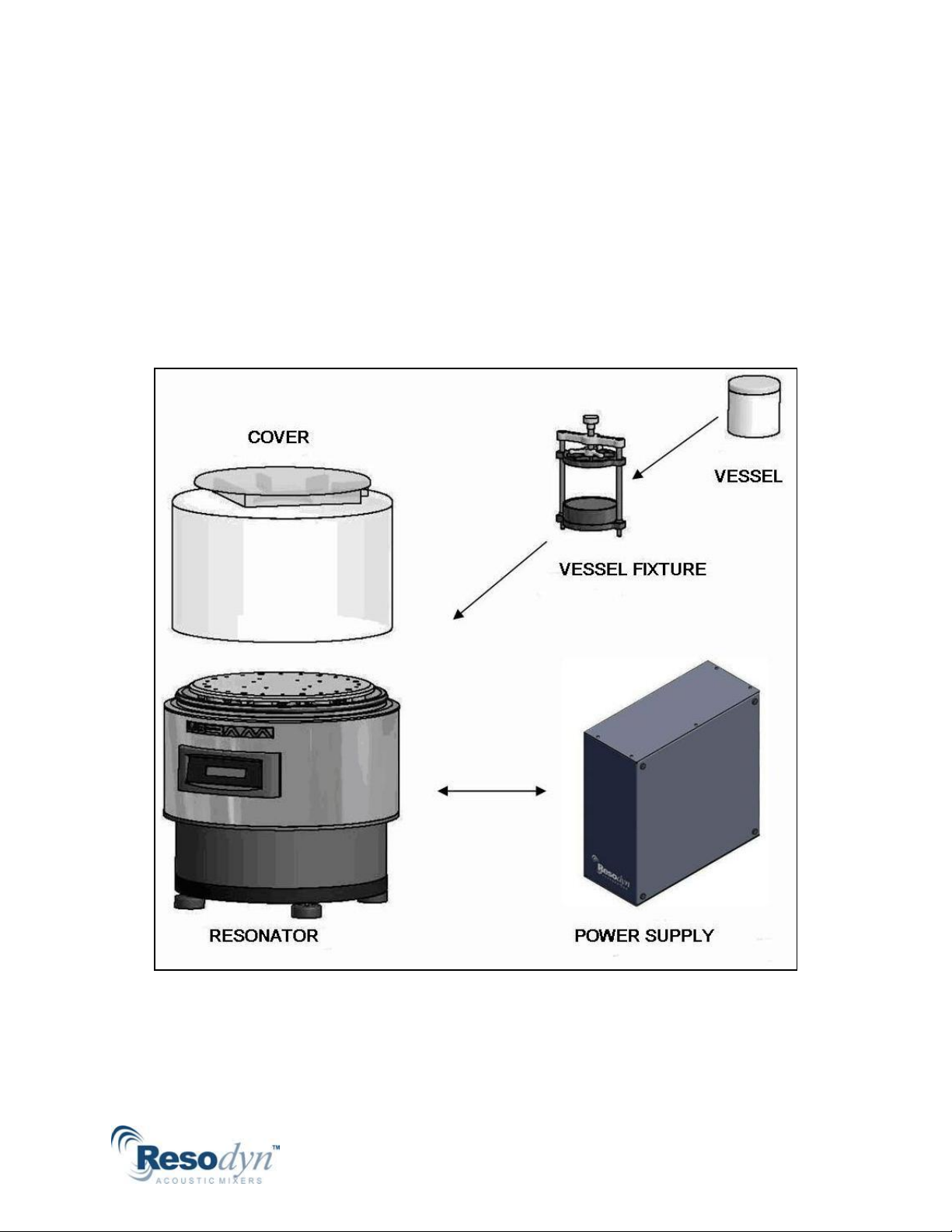
5MAJOR COMPONENTS 6
5.1 Overall Assembly ................................................................................................ 6
5.2 Resonator............................................................................................................ 7
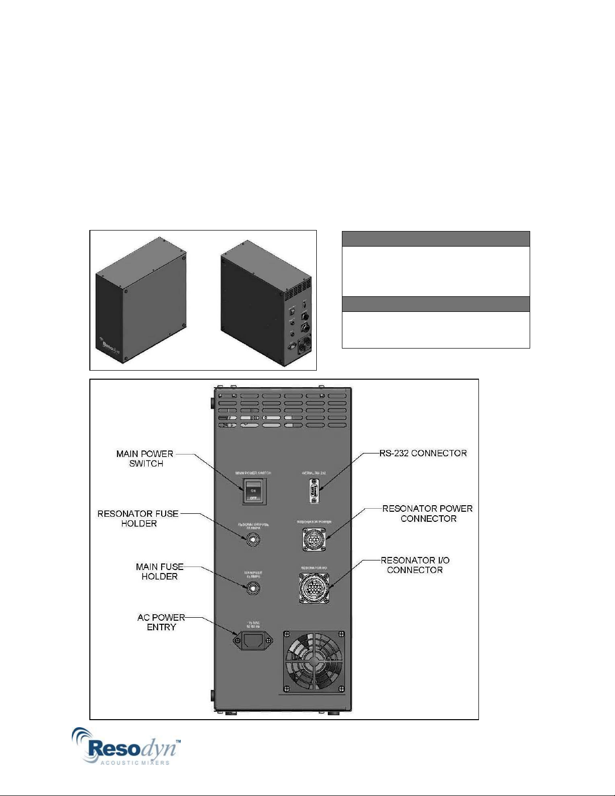
5.3 Power Supply and Control .................................................................................. 9
5.4 Standard Vessel Fixture and Vessels ................................................................ 11
6THEORY OF RAM MIXING 12
7SETUP 14
7.1 Prepare the Resonator...................................................................................... 14
7.2 Position the Power Supply................................................................................ 15
7.3 Connecting the Power Supply to the Resonator .............................................. 16
7.4 Attach the Hold-Down Fixture.......................................................................... 17
7.5 Install Vessel ..................................................................................................... 18
7.6 Install Cover ...................................................................................................... 19
8OPERATION 20
8.1 Turn on Power .................................................................................................. 20
8.2 User Interface Menus ....................................................................................... 21
8.3 Startup and Mixing Procedure.......................................................................... 22
8.4 Automatic Countdown Timer ........................................................................... 24
8.5 Error Handling................................................................................................... 25
9VACUUM OPTION 29
9.1 Introduction to the LabRAM Vacuum Option................................................... 29
9.2 Overall Assembly .............................................................................................. 29
9.3 Vacuum Set Up ................................................................................................. 30
9.4 Vacuum Operation............................................................................................ 32
9.5 Vacuum Maintenance....................................................................................... 33
9.6 Vacuum Technical Specifications...................................................................... 34
10 TROUBLE SHOOTING 34
11 MAINTENANCE 36
11.1 General Cleaning Instructions........................................................................... 36
11.2 Accelerometer Harness .................................................................................... 36
11.3 Driver Harness .................................................................................................. 37
12 TECHNICAL SPECIFICATIONS 38
12.1 General.............................................................................................................. 38
12.2 Resonator Enclosure......................................................................................... 39
12.3 Resonator Top Plate Fixture Mounting ............................................................ 40
12.4 Power and Control Supply ................................................................................ 41
12.5 Materials of Construction and Chemical Compatibility.................................... 42
13 SERVICE PLAN 45
14 ACCESSORIES 46

LabRAM Users Manual –Revised 3/18/11
Page 3
2 SAFETY INSTRUCTIONS
2.1 Types of Notices
Throughout this manual you will find various types of safety
notices. Their meanings are defined as:
Warning –Indicates the possibility of a hazardous situation which,
if not avoided, could result in injury or substantial property
damage.
Caution –Indicates the possibility of a hazardous situation which, if
not avoided, may result in minor injury or damage to the
equipment, or property.
Note –Emphasizes points, reminds you of something, or indicates
minor problems in the outcome of what you are doing.
2.2 General Safety Guidelines
CAUTION
Do not attempt to operate the Resonator with damaged or suspect vessels.
Note: Changes in noise level or frequency are common during
mixing operations. If you experience rattling, metal-on-metal, or
obnoxious noises, turn off the machine and examine equipment for
the cause.
WARNING
Do not attempt to override the SAFETY INTERLOCK SWITCH located on the Top Ring
of the Resonator. During operation, the Resonator Top Plate, Fixture, and Vessel,
vibrate up to 100 G’s. Serious bodily injury can occur if you come in contact with these
moving surfaces.

LabRAM Users Manual –Revised 3/18/11
Page 4
3 DEFINITIONS
RAM. ResonantAcoustic®Mixing
SMT. Smart Mixing Technology; closed loop resonance tracking
where the Power / Control Supply senses feedback from the mixer
and controls the resonant response.
RAMWare. Control software that runs on a Personal Computer
(P.C.) and provides control to, and feedback from, the mixing
process.
Damping. A measure of the instantaneous amount of energy
absorbed by your mix media while mixing.
Resonance. The point at which the system vibrates in the most
efficient manner.
Mix Media. A volume of fluid, powder, emulsion, or combination
thereof.
Mixing Regime. A description that identifies certain modes of
mixing. For example, a fluid will change regimes as it undergoes
acceleration, from an incompressible liquid with few headspace
bubbles in it, to a fluid that is fully integrated with the compressible
headspace such that the two are indistinguishable from each other.
Headspace. The volume of compressible air or gas space, above
the fluid in the vessel, that is un-occupied by the fluid.
G’s. A measure of acceleration expressed as a multiple of the
gravitational acceleration applied to the vessel and mix media
during mixing. For example, 10 G’s is 10 times the force of gravity.
Acceleration. A change in velocity with respect to time. Your mix
media mixes at different accelerations that are expressed in G’s.

LabRAM Users Manual –Revised 3/18/11
Page 5
Intensity. A non-dimensional unit of Driver energy applied to the
Resonator.
Vacuum. Some pressure less than atmospheric.
4 INTRODUCTION TO THE LabRAM
Your LabRAM mixer is based on Resodyn Corporation’s
ResonantAcoustic®Mixing (RAM) technology. RAM mixing is
distinctly different than conventional mixing methods such as
impeller agitation. Conventional methods work by producing bulk
fluid flow in a mixture. RAM brings to you a new paradigm in
mixing that is based on using acoustic energy to create flow in
liquids, slurries, and powders.
At the heart of your new RAM mixer is a resonant mechanical
system. The system creates high-intensity, low-frequency acoustic
waves in your mixing vessel that result in mixing.
This manual will provide you with the knowledge necessary to:
Understand the major components of your LabRAM
Introduce you to the theory of RAM mixing
Set up the LabRAM equipment
Operate the equipment
Trouble shoot common problems
Clean and maintain the equipment
Attach custom vessel fixtures and power requirements
Get your equipment serviced
Obtain additional accessories
Not covered in this manual are:
Repair of the mixer
Use of RAMWare
Note: RAMWare is a software package that runs on a P.C. and is
networked to the LabRAM. It is used to control multiple RAM units,
collect data and store mixing profiles. A separate user manual
describes the use of RAMWare.

LabRAM Users Manual –Revised 3/18/11
Page 6
5 MAJOR COMPONENTS
5.1 Overall Assembly
The overall assembly comprises: the Resonator, Cover, Umbilical
Cables and Power Supply.
Note: An optional Vessel Hold-down Fixture and a variety of vessel
sizes are available from Resodyn Acoustic Mixers; see the
ACCESSORIES Section 14 at the end of this Manual.

LabRAM Users Manual –Revised 3/18/11
Page 7
5.2 Resonator
The Resonator is the primary driver in your RAM mixer system.
Your vessel, containing your mix media, attaches to the Top Plate.
The Resonator, a powerful unit in a small package, works in a
resonant mode to provide efficient energy transfer to the mix media
in your vessel. Precise control over different mixing profiles is
provided through the user interface panel on the front of the unit.
Additional control, and feedback from your process, is available
using RAMWare software and a P.C.
CAUTION
The Resonator weighs approximately 130
lbs. The Lab Bench must be capable of
solidly supporting the Resonator. Use
care when moving.

LabRAM Users Manual –Revised 3/18/11
Page 8
Cover. The Cover is cast acrylic. Its purpose is to contain fluid and
debris if a vessel breaks during operation. A second purpose is to
prevent a person from touching moving parts while the mixer is
operating. It activates the safety interlock switch. The mixer will
not operate without the interlock switch activated and the Cover in
place.
User Interface. The User Interface is a membrane keypad with a
clear window revealing a Liquid Crystal Display (LCD). The LCD is
used to display the operating status of your mixer. The keypad is
used to start and stop the machine, and input operating parameters
such as Driver intensity and Frequency.
Power Switch. The Power Switch cycles power to the Resonator. It
is redundant to the power switch on the back of the power supply.
So, you may leave the power supply on continuously and turn
power on and off at the Resonator using this switch. Note: Both
power switches must be in the ON position for the machine to
operate.
Safety Interlock Switch. The Safety Interlock Switch prevents you
from operating the machine without the cover in place. When the
cover is installed properly, it depresses the Safety Interlock Switch
allowing the machine to run.
Enclosure. The Enclosure protects you from moving parts inside
the machine.
Input/Output Connectors. The Input/Output Connectors are used
with a cable harness to connect power and transmit signals
between the Resonator and the Power Supply. The Power
connector holds 7 pins; the I/O connector holds 16 pins.
Leveler Feet. The Leveler Feet may be adjusted to level the
Resonator Top Plate. They also provide additional vibration
isolation to your work bench.

LabRAM Users Manual –Revised 3/18/11
Page 9
5.3 Power Supply and Control
The Power Supply and Control is separate from the Resonator and
can be located remotely, in order to minimize space occupied on
your lab bench. The Power Supply provides power to the
Resonator. It is connected to the Resonator through two cable
harnesses and has its own power switch. Using precise closed
loop controls, The Power Supply also automatically holds the
Resonator in resonance while mixing.
CAUTION
The Power supply weighs
approximately 40 lbs and must be
located in a secure area away from
potential liquid spills.
CAUTION
The Power supply operates at 115
VAC, 15 amps, 50 to 60 Hz.

LabRAM Users Manual –Revised 3/18/11
Page 10
Main Power Switch. The Main Power Switch cycles power from the
A.C. Power Entry socket. The switch may be left ON continuously.
Power may then be switched ON or OFF at the Resonator switch.
Note: Both power switches must be in the ON position for the
machine to operate.
Resonator Fuse Holder. This holds a 10 amp, slow blow fuse, 3 Ag,
250 V.
Main Fuse Holder. This holds a 15 amp, slow blow fuse, 3Ag, 250
V.
A.C. Power Entry. This is a standard A.C. Power Entry socket. It is
rated for 115 VAC, 15 amps, 50 Hz to 60 Hz.
RS-232 Connector. This is a standard RS-232 port. It is used to
connect your mixer to a PC. RamWARE software, used on your PC,
is available to monitor and control your mix process from the PC.
Resonator Power Connector. This is a 7 pin connector. It is used
with a cable harness to connect power from the Power Supply to
the Resonator.
Resonator I/O Connector. This is a 16 pin connector. It is used
with a cable harness to connect I/O data between the Resonator
and the Power Supply.

LabRAM Users Manual –Revised 3/18/11
Page 11
5.4 Standard Vessel Fixture and Vessels
Vessels of various sizes and a Hold-down Fixture are available
through Resodyn Acoustic Mixers. Other vessel applications are
adaptable to the LabRAM system. We can design a custom Hold-
down Fixture to handle most any shape of vessel for your particular
mixing application. Engineering resources are available to assist
you on this; please see ACCESSORIES Section 14. The Top Plate
standard mounting hole pattern is shown in TECHNICAL
SPECIFICATIONS Section 12.3.
Vessel Spacer. The Vessel Spacer is used to accommodate various
vessel heights. When using shorter vessels, one or more spacers
are stacked together. That way, the vessel will be positioned within
the clamp stroke of the Hold-down knob.
Hold-down Knob. Turning the Hold-down Knob clamps the vessel
in place. The knob is coupled to an ACME thread which in turn is
connected to the Upper Base. Turning the knob raises and lowers
the Upper Base.
Jam Nut. The Jam Nut is used to lock the vessel in place. The Jam
Nut discourages the Hold-down knob from vibrating loose during
operation.

LabRAM Users Manual –Revised 3/18/11
Page 12
6 THEORY OF RAM MIXING
ResonantAcoustics®uses a proprietary method to create a
mechanical system, designed to operate at a resonant frequency of
the mechanical system. One advantage ResonantAcoustics®has
over other mixing systems is the use of high-intensity acoustic
energy. This is imparted on the vessel contents causing rapid
fluidization and dispersion, resulting in very rapid mixing. This
technology allows for considerable flexibility in the size and design
of the vessel used. In order to understand how to use the mixer, it
is necessary to explain how the contents in your mix vessel affect
the system.
Your mix vessel and its contents are termed the “Payload”. The
resonant mechanical system is the “Mixer”. Payloads are mixed at
the mixer system’s operating resonant frequency and a device
called the “Driver” controls that resonance. The Payload affects
the operating resonance in two ways: 1) Payload mass affects the
operating frequency of the mixer; 2) Payload damping affects the
Driver intensity required by the mixer.
1. Payload mass affects the operating frequency because, as the
payload mass increases, the operating frequency decreases.
Conversely, a lighter mass will produce a higher operating
frequency. Your vessel weight, volume of contents, and specific
gravity, are all components of the “static” payload mass. As the
payload is accelerated, its “dynamic” mass affects the frequency.
This dynamic mass may change during the mixing process and the
LabRAM will track the resonant frequency of the mixer as the
dynamic mass varies.
2. Payload damping affects the Driver intensity required to
accelerate the payload. Damping is a difficult number to predict.
However, a general understanding of what influences it, and how it
affects the system, will serve the purposes of this discussion.
Three factors affect damping; viscosity, head space, and fluid
acceleration. Higher damping requires a higher Driver intensity to
achieve a specific acceleration on the Payload.
Payload acceleration is a measure of the amount of acoustic
energy put into your mix media. It is measured in units of G’s. One
G = 9.81 m/s2; higher G’s = more acoustic energy. You will
determine how many G’s you need for your specific process as you
gain experience with the mixer. Remember that higher damped
payloads will absorb more acoustic energy than lower damped
payloads so they require higher Driver intensities to achieve the
same payload acceleration and G’s as lower damped payloads.
The Driver intensity is controlled through the user interface and is
explained in OPERATION Section 8.

LabRAM Users Manual –Revised 3/18/11
Page 13
Now that we’ve discussed how your payload affects the mixer, let’s
look at the mixing process. The mixer operates at a mechanical
frequency generally between 58 Hz and 65 Hz, and will accelerate a
payload up to 100 G’s.
Figure 1: Resonant response of the mix media
Figure 1 shows the resonant response of the RAM mixer to
variations in a payload. The solid black line represents a payload
that has been accelerated to 100 G’s. Its response is slightly over
61 Hz. Now let’s assume that the payload mass is constant but the
payload damping has increased. The dashed gray line shows how
the same Driver intensity will accelerate the payload to lower G’s
(40 G’s), still at 61 Hz because the Payload is absorbing more
acoustic energy. The dotted black line shows a resonant shift to a
higher frequency, slightly lower than 64 Hz. The shift is due to a
lower “dynamic” payload mass.
During the mixing operation, your mix media may transition
through different regime changes. A regime change also causes
the dynamic mass to change. Because a change in the dynamic

LabRAM Users Manual –Revised 3/18/11
Page 14
mass causes a shift in the resonant frequency, we have built in a
resonant tracking feature, “Smart Mixing Technology,” (SMT). SMT
controls the mixer and keeps it operating on the resonant peak,
even if the peak changes. You can also operate the mixer in a
manual mode by turning off SMT. This manual versatility is
provided because there may be situations where you choose to run
the machine manually, such as during start up, or very low
operating accelerations. Generally though, you will use the SMT
feature.
7 SETUP
7.1 Prepare the Resonator
Your LabRAM has been shipped with items to protect the unit during
shipment. You will need to remove these items before using the unit.
You will notice three urethane bumpers placed between the payload
and top ring. These are placed here to help prevent the Resonator
from moving during transit. Please remove these bumpers before
supplying power to the unit.
You will also notice a wire connected between two contacts on the
back of the machine on the Power Supply Connector. Please remove
this wire. Pull the wire gently and it will come off easily. This is also
in place to help prevent movement during transit.
Important: Please retain all of these items in the unlikely event that
the unit needs to be returned to the factory.
Once the bumpers and wire are removed, your unit is ready to set up
and operate.
Place the Resonator on a secure Lab work bench away from the
edges of the bench. The Lab bench must be capable of supporting
the Resonator solidly. Using a contractor’s level, adjust the 4
leveling feet until the Resonator sits level on the Lab bench.
CAUTION
The Resonator weighs 130 lbs. The Lab
Bench must be capable of solidly
supporting the Resonator.
CAUTION
The Bottom of the Resonator houses an
intake fan to dissipate heat while running.
The space between the bottom of the
Resonator and work bench must be free from
obstruction.

LabRAM Users Manual –Revised 3/18/11
Page 15
7.2 Position the Power Supply
Position the Power Supply
near the Resonator, under
your Lab work bench, in
order to maintain working
space on your bench. The Power Supply may also be placed on the
bench near the Resonator or on a separate shelf. However, the
supporting surface must be stable and must support the Power
Supply securely. Furthermore, it must be in a location away from
potential liquid spills. Standard 6’ cables are included and optional
12’ cables are available.
Figure 2 shows two ideal scenarios for positioning the Resonator
and Power Supply.
CAUTION
The Power supply weighs 40 lbs and must
be located in a secure position away from
potential liquid spills.
Figure 2: Positioning the Resonator and Power Supply

LabRAM Users Manual –Revised 3/18/11
Page 16
7.3 Connecting the Power Supply to the Resonator
To connect the Power
Supply to the
Resonator, refer to
Figure 3 and Figure 4.
Figure 4: Resonator connection
Connect the 7 Pin, Resonator Power Connector Harness, to the rear
of the Power Supply and the rear of the Resonator. Twist and
tighten the locking collars.
Connect the 16 Pin, Resonator I/O Connector Harness, to the rear
of the Power Supply and the rear of the Resonator. Twist and
tighten the locking collars.
Attach the AC power supply cable to the rear of the Power Supply
in the location shown and to an appropriate 115 volt, 15 amp,
source.
Figure 3: Power Supply Connection
Note: There is a
RS232, 9 pin sub D
connector. It is a
serial port that is
connected to a P.C. to
communicate when
RamWARE is used.

LabRAM Users Manual –Revised 3/18/11
Page 17
7.4 Attach the Hold-Down Fixture
Mounting holes for attaching the LabRAM Hold-Down Fixture, or a
custom fixture, are provided in the Top Plate of the Resonator.
Specific dimensions for the Top Plate mounting hole placements
are defined in TECHNICAL SPECIFICATIONS Section 12.3.
CAUTION
The ¼-20 Cap Screws must be
torque adjusted to 8 ft-lbs. Failure to
do so may result in the Fixture and
Vessel vibrating loose during
operation.
CAUTION
Be sure the power is “OFF” before
making any mechanical
adjustments or electrical
connections.
Figure 5: Attaching the Hold-Down Fixture
To attach the Hold-Down Fixture to the Resonator Top Plate refer to
Figure 5.
First, thread the two ¼-20 socket head cap screws into the Top
Plate mounting holes. The cap screws must pass through the Top
Cross Bar, Upper Base, Sleeves, Helical Washers and Lower Base
as shown.
Next, torque cap screws to 8 ft-lbs using a 3/16” hex-head tool.
NOTE: The Hold-Down Fixture is shipped with nuts placed on the
bottom of the ¼-20 socket head cap screws. These are to hold the
¼-20 SOCKET HEAD CAP SCREW
TOP PLATE

LabRAM Users Manual –Revised 3/18/11
Page 18
fixture together during shipment. Remove these two nuts. You
may then thread the two ¼-20 socket head cap screws into the Top
Plate.
7.5 Install Vessel
To install Resodyn Acoustic Mixers’supplied vessels into the
fixture refer to Figure 6.
Figure 6: Vessel in Hold-Down Fixture
Insert one of the Vessel Spacers (if required) into the bottom of the
fixture as shown.
Tighten down the Hold-Down Knob clock-wise at the top of the
fixture until snug.
Tighten the Jam Nut to lock the vessel into place.
CAUTION
The Hold-Down Knob and Jam Nut must be firmly seated in place. Failure
to do so may result in the Vessel vibrating loose during operation.

LabRAM Users Manual –Revised 3/18/11
Page 19
7.6 Install Cover
To install the Cover to the Resonator refer to Figure 7.
Figure 7: Installing the Resonator Cover
Install the Cover into the slot located on the Top Ring of the
Resonator.
Seat the Cover onto the Top Ring by firmly pressing down.
Be sure the Safety Interlock Switch located at the rear of the
Resonator is depressed. It will be depressed when the cover is
seated.
Note: The cover must be firmly seated in order to activate the
switch and allow the machine to operate.
WARNING
Do not attempt to override the SAFETY INTERLOCK SWITCH! During operation the
Resonator Top Plate, Fixture, and Vessel vibrate up to 100 G’s. Serious bodily injury
may occur if one comes into contact with these moving surfaces.
SAFTY
INTERLOCK
SWITCH
TOP
RING
COVER

LabRAM Users Manual –Revised 3/18/11
Page 20
8 OPERATION
8.1 Turn on Power
To turn on the power to the Power Supply and Resonator refer to
Figure 8.
Figure 8: Turning on the Power Supply and Resonator
Turn on the power to the Power Supply by toggling the rocker
switch on the rear of the Power Supply UP, to the “ON” position.
Turn on the power to the Resonator by toggling the rocker switch
on the front of the Resonator to the RIGHT, to the “ON” position.
Note: Both power switches must be in the ON position for the
machine to operate.
Note: If the Cover is removed while the Resonator is operating the
Resonator will shut down. To restart the Resonator, replace the
cover and then press the green “START” button on the User
Interface Keypad.
Table of contents