IMPORTANT SAFETY INSTRUCTIONS
READ AND SAVE THESEINSTRUCTIONS
!WARNING !
TO REDUCE THE RISK OF FIRE, ELECTRIC SHOCK
OR INJURY, OBSERVE THE FOLLOWING:
1. Read all the instructions carefully before installation,
operation or maintenance of the unit. Failure to comply
with instructions could result in personal injury and/or
property damage.
2. Installation of the unit and the corresponding electrical
wiring must be done by a qualified person and be in
accordance with all municipal and national electrical
codes and pertinent industry standards should be
verified before installation.
3. Use this unit only in the manner intended by the
manufacturer. If you have any questions, contact the
manufacturer.
4. Moving Parts, Disconnect Power supply before opening.
ensure that all the nuts and screws are securely
fastened before restarting the unit.
5. Before servicing or cleaning the unit, switch power off at
service panel and lock the service disconnecting means
to prevent power from being switched on accidentally.
When the service disconnecting means cannot be
locked, securely fasten a prominent warning device,
such as atag, to the service panel.
6. When cutting or drilling into wall or ceiling, make sure
that you do not damage electrical wiring and other
hidden utilities.
7. To reduce the risk of fire, use only metal ductwork.
Do not use any accessories not recommended by the
manufacturer.
8. When performing installation, servicing or cleaning
these unit, it is suggested to wear safety glasses and
gloves.
9. Do not use this unit for commercial purpose.
10. For residential use only. The unit mustbe grounded.
11. Do not install in acooking area.
12. This unit is not designed to exhaust combustion and/or
dilution air for fuel burning appliances.
!CAUTION !
1. Turn the unit OFF during construction or repair to avoid
filter blockage.
2. Exhaust air outside -Do not intake / exhaust air into
spaces within walls, crawl spaces, garage, or into attics.
3. Unit has to be installed in accordance to National and
Local Building Code.
4. When leaving house for along period of time (more than
two weeks), a responsible person should check if unit
operates adequately.
5. Published efficiencies are based on balanced air-flows
on supply and exhaust.
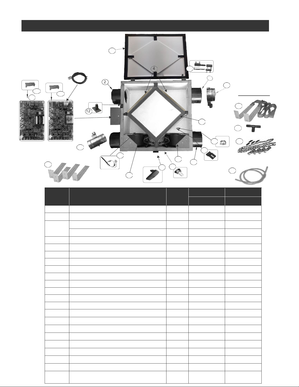
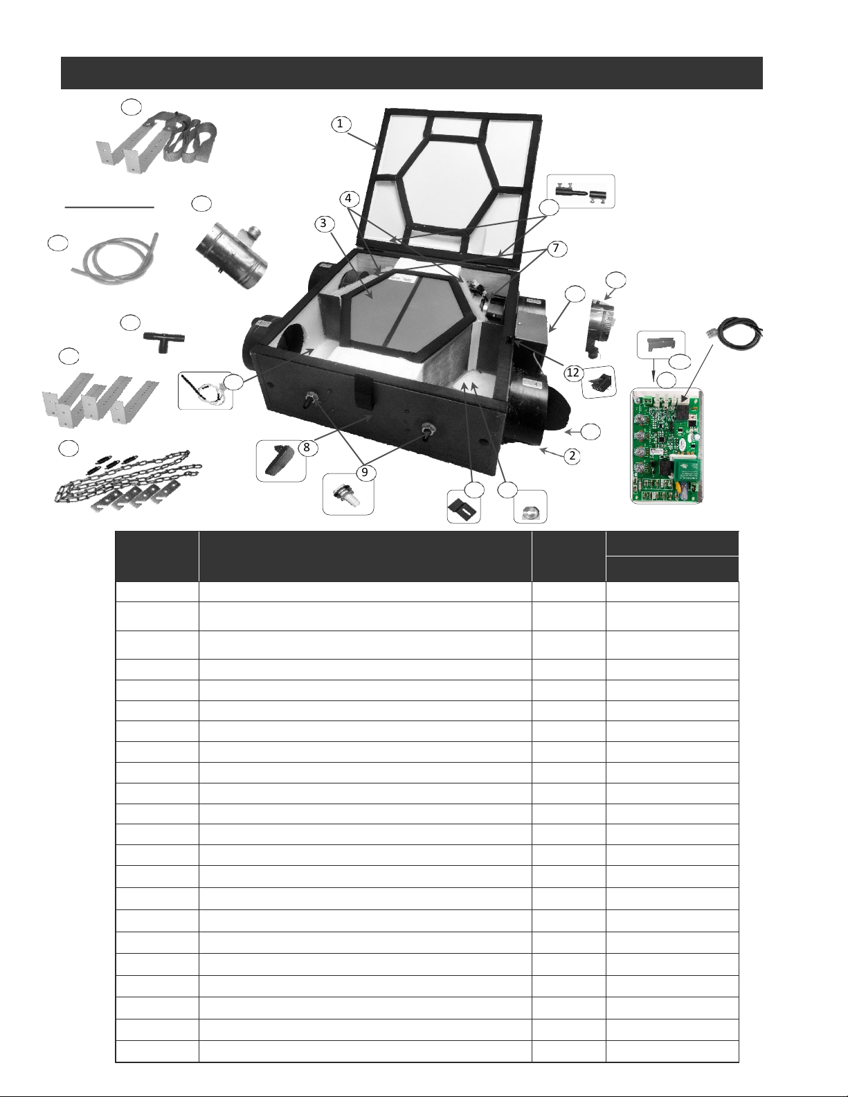
PACKAGING INSPECTION
Open the box and check to make sure all the parts and
accessories are present and in good condition. If you find
any parts missing or any shipping damage please contact
factory or our distributor immediately.
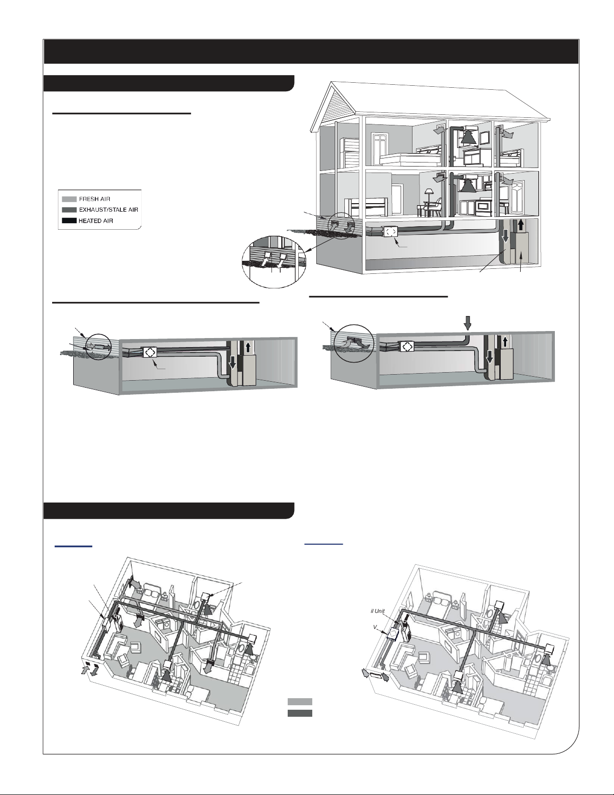
HRV and ERV Typical Installations
•-Fully Ducted System 8
- Furnace Return Air-duct connection
- Semi Ducted System
•Horizontal Vertical 9
•Single Vent & Access Door Installation 10
•Drain Connection 10
Air Flow Balancing
11
•Balancing Procedure
•Pitot Tube Air Flow Balancing 11
Maintenance
12
•Regular Maintenance
•Annual Maintenance 13
Troubleshooting
Climate Zone
13-14
14
CONTENTS
Parts List
1
•RERV-C100NF
•RHRV-CF100PECM 2
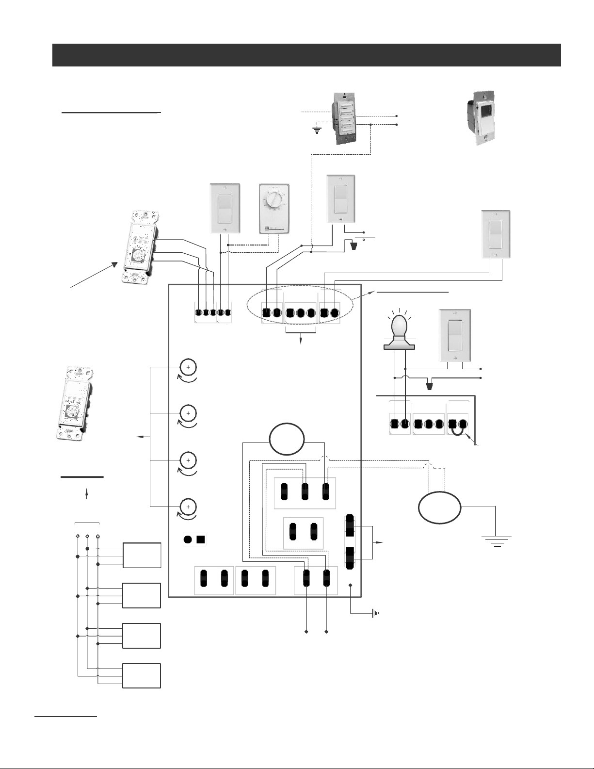
Wiring Diagram
•Control Board and Switches
•Furnace /Fan-Coil /Heat Pump Interlock
3-4-5
6-7
Standard Furnace Interlock Wiring
Alternate Furnace Interlock Wiring