Revolutions 21677 User manual

Owner’s Manual
Product:
Trademark:
Quantity:
Ceiling Fan
Revolutions
1 Piece
44285-01 r073113
Models 21677 Brushed Nickel
21678 White
Sprite Ceiling Fan

44285 r073113
1
Please read these instructions carefully before attempting to install this ceiling fan. It is also
advisable to keep these instructions in a safe place for future reference. Before installing and
using this ceiling fan, read the list of Do’s and Don'ts on Page 3.
Do not use the ceiling fan and open gas heating appliances in the same room at the same time. It
is important that the correct electrical connections are made and that the mounting plate is fitted
to an adequate ceiling support. Ceiling fans are heavy. So, it is important that they should be
suspended securely. If in any doubt about the installation of this product, consult a qualified
electrician.
This product must be installed in accordance with national building regulations.
When deciding on the location for your ceiling fan, make sure that there will be plenty of room
for the rotation of the fan blades and that no obstacles are likely to get in their way. The distance
between the fan blades and the floor should be at least 2.1 meters (7 feet).
Remove the upper polystyrene cover from the box. Take the motor out of the box and place it on
the polystyrene cover or on a soft, padded surface to protect it during the installation procedure.
Crosshead and slotted screwdrivers
Step ladder
Insulating tape
60W max BC Bulb or 13W Energy Saving Bulb (not included)
1. Unscrew the four screws on the ceiling canopy to release the mounting plate. (See Figure 1).
Secure the mounting plate to a ceiling joist, or equally secure ceiling structure using the two
wood fixing screws and washers supplied. The support for the mounting plate must be capable of
safely and securely holding the moving weight of the fan (See Figure 2).
Note: additional strengthening of the joist might be necessary.
2. For best fan performance and safety, ensure the mounting plate is fitted to a level ceiling joist
or ceiling support. If the mounting position is not level, hard packing material should be used to
make the plate level.
1. Engage one of the screw holes at the top of the ceiling canopy with the hook on the mounting
plate (See Figure 3 on the following page). With the fan suspended in this manner, you can now
make the appropriate electrical conections. See the CONNECTION TO THE LIGHTING
CIRCUIT section below. In addition, the Green Ground wire from the ball joint must be
connected to the Ground wires from the ceiling plate and main supply.
2. When the electrical connections have been made, take the fan off the hook. Slide the ceiling
canopy up the downrod, making sure that the ball joint groove engages with the ceiling canopy
entry hole tab. Slide the bayonet slots on the ceiling canopy onto the screws at either end of the
mounting plate, secure with the four screws provided (See Figure 4 on the following page).
ASSEMBLY & FITTING INSTRUCTIONS
INSTALLING THE FAN
CAUTION
IMPORTANT
LOCATION
TOOLS AND MATERIALS REQUIRED
UNPACKING
INSTALLING THE MOUNTING PLATE
Use Standard/Low-Profile Mounting to hang the fan
from a flat ceiling by a standard downrod (included).

44285 r073113
2
Ensure electricity is switched off at the main power supply before installing or maintaining this
fitting. The ceiling fan can be installed to operate in several different modes:
1. Fan controlled by pull switch, light controlled by pull switch.
2. Fan controlled by pull switch, light controlled by wall switch. (Not supplied).
3. Fan and light controlled by independent wall switches. (Not supplied).
Any switches connected to the ceiling fan must conform to the necessary local codes. If you are
unsure how to wire the ceiling fan, consult a qualified electrician. For the basic means of wiring
the ceiling fan (mode 1 above), use the following procedure:
White (Neutral) to the terminal marked N.
Black (Live) to the terminal marked L.
Green/Yellow or Green (Ground) to the terminal marked
Ensure that the Ground terminal of the canopy is securely connected to the Ground pole of the
terminal block.
Ensure that all electrical conections are tight and that no loose wire strands are left out of the
wire nuts.
Warning: If there are only two wires in your existing mains wiring, this means that there is no
Grounding. Under no circumstances should you wire this fitting without using a Grounded
connection. If you are not sure the electrical box and fan are grounded, contact a licensed
Electrician for advice. The ceiling fan must be grounded for safe operation.
The power supply must incorporate a 5 amp fuse and must have means of a double pole
disconnection with a separation of at least 3mm.
This ceiling fan must be installed in accordance with current national wiring regulations.
1. Attach the fan blades to the blade holder arms. Three supplied screws, washers, and nuts
should be used to securely attach each blade to each blade holder arm (See Figure 5).
2. Attach the other end of the blade holder arm to the fan motor housing using two supplied
screws and washers (pre-fitted on the bottom of motor housing), for each blade holder arm (See
Figure 6).
Note: These screws should be firmly installed, and the blade holder arm must sit completely
flush with the fan motor housing.
A pull chain switch controls the three speed settings. The operation of the switch follows this
order: OFF, HIGH SPEED, MEDIUM SPEED, and LOW SPEED (See Figure 7 on the next
page).
The fan must be switched off before this slide switch, located on the side of the switch housing,
is operated. (See Figure 7 on the next page).
Switch right for REVERSE winter operation.
Switch left for FORWARD summer operation.
1. Insert a 60W max BC bulb or a 13W energy saving bulb (not included) into the lampholders.
Do not use a higher wattage lamp.
2. Secure the lamp shade to the switch housing using the supplied screws. Be careful not to
over-tighten these screws—hand-tighten only (See Figure 7 on the next page).
3. The light is switched on and off by the using the pull chain switch located beneath the switch
housing (See Figure 7 on the next page).
Wipe with a soft, dry cloth, or use a soft brush to remove dust. Care should be taken that no
water or moisture gets into the ceiling fan. Do not use water to clean the ceiling fan.
Do not use metal polish or other abrasive cleaning materials on any part of the ceiling fan. A
small amount of furniture polish can be used to clean the fan blades. When cleaning the fan
blades, do not apply too much pressure on them. It is recommended that the ends of the fan
blades are supported when you clean them.
The fan motor is permanently lubricated. So, it does not require additional oil or maintenance.
INSTALLING THE BULBS AND LAMP SHADES
SPEED CONTROL
REVERSE CONTROL
CLEANING
CONNECTING THE LIGHT CIRCUIT
ASSEMBLING THE FAN BLADES

44285 r073113
3
Fan will not start
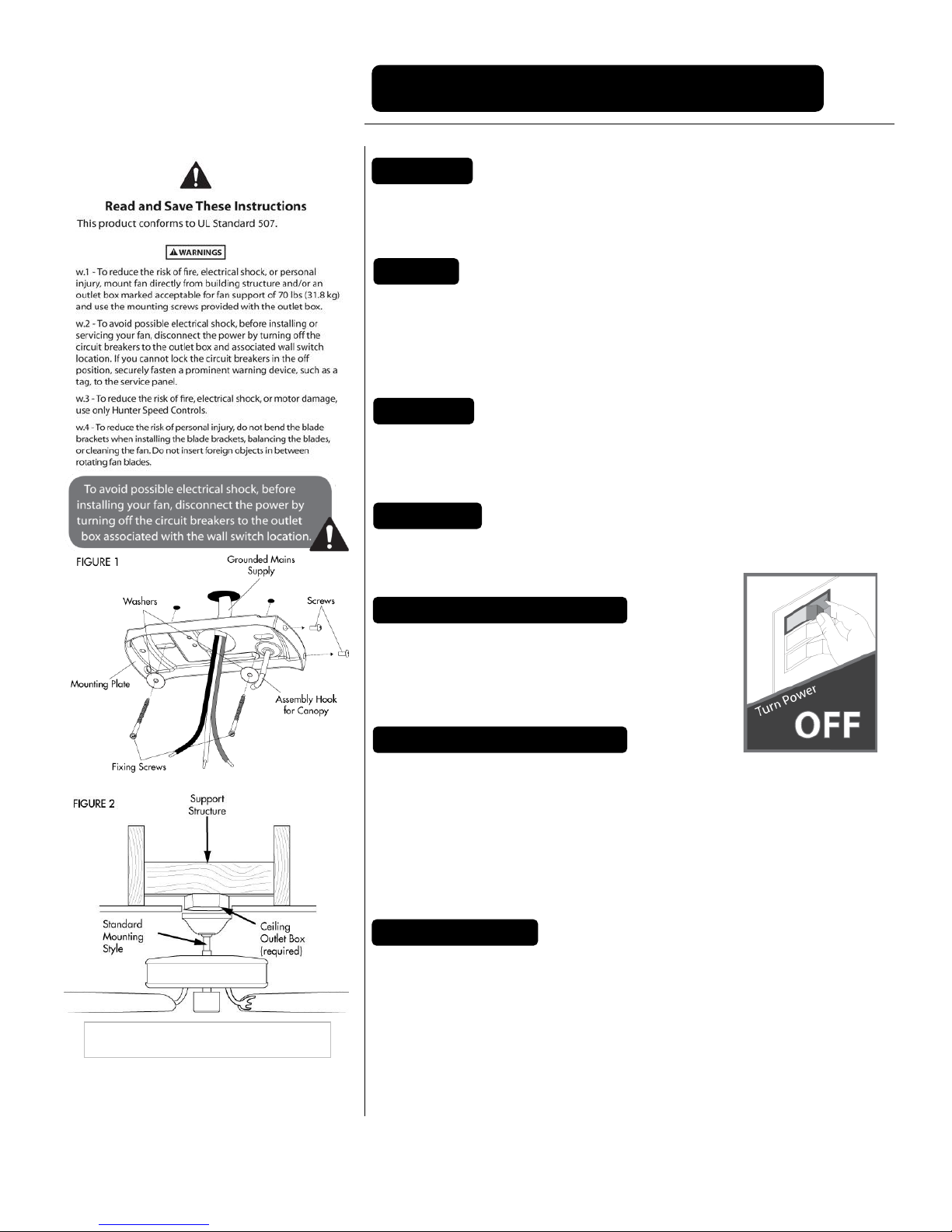
CAUTION: Make sure main power is switched off before you carry out these checks.
1. Check the main and branch circuit fuses or contact breakers.
2. Check that the power supply wires to the fan are secure.
3. Check that the reverse switch is firmly in the up or down position.
Fan sounds noisy
Allow a break-in period of 24 hours. Most noises associated with a new fan will disappear after
this period.
1. Check to make sure all screws to the fan motor housing are secure (but not overly tight).
2. Check mounting plate screws are tight and securely fitted to ceiling joist or ceiling support.
3. Check that the screws which attach the blade holder arms are tight.
4. Ensure that the screws holding the lamp shade are securely tightened. Check that the lamp is
properly fitted to the lampholder.
5. A dimmer switch should not be fitted to this ceiling fan. If this ceiling fan is connected to a
dimmer switch, it will make noises when the fan light is switched off. Remove the dimmer
switch.
Fan wobbles or shakes excessively
Note: a small amount of wobble is natural and should not be considered a problem.
All blades are weighed and grouped by weight. Natural wood varies in density which could
cause the fan to wobble even though all blades are weight matched. The following procedures
should eliminate most of the wobble. Check for wobble after each step.
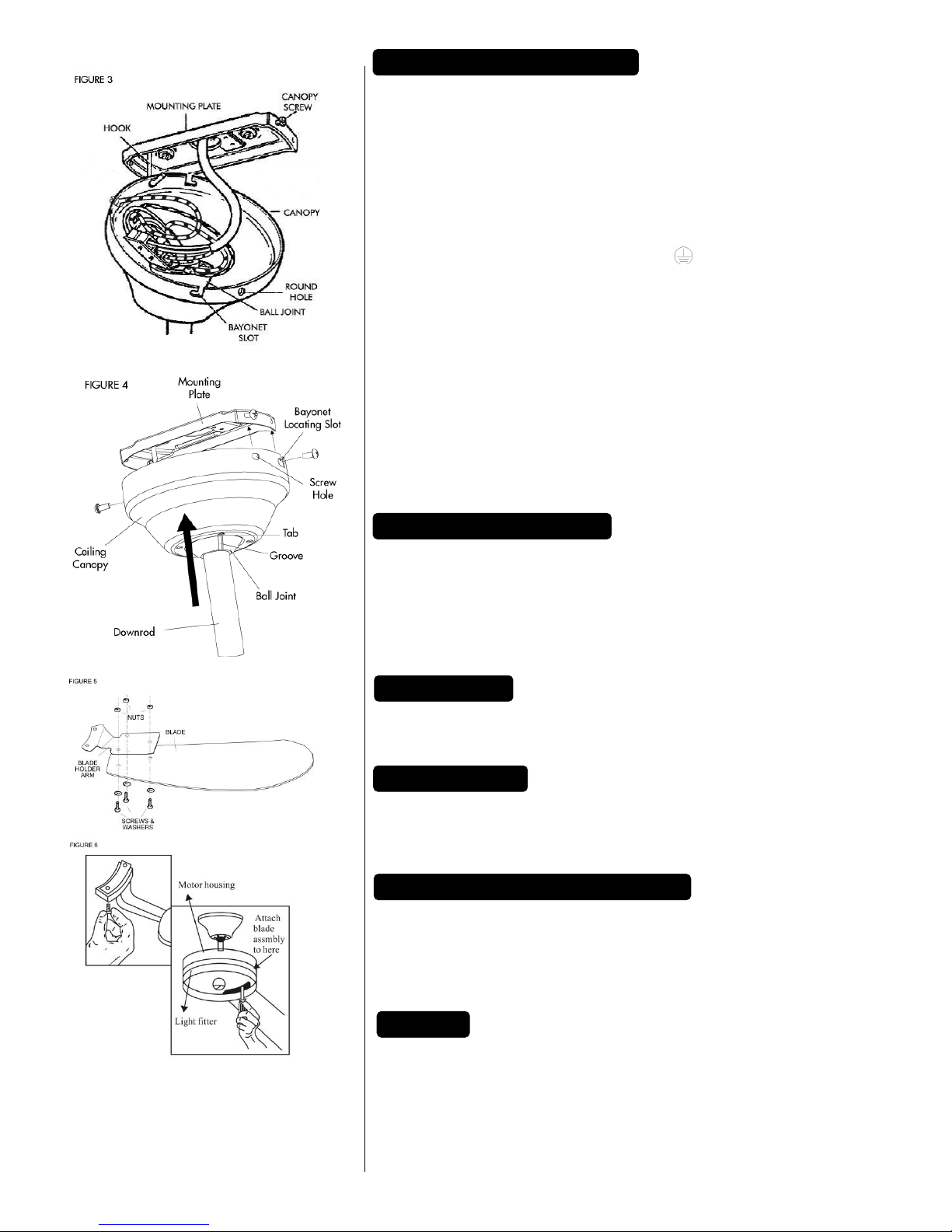
1. Check that fan blades are screwed firmly into the blade holder arms.
2. Check that all blade holder arms are tightened securely to the fan housing.
3. Most fan wobble problems are caused when blade tracking levels are unequal. Blade tracking
may be checked simply by using a length of timber. Place the timber vertically against the
ceiling and even with the outside leading edge of the blade. Mark the distance of the edge of the
blade to the ceiling. Turn the blades slowly by hand to check the remaining blades. If a blade is
not in alignment, the blade holder arm may be gently bent up or down to line up with the other
blades. Allow the fan to operate for ten minutes to see if the problem is resolved.
4. Make sure the mounting plate is securely fixed to the ceiling joist.
5. Ensure that the ball joint engages with the groove in the ceiling canopy.
Do ensure that the ceiling joist or ceiling support will hold the moving weight of the ceiling fan.
Do ensure that all electrical connections are in accordance with relevant safety and
government regulations.
Do use or consult a qualified electrician if you are uncertain about wiring the ceiling fan.
Do use a qualified electrician for installing the ceiling fan to a concrete ceiling.
Do switch off the fan before using the reverse switch. Failure to do so could damage the
fan.
Don't use the ceiling fan and open gas heating appliance in the same room at the same
time. Otherwise, harmful gases might be circulated.
Don't install in rooms where the distance between the floor and the blades is less than 2.1m
(7 ft). Allow at least 500 mm (1.6 ft.) between the blade tip and any wall or furnishings.
Don't install in bathrooms or areas where the fan may become wet.
Don't insert anything into the fan blades while they are rotating.
Don't use a dimmer switch with this ceiling fan. Doing so could damage the dimmer and
the fan.
Don't use this fan with any speed control device as it could be a fire risk.
Don't use the ceiling fan for any other purpose than that described in this instruction sheet.
Don't modify or alter the ceiling fan.
Fan 80W Light fitting 60W. Total 140W. 120V ~ 60Hz
Specifications subject to change without prior notice.
Do not attempt to repair this unit yourself. Repairs can only be made by qualified service
personnel. Repairs by unqualified persons will invalidate the guarantee and may result in
accident or injury.
SPECIFICATIONS
REPAIRS
TROUBLESHOOTING
DO
DON'T
IF IN DOUBT,
CONTACTA
QUALIFIED
ELECTRICIAN
This manual suits for next models
1
Table of contents
Other Revolutions Fan manuals
Popular Fan manuals by other brands

Eci Telecom
Eci Telecom Ribbon SBC 7000 Assembly

Monte Carlo Fan Company
Monte Carlo Fan Company Cupra 3CPR60 Series Owner's guide and installation manual

Westeel
Westeel 3HP Installation and operation manual

Hunter
Hunter 28496 Installating and operation manual

Ruck Ventilatoren
Ruck Ventilatoren EM 100L E2 01 Assembly instruction

Vent-A-Garage
Vent-A-Garage VG100 manual