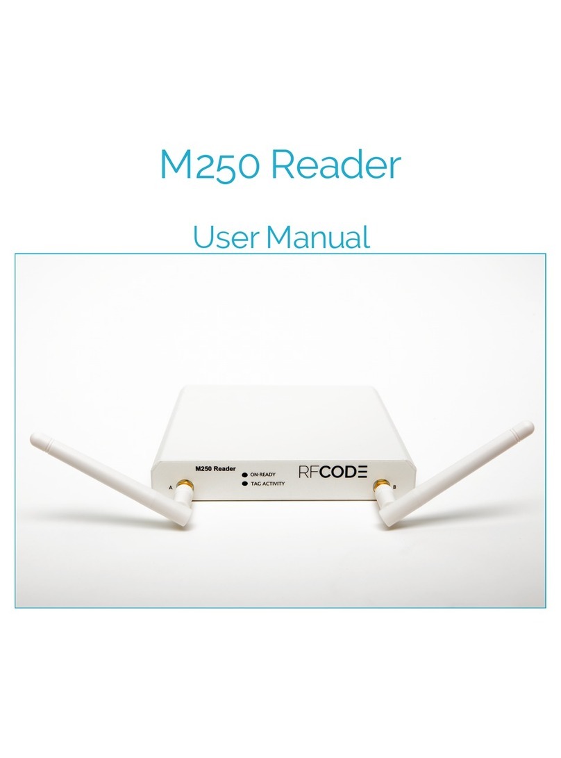
RF Code M250 Reader User manual

User Manual
M250 Reader

Page Intentionally Blank

PN01449 REV02 M250 Reader User Manual 3
Preface
4
Trademarks 4
Copyright Statement 4
FCC Compliance 5
CE Compliance 5
WEEE Compliance 5
M250 Reader 6
Introduction 6
Features 6
Contents 6
Hardware 7
LED Indicators 7
Connectors 7
Antennas 7
Environmental Conditions 8
Upgrading Reader Firmware 8
Tag Orientation 8
Antenna Orientation 8
Getting Started 9
ConguringtheReaderforDHCP 9
ConguringtheReaderforStaticIPAddressorDHCPwithUp-Connect 10
ReaderWeb-Console 11
Diagnostics 11
Tags11
Summary13
Conguration 14
NetworkConguration 14
SSLCerticateConguration 14
ReaderConguration 15
Users16
Up-Connect17
Time18
SerialPorts 19
Resetting The Reader 20
Mounting21
Warranty & Service 22
Limited Standard Warranty Terms 22
Standard Warranty Limitations 22
Obtaining Service & Support 22
RF Code Customer Support 22
Appendix 23
Using the M250 Reader with Windows 723
Contents

PN01449 REV02 M250 Reader User Manual 4
Trademarks
RF CodeTM and the RF Code logo are trademarks of RF Code, Inc. All other product names are copyright and regis-
tered trademarks or trade names of their respective owners.
Copyright Statement
Copyright ©2010-2015RFCode,Inc.AllRightsReserved.
Thisdocument,aswellasthehardwareandrmwaredescribedtherein,arefurnishedunderlicenseandmayonlybe
used or copied in accordance with the terms of such license. The information in these pages is furnished for infor-
mational use only, is subject to change without notice, and should not be construed as a commitment by RF Code,
Inc. RF Code assumes no responsibility or liability for any errors or inaccuracies that may appear in these pages.
RF Code reserves the right to make changes without further notice to any products herein. RF Code makes no war-
ranty, representation or guarantee regarding the suitability of its products for any particular purpose, nor does RF
Codeassumeanyliabilityarisingoutof theapplicationoruseof anyproduct,andspecicallydisclaimsanyandall
liability, including without limitation consequential or incidental damages.
Theuserof thissystemiscautionedthatanychangesormodicationstothissystem,notexpresslyapprovedbyRF
Code, Inc., could void the warranty.
Every effort has been made to supply complete and accurate information. However, RF Code assumes no responsi-
bility for its use, or for any infringements of patents or other rights of third parties, which would result.
RF Code, Inc.
9229 Waterford Centre Blvd.
Suite 500
Austin, TX 78758
www.rfcode.com
Preface

5
PN01449 REV02
FCC Compliance
ThisequipmenthasbeentestedandfoundtocomplywiththelimitsforaClassAdigitaldevice,pursuanttoPart15
of the FCC Rules. These limits are designed to provide reasonable protection against harmful interference when the
equipment is operated in a commercial environment. This equipment generates, uses, and can radiate radio frequency
energy and, if not installed and used in accordance with the instruction manual, may cause harmful interference to
radio communications. Operation of this equipment in a residential area is likely to cause harmful interference, in
which case the user will be required to correct the interference at his own expense.
RF Code is not responsible for any radio or television interference caused by using other than recommended cables
andconnectorsorbyunauthorizedchangesormodicationstothisequipment.Unauthorizedchangesormodica-
tions could void the user’s authority to operate the equipment.
ThisdevicecomplieswithPart15of theFCCrules.Operationissubjecttothefollowingtwoconditions:(1)thisde-
vicemaynotcauseharmfulinterference,and(2)thisdevicemustacceptanyinterferencereceived,includinginterfer-
ence that may cause undesired operation.
RF Code, Inc.
9229 Waterford Centre Blvd.
Suite 500
Austin, TX 78758
www.rfcode.com
Industry Canada Compliance Statement
ThisClassAdigitalapparatusmeetstherequirementsof theCanadianInterference-CausingEquipmentRegulations.
Avis de conformité à la réglementation d’Industrie Canada
Cet appareil numérique de la classe A respecte toutes les exigences du Règlement sur le matériel brouilleur du
Canada.
ThesystemisdesignedtooperatewithRFCodeRFIDTags–whoseoperatingfrequencyis433.92MHzwhichhave
beencertiedorareinthecerticationprocess.Thesedevicescomplywithpart15of theFCCrules.Operationis
subjecttothefollowingtwoconditions:
(1)thesedevicesmaynotcauseharmfulinterference,and
(2)thesedevicesmustacceptanyinterferencereceived,includinginterferencethatmaycauseundesiredoperation.
a.FCCID:P6F2005433forbeaconintervalsgreaterthan,orequalto10seconds.
b.FCCID:P6F433MHZforthesecuritytagwithbeaconintervalslessthan10seconds.
CE Compliance
This is a Class A product. In a domestic environment, this product may cause radio interference, in which case the
user may be required to take adequate measures. This equipment complies with the requirements relating to electro-
magneticcompatibility,EN55022classA,theessentialprotectionrequirementofCouncilDirective89/336/EEC
on the approximation of the laws of the Member States relating to electromagnetic compatibility.
WEEE Compliance
Do Not Dispose Product with Municipal Waste. Special Collection/Disposal Required.

PN01449 REV02 M250 Reader User Manual 6
Introduction
The433MHzM250readerinterpretsandreportstheradiofrequencymessagesemittedbyRFCodetags.Tag
transmissionscanbeprocessedinreal-timetoquicklylocateandidentifytaggedassetsorpersonnelindenedareas.
The M250 reader is compatible with wired and wireless networks for rapid integration into an organization’s IT
infrastructure. With a modular design and low price, the M250 Reader provides an economical solution to a wide
variety of asset tracking problems. RF Code’s patented communication protocols allow for very high tag densities.
Largepopulationsof tagscanbemonitoredusingasinglereader.TheM250reader’smaximumsensitivity(maximum
range)dependsupontheinstallation,locationandantennaconguration.Thismanualprovidesinstructionsforthe
M250 Reader setup and operation.
Features
Someof thefeaturesincludedintheM250Readerare:
• Instantaneous Tag Reporting
• OptionalWi-FiInterface
• High Throughput Performance Supports Large Tag Populations
• PatentedAnti-CollisionTechnologytoManageHighTagDensities
• Dual Channel Receiver Provides Tag Signal Reception Diversity
• Supportforupto32taggroupcodes
• Support for multiple connections over the same port
Contents
TheM250ReaderSystempackagecontentsare:
• M250 Reader
• Two¼-wavehelicalantennas
• ReaderCongurationUtilityCD
• 110/220VACto12VDCPowerSupplyandCord
M250 Reader

7
PN01449 REV02
Hardware
TheReaderishousedina5.79inch(14.7cm)by0.82inch(2.1cm)by5.75 inch(14.5cm)metalchassisandcontains
theinternalcomponentsof anRFIDReadercombinedwithconnectionstoallowforbothEthernetandWi-Fi
(optional)connectivity.
LED Indicators
There are two LEDs are mounted on the front of the M250 Reader.
• On-ReadyLED – This LED indicates the Reader has power applied through an external power adapter.
• Tag Activity LED–ThisLEDisusedfortwopurposes:(1)toshowthestatusoftheReaderwhileinstandby
modeand(2)toshowTagdetectionswhileinoperation.
1.Operating–TheTagActivityLEDashesintermittently,indicatingtheReaderhasreadoneormore
Tagseachtimeitashes.BecausetheReadercandecodeTagsfasterthanthelightcanbeturnedonand
off,asingleashmayindicatemorethanoneTagbeingdecoded.
2. Standby Mode – The Tag Activity LED turns on and off at a distinctive rate that indicates the Reader is
in standby mode.
There are four LEDs mounted on the back of the M250 Reader.
• Link/Activity – This LED indicates that the M250 Reader is connected to the network. The Link light stays
solidwhenthereisnonetworkactivityandasheswhenactivityispresent.
• 100/10–Whenon,thisLEDindicatesa100MBitEthernetconnection.Whenoff,thisLEDindicatesa
10MBitEthernetconnection.
• In Use – This LED indicates there is a connection to the M250 Reader and tag data is being read from the
reader.
• Status – This LED indicates that the M250 Reader is connected and receiving power.
Connectors
Several connectors are housed on the back of the M250 Reader.
• Power-DCbarreljack–allowsforconnectiontoanACpowerbrickthatoutputs12VDC.
• Power-DCterminalblock–allowsfordirectconnectiontoDCpowersources.Powerrequirementsare12to
24VDC.
Direct AC power connection is not supported for this device.
• Wi-Fi(notavailableontheStandardversion)–AWi-Fiantennaconnectionportallowsforconnectionofan
externalWi-FiantennathatisavailablewiththeWi-FiEnabledM250Reader.TheM250Readersupports
802.11band802.11gprotocols.
• Ethernet–RJ-45Ethernetjack.
• USB-A – Future expansion.
• USB-B–Aplugthatallowsforserialconnectivityforcongurationandtageventoutput.
Figure 1: Reader Data Connectors
Antennas
EachM250Readercomeswithtwo¼-wavehelicalantennas.Theseantennasprovideatagread-rangeof approxi-
mately100meters(openairwhennobackgroundRFinterferenceispresent).Thereader’smaximumsensitivity
(maximumrange)dependsupontheoperatingenvironment.

8PN01449 REV02
Environmental Conditions
The M250 Reader is approved for use within the temperature ranges set forth below.
• Operation:-20to+70degreesCelsius.
• Storage:-40to+80degreesCelsius.
Upgrading Reader Firmware
TheM250Readerhastheabilitytobeupdatedasnewrmwareisreleased.Toupgradethermware,launchthe
ReaderCongurationUtility,foundontheRFCodeReaderUtilitiesCD.Forinformationregardingthisprocess,
please refer to the ReaderCongurationUtilityUserManual also located on the CD. Firmware can also be upgraded
bydownloadingthelatestversionatthefollowingsupportsite:
http://www.rfcode.com/support_downloads
ItisvitaltheseupdatesbeobtaineddirectlyfromRFCodeoritsauthorizedpartners,sincetheselesdene
theoperationof theReaderandif corrupted,theleswillrendertheReaderinoperable.
Tag Considerations
Tagtransmissions,signalpropagationandread-rangearealldiminishedwhentagsaremountedveryclose
to the ground.
Read-rangewillvarywhentagsaremountedtometalobjects;ThesignalswillNOTpenetratesolidmetal.
Care should be taken when mounting tags near metal racks, rails or conveyor belts.
Tagperformanceisdiminishednearwater;signalsarenotpropagatedthroughwater.
Antenna Orientation
Figure 2: Antenna Positioning
!

9
PN01449 REV02
Each antenna post supplies an RF signal to the two parallel radio receivers in the M250 Reader. Antenna input im-
pedance is 50 ohms nominal.
Boththetypeof antennasusedandtheReaderrangesettingdeterminetheeffectivereadrange.ThenormalReader-
rangefeaturesaredenedusing¼-wavehelicalantennas.TheseantennasareappropriateformostReaderapplica-
tions. Optional antennas that offer diverse receiving properties or extend the range of the Reader are available for the
M250 Reader. Contact your RF Code reseller for more information.
The M250 Reader has two receiver channels that can operate independently or jointly to provide antenna diversity
forTagsignalreception..TheReadercanoperatewithoneantennaoneitherantennapost,butthebenetof re-
ceiver diversity is only obtained when both antennas are attached and pointed in different directions.
Toachievethebestreceiverdiversity:
• Antenna Angle from Reader – It is desirable to have the antennas positioned at different angles from
the Reader.
• Antenna Angle from Each Other–Antennasshouldbeat90-degreeanglesrelativetoeachother.
• Height–Asarule,thehigheraReaderispositionedabovethegroundoroor,thebettertheReader’s
detection range.
Do not allow antennas to overlap. Keep the antennas separated. Allowing the antennas to overlap reduces
the effectiveness of each antenna.
TominimizeRFinterference:
• Separation–Maintainaminimumof4-to-6-feetofseparationbetweentheReaderantennasand
potentialRFradiatorssuchascomputers,monitors,printersandelectronicofceequipment.RFemis-
sions from equipment local to the environment where the Reader is deployed can limit the Reader’s
effective read range.
• Height –DonotoperatetheReaderonorclosetotheoororground.Groundedandreective
metallic structures around the Reader and/or Tags affect the system’s performance. For best results, the
Reader should be mounted as high above the ground as reasonably possible.
LowlossSMAcoaxialextensioncablesmaybeusedtoextendtheantennasfromtheReader(available
separately).
Getting Started
Readersshouldbecongured(if necessary)priortobeinginstalledintheirpermanentlocations.Readersmustbe
conguredpriortouseif theIPaddressneedstobeassignedorif the“UpConnect”feature(explainedbelowin
thisdocument)istobeused.ThisisdonethroughtheReaderCongurationUtility which is available on the CD
typically included with the reader. This software is also available for download from the RF Code web page, http://
support.rfcode.com.Readersmaynotneedtobepre-conguredif theintentistouseDHCPforIPaddressassign-
ment.
Conguring the Reader for DHCP
By default the reader is set to DHCP and will be automatically assigned a DHCP address by a DHCP server if one
is available. If a DHCP server is present, the reader will attempt to request a hostname for DNS resolution as well.
Most, but not all DHCP servers are implemented in a way that will allow DNS resolution for DHCP clients that
requestaspecicname.TheM250willrequestahostnamesimilartorfcodexxxxxx.domainname.com where xxxxxx
are the last 6 digits of the MAC address of the wired Ethernet interface on the reader and domainname is your
domain that the DHCP server will provide. A label on the bottom of the reader lists the default hostname for each
reader.
!

10 PN01449 REV02
To congure the reader for DHCP:
1.AttachapowersourcetotheM250Reader(ACpowerbrick,DCpower,orPowerOverEthernetcable).
2. Attach an Ethernet cable to the Ethernet port of the M250 Reader and to an available network port on the
switch.
Forinitialconguration,theM250Readermustbeattachedtoanetworkportthatisonthesame
subnet as the PC that you are using to connect to the M250 Reader with.
3.Open a web browser window and type http://rfcodexxxxxx.domainname.com where rfcodexxxxxx is the de-
fault hostname listed on the bottom of the reader and domainname is the domain handed out by the DHCP
server.
4. IfyouareabletobrowsetotheM250Reader,thenDHCPworkedproperly.Youmaycongurefeatures
likeUp-Connect,conguresecurityorusethewebbaseddiagnostics.Ifthereaderwasnotfound,thenyour
DHCP server probably does not support hostname resolution and you will need to use a static IP address to
connectthereadertoyournetworkoralternatelycongure“Up-Connect”toconnectyourreadertoyour
RFIDapplication.Usetheinstructionsbelow(ConguringtheReaderforStaticIPAddressorDHCPwith
Up Connect)tocongureyourM250Reader.
Conguring the Reader for Static IP Address or DHCP with Up-Connect
1.ThemostreliablewaytocongureanM250readerisviaitsUSB-Bserialport.Installthereaderconguration
utilityonthePCbeingusedtocongurethereader.TheCDshouldremainintheCDROMdriveduringthe
install.
2. ConnectthereadertotheUSBport.Dependingonwhatdeviceyouhave,thismayrequireaUSB-AtoUSB-
Bcable(notincluded).AUSBcablecanbepurchasedatanelectronicsstoreorbigboxgeneralretailer.
USB-AtoUSB-BcableisincludedinRFCodepilotpacks
3.When prompted install the RFCUSB.inf driver thatislocatedinthecongurationutilityfolderoftheCD-
ROM.
4. RunthecongurationutilityandselectLocal as the connection method. The M250 Reader should be seen
on one of the COM ports listed. Select the COM port and click Next. You may change any setting in the
congurationtabsincludingtheIPaddressandUp-Connectsettings.YoumustclickSave Changes so that
thecongurationissavedtothereader.
5. Once a static IP is entered you should be able to connect to the M250 Reader with a web browser. If you
wishtouseDHCP,theReaderCongurationUtilitywillalsoreporttheIPaddressthathasbeenassignedto
thereader.However,thisaddressmaychange,soitisrecommendedthatyouutilizetheUp-Connectfeature
to connect the M250 Reader to the RFID software application.
If the M250 Reader is provided with wireless networking the Ethernet interface should be disabled
after the wireless interface is connected. While both interfaces may be enabled at the same time,
only one will be routable.
6. Attachtheprovided¼-wavehelicalantennasensuringproperstepshavebeentakentomaximizedesired
read-rangethroughantennaorientation(PleaserefertotheAntenna Orientationsectionofthisdocument).
7. Mount the M250 Reader using the process described in the Mounting section of this document.
8. ConguretheM250ReadertosenddatatoasoftwaresystemsuchasRFCode’sAsset Manager.
Please refer to the ReaderCongurationUtilityUserManualforfurtherinstructiononusingtheReaderCongura-
tionUtility.OnceyouhaveconguredtheM250ReaderwiththeReaderCongurationUtility,youmayaccessthe
M250ReaderdirectlybyaccessingtheReaderWeb-consoletoperformfurtherdiagnosticandcongurationtasks.
(PleaserefertotheReaderWeb-consolesectionof thisdocument.)
To obtain Tag data or customize the way the M250 Reader sends Tag data to your software ap-
plication please refer to the Reader APIdocumentavailableontheRFCodewebsite:.
http://support.rfcode.com

11
PN01449 REV02
Reader Web-Console
OnceanIPaddresshasbeenassignedtotheM250ReaderusingtheReaderCongurationUtilitysoftware,the
ReaderWeb-ConsolecanbeaccessedtogiveyouadirectconnectiontotheReader.ToaccesstheReaderWeb-Con-
sole, open a web browser and type the IP address of the reader in the URL address bar. The main console screen will
appear.IfyouconguredausernameandapasswordwiththeReaderCongurationUtility,youmaybeprompted
forthisinformationbeforeyouwillbeabletoaccesstheReaderWeb-Console.
Figure 3: Reader Web-Console
TherearetwomaintasksavailabletoyouintheReaderWeb-Console:DiagnosticsandConguration.
Diagnostics
WithintheDiagnosticstask,therearethreesub-tasksthatwillallowyoutoassesstheconditionsofthereader.
Tags
TheTagssub-taskcanbeaccessedbynavigatingtoDiagnostics > Tags.Thissub-taskisusedasavericationtool
to ensure that the Reader is online and detecting tags.
Add A Group Code
To add a group code, click the Add buttonandawindowwillappear.Enteragroupcodeandtreatmentcode(see
below)totesttheReaderwith.ClicktheOK button to add the Tag Group. If your reader is online and reading tags
properly you should begin to see tag data in the main task screen.
AllRFCodetagsaredenedasbeingmembersof aspecicgroup,andhaveauniquetagIDnumber
within that group. The group code is a string of 6 letters and is assigned by RF Code. Each group code is
uniqueforagiventagtype.WhenanRFCodereaderiscongured,itcanbesuppliedwithupto16group
codes. Each group code has a corresponding treatment code. The treatment code instructs the application
software how to interpret the payload data for each tag event within that group code. RF Code tags have
theabilitytotransmitvarioustypesof datawithintheirradiofrequencybeaconssuchasagsforvarious
sensors including for motion, panic, tamper, infrared location, humidity, pressure, temperature, and low bat-
teryamongstothers.Thegroupcodeandunique,numerictagIDareprintedonalabelafxedtoeachtag.
Sub Tasks
Task Panes
Main Tasks
Links

12 PN01449 REV02
Figure 4: Group ID, Tag ID, and Treatment Code Location
Figure 5: Example Tag Data in Tags Sub-Task
2sM 10sB
M100-iMoo-04A
Group Code Tag ID Treatment Code

13
PN01449 REV02
Summary
TheSummarysub-taskcanbeaccessedbynavigatingtoDiagnostics > Summary.Thissub-taskisavailableto
provideareportofversion,model,IPaddress,etc.informationthathasbeenconguredfortheReader.
Figure 6: Summary Sub-Task
There is also an option to reboot the Reader from the Summary screen. This can be done by selecting the Reboot
button.Youwillbepromptedwithadialogboxtoconrmifyouwanttorebootthereader.Ifyouwouldliketo
reboot the reader, select the Reboot button. If you want to opt out, select the Don’t Reboot button.
Tools
TheToolssub-taskcanbeaccessedbynavigatingtoDiagnostics>Tools.Thissub-taskisavailabletotestreader
connection with a server or to reboot the reader.
Ping a Server
Topingaserver,typeintheHostnameoftheserverandchooseaProtocolfromthedropdownlist(Both,IPV4or
IPV6)andclickthePingbutton.
Reboot the Reader
TorebootatheReader,clicktheRebootbuttonandconrmthereboot.
Figure 7: Tools Sub-Task

14 PN01449 REV02
Conguration
WithintheCongurationtask,therearevesub-tasksthatwillallowyoutomodifysettingsthatwereinitiallycong-
uredusingtheReaderCongurationUtility:NetworkConguration,ReaderConguration,Users,Up-Connect,and
Time.
Network Congurations
TheNetworkCongurationsub-taskcanbeaccessedbynavigatingtoConguration > Network Conguration.
Withinthissub-taskyoumayviewandmodifythedifferenttypesofnetworkcongurationsyouhavesetupforthe
Reader. Please refer to the ReaderCongurationUtilityManualformoreinformationregardingspecicnetwork
congurationtasks.
SSL Certicate Conguration
Bydefault,whenHTTPSisenabled,aself-signed10-yearSSLcerticateisgeneratedsothatcommunicationon
HTTPSportisencrypted.Tocommunicatewithbothencryptionandauthentication,anSSLcerticatemustbe
digitallysignedbyawell-knowncerticateauthority(CA).PleasecontactyourNetworkorSystemAdministratorfor
obtainingasignedSSLCerticate.
ToconguretheM250ReaderwiththeSSLCerticateperformthefollowingsteps:
1.Obtainaprivatekeyusingapreferredtooloracerticateauthoritymayprovidethisservice.Pleasearchive
thekeyandleinasafeplaceforsecuritypurposes.ThiskeywillbeneededforSSLcerticateconguration
later.
2. ACerticateSigningRequest(CSR)isgeneratedbasedontheprivatekey.
3.SubmittheCSRtoacerticateauthority.
4. ThecerticateauthorityissuesanSSLcerticatebasedontheCSRandinaPEMformat.
5. OnceasignedSSLcerticateisobtainedfromCA,importittotheM250Reader:
6. CopytheSSLcerticateportionfrom“BEGINCERTIFICATE”to“ENDCERTIFICATE”fromthePEM
andpasteitintothe“SSLCerticate”eld.
7. Copytheprivatekeyandpasteitto“SSLPrivateKey”eld.
8. Click the Save ChangesbuttonforthesignedSSLcerticatetotakeeffect.
IfasignedSSLcerticatecongurationisnotsuccessful(forexampleiftheSSLCerticateand
theSSLPrivateKeydonotmatch)theM250Reader’sself-signedcerticatewilltakeplace.

15
PN01449 REV02
Figure 8: Network Conguration Sub-Task
Toensurethatanymodiedsettingsareimplemented,clicktheSaveChangesbutton.
Reader Conguration
TheReaderCongurationsub-taskcanbeaccessedbynavigatingtoConguration > Reader Conguration.
Withinthissub-taskyoumayviewandadjusttheNoiseFloorlevelforChannelAandChannelBoftheReader.
Figure 9: Reader Conguration Sub-Task
• Channel A Dynamic Noise Floor -Whenthisboxischecked,thenoiseoorforthischannelisadjusted
automatically.
• Channel A Noise Floor -EnteravaluetosetthenoiseoorforchannelAantenna.
• Channel B Dynamic Noise Floor -Whenthisboxischecked,thenoiseoorforthischannelisadjusted
automatically.
• Channel B Noise Floor-EnteravaluetosetthenoiseoorforchannelBantenna.
Click the Save Changes button when you have completed your adjustments to the Reader settings.

16 PN01449 REV02
Users
TheUserssub-taskcanbeaccessedbynavigatingtoConguration > Users.Thissub-taskcanbeusedtoadduser
authentication to the M250 Reader.
Figure 10: Users Sub-Task
Add a User
• To add a user, click the New button.
• Enterausername,password,conrmthepasswordandselectauserrole.
• Administrator-hascompleteaccessandcontroloftheCongurationandDiagnostictask
• CongurationView-hasviewonlyaccesstotheCongurationtaskandcanutilizetheDiagnostics
tasks
• EventView-onlyhasaccesstotheDiagnosticstasksoftheReader
• Click the Save Changes button.
TherstuserthatmustbecreatedistheAdminuser,sotheuserrolewilldefaulttoAdministrator.
Delete a User
To delete a user, select the user from the list that you wish to delete and click the Delete button.

17
PN01449 REV02
Up-Connect
TheUp-Connectsub-taskcanbeaccessedbynavigatingtoConguration > Up Connect.Thissub-taskallowsfor
readercommunicationwithZoneManagerstobemore“rewallfriendly”.Whenthisoptionisselected,theM250
ReaderisconguredtoinitiatethecontactwiththeZoneManagerratherthanrequiringthataccessbegrantedto
allowtheZoneManagertoconnecttoreadersbehindarewall.
Figure 11: Up Connect Sub-Task
ConguringUp-Connect
ToaddanUp-ConnectConguration,clicktheNewbutton.PopulatethefollowingeldsandclicktheSave
Changes button.
• ID-EnteranamefortheUpConnectconguration.
• Enabled-CheckthisboxtoenablethereadertoupconnecttoaZoneManager.
• Hostname-InputtheIPaddressoftheZoneManagerthatthereadershouldconnectto.
• Port-InputtheportnumberoverwhichthereaderwillcommunicatewiththeZoneManager.
• Up Connect ID/Password -InputandverifyareaderIDandpasswordthatwillbeutilizedintheUpCon-
nectcongurationofZoneManager.
• Status -OncetheUpConnectlinkhasbeencongured,thiseldwillpopulatewiththeconnectionsstatusfor
theUpConnectlink.Usercongurationisnotrequireforthiseld.
• Message-ThiseldwillpopulatewithamessageregardingthestatusoftheUpConnectlink.Usercongura-
tionisnotrequiredforthiseld.
DeletinganUp-ConnectConguration
TodeleteanUp-ConnectConguration,selectthecongurationfromthelistthatyouwishtodeleteandclickthe
Delete button.

18 PN01449 REV02
Time
TheTimesub-taskcanbeaccessedbynavigatingtoConguration > Time.Thissub-taskallowsthetimesettings
tobeconguredforaReader.BydefaultthisReaderfunctionisalreadysettolocaltimewithaccessconguredfor
threeNTP(NetworkTimeProtocol)Servers.Usersmayneedtoadjustthesesettingsfortheirownnetworksecurity
policies.Therearethreeprimarywaysthatusersmaydesiretoconguretheirtimesettings:
Figure 12: Time Sub-Task
1.Default-Inthisinstance,thetimewouldbeautomaticallysetusingtheNTPServerandthenwouldcontinue
to automatically keep time by periodically checking with the three default NTP Servers provided from the
factory.
2. Automatic Time Conguration-Inthisinstance,thetimecanbemanuallysetbychoosingadateandtime
fromthepull-downmenuandclickingtheSet to your computer’s time button. Then the NTP Server that
areconguredbydefaultcanbeedited,deleted,ormovedbyclickingonthecorrespondingbutton.Finally,
click upon the Save Changesbuttontosavetheconguration.
3. Manual Time Conguration-Inthisinstance,thetimecanbeconguredmanuallybyselectingadateand
timefromthepull-downmenuandclickingtheSet to your computer’s time button. Then delete the default
NTP servers by selecting each one in turn and clicking the Delete button. Finally, click the Save Changes
buttontosavetheconguration.

19
PN01449 REV02
Serial Ports
TheSerialPortssub-taskcanbeaccessedbynavigatingtoConguration > Serial Ports.Thissub-taskallowsfor
thecongurationof theReaderforUSBSerialDeviceintegration(suchasaGlobalPositioningSystemdevice).
Figure 13: Serial Ports Sub-Task
Toaccessthissub-taskaUSBserialdevicemustbeplugged-intotheReader.Onceyouhavepluggedthedeviceinto
theReader,accesstheSerialPortssub-taskbynavigatingtoConguration > Serial Ports. The serial device will
appearinthelistontheleftandyouwillnoticethattheSerialPortcongurationmenu(ontheright)ispopulatedby
defaultbasedonsettingsobtainedfromtheserialdevice.Somecongurationmaybenecessaryforyourserialdevice.
Theconguration(if any)thatisneededwillbedeterminedbyconsultingthedeviceliterature(usermanual,etc.)
that came with your serial device.

20 PN01449 REV02
Resetting The Reader
ToresettheReadersettingsbacktothefactorydefaults,followthesesteps:
1.Verifythatpowerisappliedtothereader.Makesureyoucantacitlyfeel,thebuttonbeingdepressed.For
example,mostball-pointpensarenotlongenoughtoengagethebutton.
2. FliptheReaderupside-down.
3.Using a pointed object, press the Reset button for a few seconds.
4. Release the Reset button.
5. The Reader will now be reset to the factory default settings.
Figure 14: Reader Reset Button Illustration
Serial Number
IP Address
Reset Button
BOTTOM SIDE OF READER
Other manuals for M250 Reader
1
Table of contents
Other RF Code Receiver manuals
Popular Receiver manuals by other brands
JINTOP POWER
JINTOP POWER JP-01-21005A installation instructions

Arnova
Arnova web radio & TV manual

Sony
Sony STR-DE405 instruction & operation manual
Grandstream Networks
Grandstream Networks HT801 Quick installation guide

Crestron
Crestron DigitalMedia 8G+ DM-RMC-4K-100-C-1G Do guide
Sony
Sony STR-DE197 operating instructions
