Zephyr 52" Ceiling Fan
SAFETY RULES
1. Before you begin installing the fan, shut power off at the circuit breaker of the
fuse box.
2. Be cautious! Read all instructions and safety information before installing your
new fan. Review accompanying assembly diagrams.
3. Make sure that all electrical connections comply with local codes, ordinances, or
National Electrical Codes. Hire a qualified electrician or consult a
do-it-yourself wiring handbook if you are unfamiliar with installing electrical wiring.
4. Make sure the installation site you choose allows the fan blades to rotate without
any obstructions. Allow a minimum clearance of 7 feet from the
floor and 18 inches from the tip of the blades to the wall.
5. If you are mounting the fan to a ceiling fan outlet box, use a U.L. Listed metal
octagonal outlet box marked "Acceptable for Fan Support". Secure the
box directly to the building structure. The outlet box and its support must be able to
support the moving weight of the fan (at least 50 pounds) Do
not use a plastic box.
6. Caution: To reduce the risk of injury use only the screws provided with the outlet
box in conjunction with the lock washers provided with the fan.
7. If you are mounting the fan to a joist, make sure it is able to support the moving
weight of the fan (at least 50 pounds).
8. After you install the fan, make sure that all mounting components are secured to
prevent the fan from falling.
9. Do not insert anything into the fan blades while the fan is operating. SUITABLE
FOR USE IN
10. Turn the fan off and wait for the blades to stop completely before proceeding with
maintenance or cleaning.
WET LOCATIONS
WARNING
TO REDUCE THE RISK OF FIRE, ELECTRIC SHOCK OR OTHER PERSONAL
INJURY, MOUNT FAN ONLY TO A U.L. LISTED OUTLET BOX OR SUPPORTING
SYSTEM MARKED ACCEPTABLE FOR FAN SUPPORT AND USE MOUNTING
SCREWS PROVIDED WITH THE OUTLET BOX IN CONJUCTION WITH THE
LOCK WASHERS PROVIDED WITH THE FAN. MOST OUTLET BOXES
COMMONLY USED FOR FAN SUPPORT OF LIGHTING FIXTURES ARE NOT
ACCEPTABLE FOR FAN SUPPORT AND NEED TO BE REPLACED. CONSULT A
QUALIFIED ELECTRICIAN IF IN DOUBT.
TO REDUCE THE RISK OF PERSONAL INJURY, DO NOT BEND THE BLADE
HOLDERS WHILE INSTALLING, BALANCING THE BLADES OR CLEANING THE
FAN. DO NOT INSERT FOREIGN OBJECTS BETWEEN ROTATING FAN BLADES.
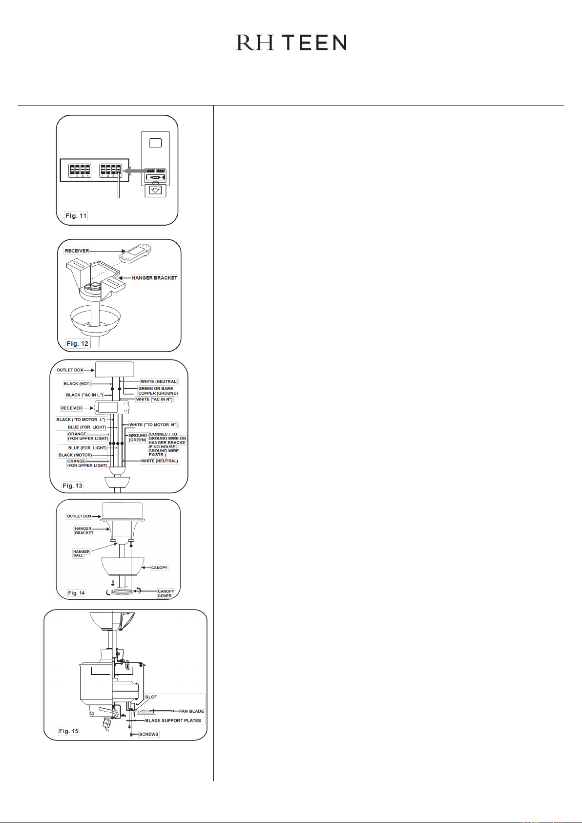
TO REDUCE THE RISK OF FIRE OR ELECTRONIC SHOCK, THIS FAN ONLY
CAN USE CFR-3T SOLID-STATE SPEED CONTROL WITH TR111A WALL
CONTROL ONLY.
INSTALLING THE FAN
Tools Required: Phillips screw driver; slotted screw driver; step-ladder; wire cutters;
electrical tape.
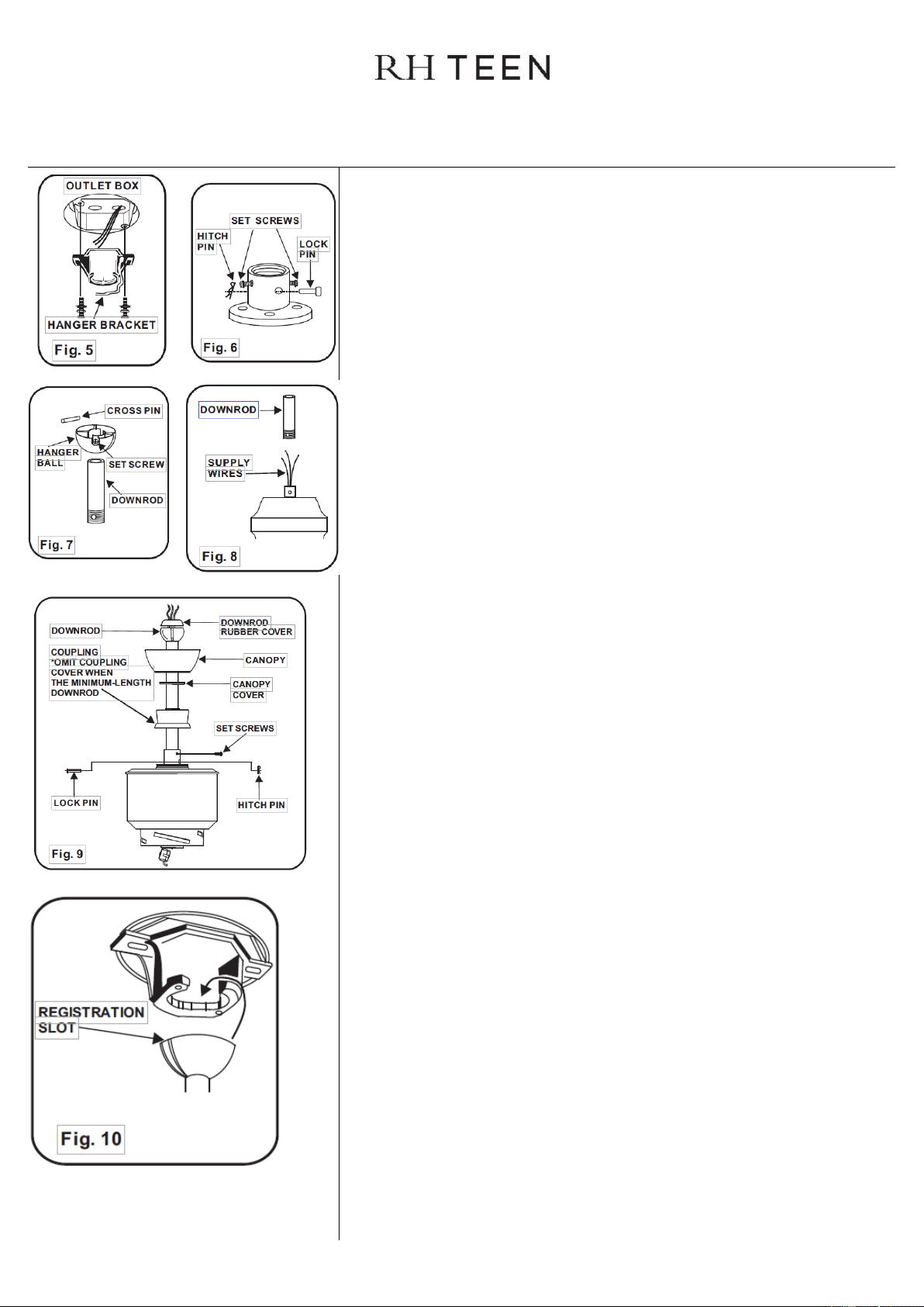
MOUNTING OPTIONS
If there isn't an existing mounting box, then read the following instructions.
Disconnect the power by removing fuses or turning off circuit breakers.
Secure the outlet box directly to the building structure. Use appropriate fasteners and
building materials. The outlet box and its support must be able to fully support the
moving weight of the fan (at least 50 lbs.). Use a UL Listed metal outlet box. Do not
use a plastic outlet box.
PARTS ENCLOSED
Fan blades (4)
Blade support plates (4 )
Hanger bracket
Canopy
Canopy cover
Standard downrod assembly
Minimum-length downrod
Coupling cover
Fan motor/housing assembly
Mounting plate
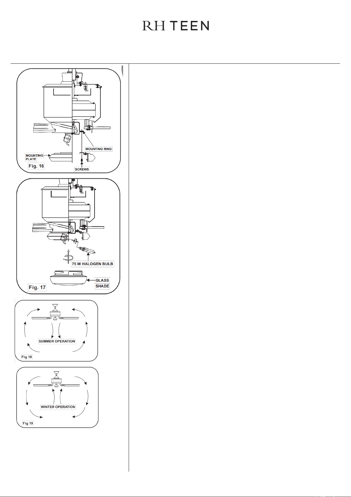
Glass Shade
Metal light cover
Receiver with 6 wire nuts
Transmitter+holder+2
mounting screws
Balancing kit
75W halogen bulb
12V MN21/A23 battery
#10 x 1.5" Wood screws (2
PCs.) #8 x 3/4" Machine
screws (2 pc.) Lock
washers (2 pcs.)
4mm Star washers (2 pcs.)
Wire nuts (3 pcs. )
Washers (2 pcs.)
3/16" x 15 mm Screws
with lock washers (13
pcs.)
Downrod Rubber Cover