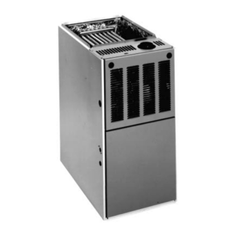
manuals.online logo
Brands
  1. Home
  2. •
  3. Brands
  4. •
  5. Rheem
  6. •
  7. Furnace
  8. •
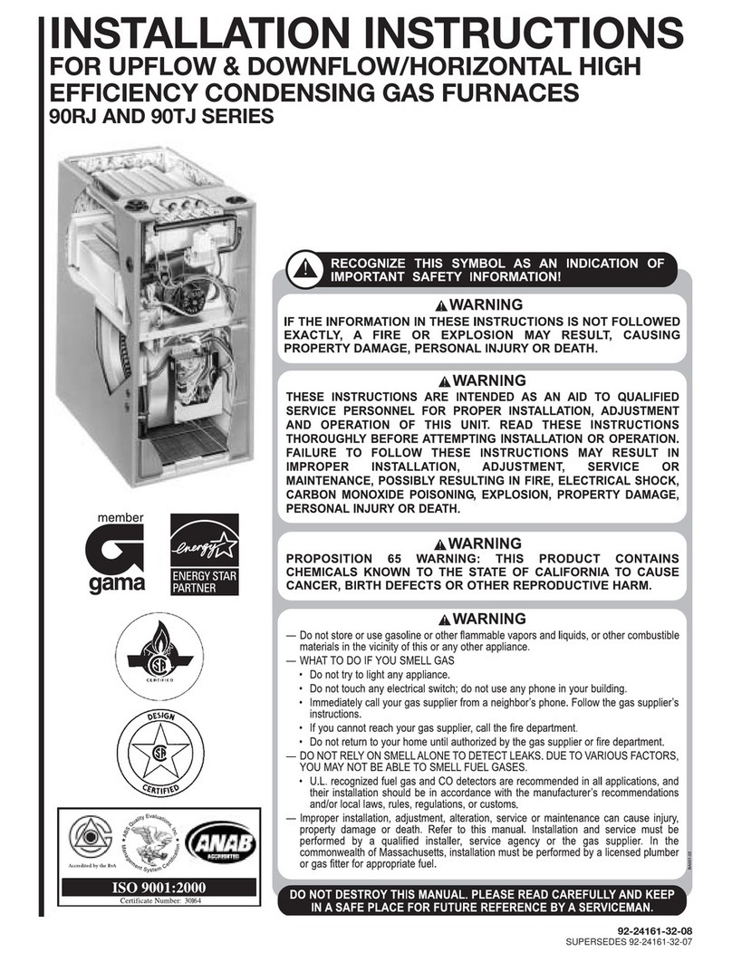
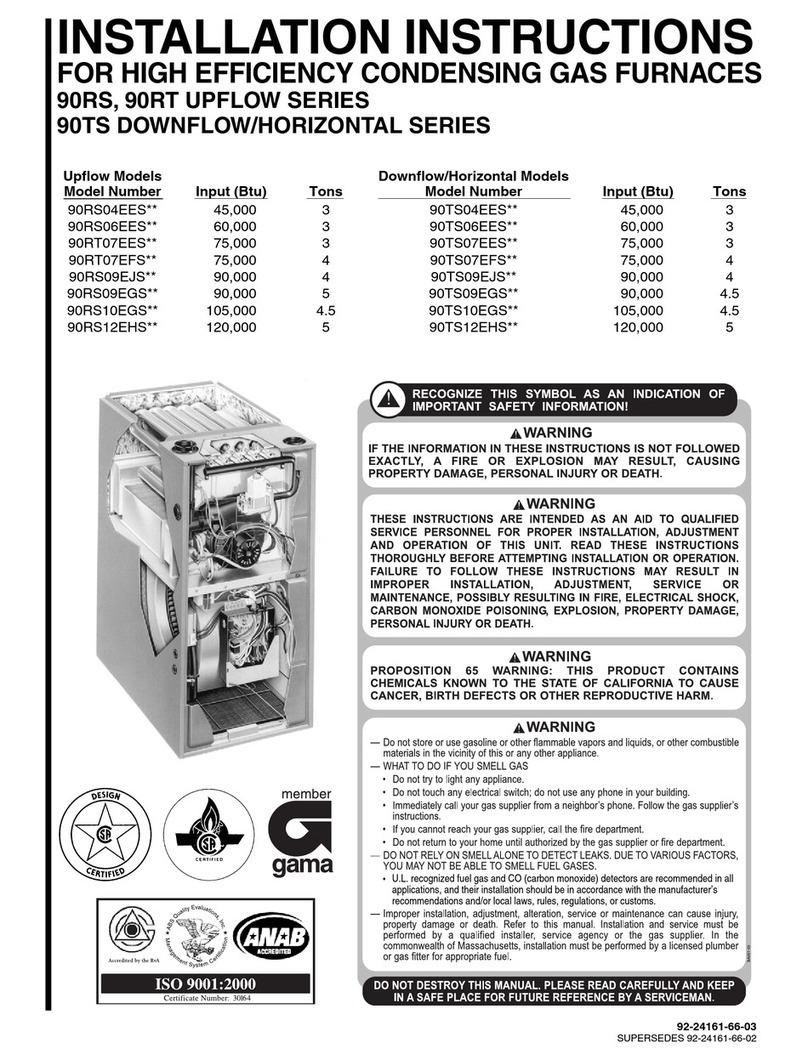
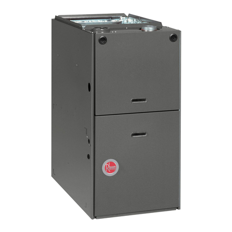
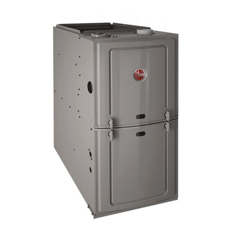
  9. Rheem GF801U UPFLOW Series User manual

Rheem GF801U UPFLOW Series User manual

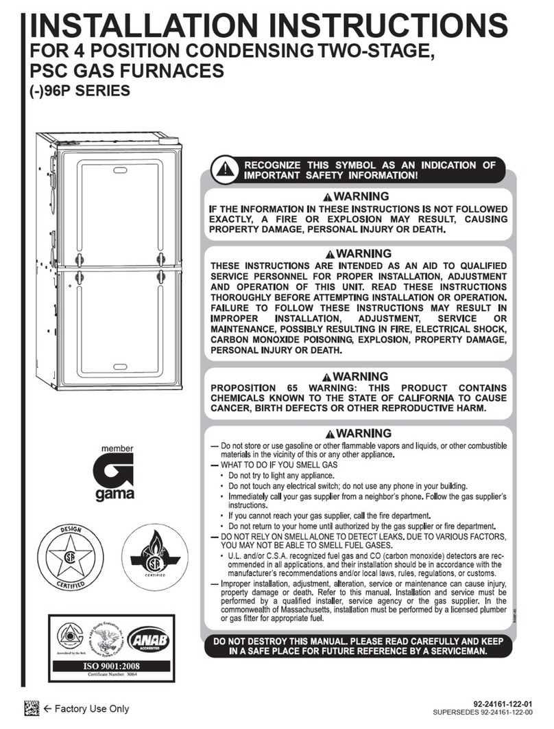
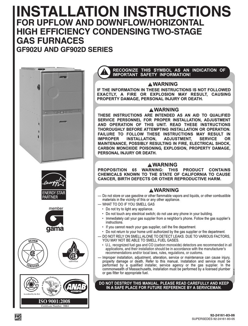
92-24161-80-01
SUPERSEDES 92-24161-80-00
INSTALLATION INSTRUCTIONS
FOR INDUC D DRAFT GAS FURNAC S
GF801U UPFLOW/HORIZONTAL S RI S
GF801D DOWNFLOW S RI S
ISO 9001:2008
U.L. r cogniz d fu l gas and CO (carbon monoxid ) d t ctors ar r comm nd d in
all applications, and th ir installation should b in accordanc with th
manufactur r’s r comm ndations and/or local laws, rul s, r gulations, or customs.
Upflow Models Downflow Models
Model Number Input (Btu) Tons Model Number Input (Btu) Tons
GF801U050AS36 50,000 3 GF801D050AS36 50,000 3
GF801U075AS48 75,000 4 GF801D075AS36 75,000 3
GF801U100AW48 100,000 4 GF801D100AW48 100,000 4
GF801U125AS60 125,000 5 GF801D125AS60 125,000 5
2
Before beginning any troubleshooting procedure, complete the following installation checklist. A furnace malfunction is
sometimes caused by an improper installation. By completing this checklist, the problem may be found and corrected. Make
copies of the checklist and complete one for every Low Profile Furnace service call for your records.
INSTALLATION CHECKLIST
(Refer to this manual for specifics.)
GAS SUPPLY
Adequate pipe size
No gas leaks
Proper supply and manifold gas pressure (check with an accurate U-tube manometer with the furnace and all other gas
appliances operating.)
L CTRICAL
orrect thermostat and subbase Thermostat model Subbase model
orrect thermostat mode and setting
orrect line supply voltage
orrect power supply polarity is required with electronic ignition
orrect furnace ground to electrical panel
D microamp (µA) flame signal (hot surface ignition units)
orrect control voltage
Measure and set heat anticipator amperage
Air conditioning low voltage wires connected to terminals “Y” “ ” - not with wire nuts
V NTING
orrect vent pipe diameter and length (according to SA tables) Vent connection size
orrect venting material (according to SA tables)
orrect lining for masonry chimneys
Adequate clearance from combustibles
Proper negative pressure reading in the vent
Vent pipe secured to induced draft blower housing
COMBUSTION AIR
Proper source of combustion air
orrect combustion air opening size
Optional attic combustion air pull
Non-attic combustion air pull
FURNAC INSTALLATION
Adequate clearance from combustibles
Adequate clearance for service
Proper air temperature rise (See furnace rating plate)
External static pressure inches w.c.
orrect filter(s)
orrect cooling coil or accessories (if equipped)
Adequate supply and return air ducting Return Air Duct Size Supply Air Duct Size
Air ducts sealed to prevent leakage
33
IMPORTANT: TO INSURE PROPER INSTALLATION AND OPERATION OF
THIS PRODUCT, CO PLETELY READ ALL INSTRUCTIONS PRIOR TO
ATTE PTING TO ASSE BLE, INSTALL, OPERATE, AINTAIN OR REPAIR
THIS PRODUCT. UPON UNPACKING OF THE FURNACE, INSPECT ALL
PARTS FOR DA AGE PRIOR TO INSTALLATION AND START-UP.
CONTENTS
Installation heck List ............................................................................................2
Safety Information..................................................................................................4
General Information ...............................................................................................8
Location Requirements and onsiderations ..........................................................9
ombustion and Ventilation Air............................................................................14
Vent Pipe Installation ...........................................................................................18
Gas Supply and Piping ........................................................................................21
Electrical Wiring ...................................................................................................25
Thermostat...........................................................................................................25
Accessories..........................................................................................................26
Furnace Twinning ................................................................................................26
High Altitude Installations.....................................................................................27
Start-Up Procedure ..............................................................................................30
Air Flow ................................................................................................................32
Blower Performance Data....................................................................................33
Safety Features....................................................................................................34
Maintenance ........................................................................................................35
Troubleshooting ...................................................................................................38
Wiring Diagram ....................................................................................................39
Important: All manufacturer products
meet current Federal OSHA Guidelines
for safety. alifornia Proposition 65
warnings are required for certain
products, which are not covered by the
OSHA standards.
alifornia's Proposition 65 requires
warnings for products sold in alifornia
that contain, or produce, any of over
600 listed chemicals known to the State
of alifornia to cause cancer or birth
defects such as fiberglass insulation,
lead in brass, and combustion products
from natural gas.
All “new equipment” shipped for sale in
alifornia will have labels stating that
the product contains and/or produces
Proposition 65 chemicals. Although we
have not changed our processes,
having the same label on all our
products facilitates manufacturing and
shipping. We cannot always know
“when, or if” products will be sold in the
alifornia market.
You may receive inquiries from
customers about chemicals found in, or
produced by, some of our heating and
air-conditioning equipment, or found in
natural gas used with some of our
products. Listed below are those
chemicals and substances commonly
associated with similar equipment in
our industry and other manufacturers.
• Glass Wool (Fiberglass) Insulation
• arbon Monoxide ( O)
• Formaldehyde
• Benzene
More details are available at the
Websites for OSHA (Occupational
Safety and Health Administration), at
www.osha.gov and the State of
alifornia's OEHHA (Office of
Environmental Health Hazard
Assessment), at www.oehha.org.
onsumer education is important since
the chemicals and substances on the
list are found in our daily lives. Most
consumers are aware that products
present safety and health risks, when
improperly used, handled and
maintained.
4
N V R T ST FOR GAS L AKS
WITH AN OP N FLAM . US A
COMM RCIALLY AVAILABL
SOAP SOLUTION MAD
SP CIFICALLY FOR TH
D T CTION OF L AKS TO CH CK
ALL CONN CTIONS, AS
SP CIFI D IN GAS SUPPLY AND
PIPING S CTION OF TH S
INSTRUCTIONS.
TH MANUFACTUR R IS NOT
R SPONSIBL FOR QUIPM NT
THAT IS MISMATCH D OR
IMPROP RLY INSTALL D.
COMBUSTION PRODUCTS MUST
B DISCHARG D OUTDOORS.
CONN CT THIS FURNAC TO AN
APPROV D V NT SYST M ONLY,
AS SP CIFI D IN V NT PIP
INSTALLATION S CTION OF
TH S INSTRUCTIONS.
PROVID AD QUAT
COMBUSTION AND V NTILATION
AIR TO TH FURNAC SPAC AS
SP CIFI D IN TH V NTING
S CTION OF TH S
INSTRUCTIONS.
INSTALL THIS FURNAC ONLY IN
A LOCATION AND POSITION AS
SP CIFI D IN TH LOCATION
R QUIR M NTS AND
CONSID RATIONS S CTION OF
TH S INSTRUCTIONS.
US ONLY WITH TYP OF GAS
APPROV D FOR THIS FURNAC .
R F R TO TH FURNAC RATING
PLAT .
WH N A FURNAC IS INSTALL D
SO THAT SUPPLY DUCTS CARRY
AIR CIRCULAT D BY TH
FURNAC TO AR AS OUTSID
TH SPAC CONTAINING TH
FURNAC , TH R TURN AIR
SHALL ALSO B HANDL D BY
DUCT(S) S AL D TO TH
FURNAC CASING AND
T RMINATING OUTSID TH
SPAC CONTAINING TH
FURNAC .
ALWAYS INSTALL FURNAC TO
OP RAT WITHIN TH
FURNAC 'S INT ND D
T MP RATUR -RIS RANG
WITH A DUCT SYST M WHICH
HAS AN XT RNAL STATIC
PR SSUR WITHIN TH
ALLOWABL RANG , AS
SP CIFI D IN DUCTING S CTION
OF TH S INSTRUCTIONS. S
ALSO FURNAC RATING
!WARNING
IF TH INFORMATION IN TH S
INSTRUCTIONS IS NOT
FOLLOW D XACTLY, A FIR OR
XPLOSION MAY R SULT,
CAUSING PROP RTY DAMAG ,
P RSONAL INJURY OR D ATH.
!WARNING
TH S INSTRUCTIONS AR
INT ND D AS AN AID TO
QUALIFI D S RVIC P RSONN L
FOR PROP R INSTALLATION,
ADJUSTM NT AND OP RATION
OF THIS UNIT. R AD TH S
INSTRUCTIONS THOROUGHLY
B FOR ATT MPTING
INSTALLATION OR OP RATION.
FAILUR TO FOLLOW TH S
INSTRUCTIONS MAY R SULT IN
IMPROP R INSTALLATION,
ADJUSTM NT, S RVIC OR
MAINT NANC , POSSIBLY
R SULTING IN FIR , L CTRICAL
SHOCK, CARBON MONOXID
POISONING, XPLOSION,
PROP RTY DAMAG , P RSONAL
INJURY OR D ATH.
!WARNING
—Do not stor or us gasolin or oth r
flammabl vapors and liquids, or
oth r combustibl mat rials in th
vicinity of this or any oth r applianc .
— WHAT TO DO IF YOU SMELL GAS
• Do not try to light any applianc .
• Do not touch any l ctrical switch;
do not us any phon in your
building.
• Imm diat ly call your gas suppli r
from a n ighbor’s phon . Follow th
gas suppli r’s instructions.
• If you cannot r ach your gas
suppli r, call th fir d partm nt.
• Do not r turn to your hom until
authoriz d by th gas suppli r or fir
d partm nt.
—DO NOT RELY ON SMELL ALONE TO
DETECT LEAKS. DUE TO VARIOUS
FACTORS, YOU MAY NOT BE ABLE
TO SMELL FUEL GASES.
• U.L. r cogniz d fu l gas and CO
(carbon monoxid ) d t ctors ar
r comm nd d in all applications,
and th ir installation should b in
accordanc with th manufactur r’s
r comm ndations and/or local laws,
rul s, r gulations, or customs.
— Improp r installation, adjustm nt,
alt ration, s rvic or maint nanc can
caus injury, prop rty damag or
d ath. R f r to this manual.
Installation and s rvic must b
p rform d by a qualifi d install r,
s rvic ag ncy or th gas suppli r. In
th commonw alth of Massachus tts,
installation must b p rform d by a
lic ns d plumb r or gas fitt r for
appropriat fu l.
!WARNING
!WARNING
!WARNING
!WARNING
!WARNING
PROPOSITION 65 WARNING: THIS
PRODUCT CONTAINS CH MICALS
KNOWN TO TH STAT OF
CALIFORNIA TO CAUS CANC R,
BIRTH D F CTS OR OTH R
R PRODUCTIV HARM.
!WARNING !WARNING
!WARNING
!WARNING
SAFETY INFORMATION
5
WH N THIS FURNAC IS
INSTALL D IN A R SID NTIAL
GARAG , IT MUST B INSTALL D
SO TH BURN RS AND IGNITION
SOURC AR LOCAT D NO L SS
THAN 18 INCH S ABOV TH
FLOOR. THIS IS TO R DUC TH
RISK OF IGNITING FLAMMABL
VAPORS WHICH MAY
B PR S NT IN A GARAG .
ALSO, TH FURNAC MUST B
LOCAT D OR PROT CT D TO
AVOID PHYSICAL DAMAG BY
V HICL S. FAILUR TO FOLLOW
TH S WARNINGS CAN CAUS A
FIR OR XPLOSION, R SULTING
IN PROP RTY DAMAG ,
P RSONAL INJURY OR D ATH.
US OF THIS FURNAC IS
ALLOW D DURING
CONSTRUCTION IF TH
FOLLOWING T MPORARY
INSTALLATION R QUIR M NTS
AR M T. INSTALLATION MUST
COMPLY WITH ALL
INSTALLATION INSTRUCTIONS
INCLUDING:
• PROP R V NT INSTALLATION;
• FURNAC OP RATING UND R
TH RMOSTATIC CONTROL;
• R TURN AIR DUCT S AL D TO
TH FURNAC ;
• AIR FILT RS IN PLAC ;
• S T FURNAC INPUT RAT
AND T MP RATUR RIS P R
RATING PLAT MARKING;
• M ANS FOR PROVIDING
OUTDOOR AIR R QUIR D FOR
COMBUSTION;
• R TURN AIR T MP RATUR
MAINTAIN D B TW N 55°F
(13°C) AND 80°F (27°C); AND
• CL AN FURNAC , DUCT WORK
AND COMPON NTS UPON
SUBSTANTIAL COMPL TION OF
TH CONSTRUCTION
PROC SS, AND V RIFY
FURNAC OP RATING
CONDITIONS INCLUDING
IGNITION, INPUT RAT ,
T MP RATUR RIS AND
V NTING, ACCORDING TO TH
INSTRUCTIONS.
!WARNING
!WARNING
DUCT L AKS CAN CR AT AN
UNBALANC D SYST M AND DRAW
POLLUTANTS SUCH AS DIRT,
DUST, FUM S AND ODORS INTO
TH HOM CAUSING PROP RTY
DAMAG . FUM S AND ODORS
FROM TOXIC, VOLATIL OR
FLAMMABL CH MICALS, AS W LL
AS AUTOMOBIL XHAUST AND
CARBON MONOXID (CO), CAN B
DRAWN INTO TH LIVING SPAC
THROUGH L AKING DUCTS AND
UNBALANC D DUCT SYST MS
CAUSING P RSONAL INJURY OR
D ATH (S FIGUR 1).
• IF AIR-MOVING QUIPM NT OR
DUCTWORK IS LOCAT D IN
GARAG S OR OFF-GARAG
STORAG AR AS - ALL JOINTS,
S AMS, AND OP NINGS IN TH
QUIPM NT AND DUCT MUST B
S AL D TO LIMIT TH
MIGRATION OF TOXIC FUM S
AND ODORS INCLUDING CARBON
MONOXID FROM MIGRATING
INTO TH LIVING SPAC .
• IF AIR-MOVING QUIPM NT OR
DUCTWORK IS LOCAT D IN
SPAC S CONTAINING FU L
BURNING APPLIANC S SUCH AS
WAT R H AT RS OR BOIL RS -
ALL JOINTS, S AMS, AND
OP NINGS IN TH QUIPM NT
AND DUCT MUST ALSO B
S AL D TO PR V NT
D PR SSURIZATION OF TH
SPAC AND POSSIBL
MIGRATION OF COMBUSTION
BYPRODUCTS INCLUDING
CARBON MONOXID INTO TH
LIVING SPAC .
UPFLOW AND HORIZONTAL
FURNAC S MUST NOT B
INSTALL D DIR CTLY ON
CARP TING, TIL OR OTH R
COMBUSTIBL MAT RIAL OTH R
THAN WOOD FLOORING.
INSTALLATION ON A
COMBUSTIBL MAT RIAL CAN
R SULT IN FIR CAUSING
PROP RTY DAMAG , S V R
P RSONAL INJURY OR D ATH.
!WARNING
!WARNING
DOWNFLOW UNIT D SIGN IS
C RTIFI D FOR INSTALLATION ON
NON-COMBUSTIBL FLOOR. A
SP CIAL COMBUSTIBL FLOOR
SUB-BAS IS R QUIR D WH N
INSTALLING ON A COMBUSTIBL
FLOOR. FAILUR TO INSTALL TH
SUB-BAS MAY R SULT IN FIR ,
PROP RTY DAMAG , P RSONAL
INJURY OR D ATH. THIS SP CIAL
BAS IS OFF R D AS AN
ACC SSORY FROM TH FACTORY.
S TH CL ARANC LAB L
LOCAT D INSID TH FURNAC
FOR TH APPROPRIAT MOD L
NUMB R.
TH SP CIAL BAS IS NOT
R QUIR D WH N TH FURNAC IS
INSTALL D ON TOP OF AN AIR
CONDITIONING PL NUM.
!WARNING
WH N COILS AR US D WITH AIR
HANDL RS OR FURNAC S AND
INSTALL D ABOV A FINISH D
C ILING OR LIVING AR A, IT IS
R COMM ND D THAT AN
AUXILIARY SH T M TAL
COND NSAT DRAIN PAN B
FABRICAT D AND INSTALL D
UND R NTIR UNIT. FAILUR TO
DO SO CAN R SULT IN PROP RTY
DAMAG . RUN COND NSAT TO A
LOCATION WH R IT IS
NOTIC ABL .
!CAUTION
THIS FURNAC IS NOT APPROV D
FOR INSTALLATION IN A MOBIL
HOM . DO NOT INSTALL THIS
FURNAC IN A MOBIL HOM .
INSTALLATION IN A MOBIL HOM
COULD CAUS FIR , PROP RTY
DAMAG , P RSONAL INJURY OR
D ATH.
!WARNING
COMBUSTIBL MAT RIAL MUST
NOT B PLAC D ON OR AGAINST
TH FURNAC JACK T OR WITHIN
TH SP CIFI D CL ARANC S OF
TH V NT PIP . TH AR A
AROUND TH FURNAC MUST B
K PT CL AR AND FR OF ALL
COMBUSTIBL MAT RIALS
INCLUDING GASOLIN AND OTH R
FLAMMABL VAPORS AND
LIQUIDS. PLAC M NT OF
COMBUSTIBL MAT RIALS ON,
AGAINST OR AROUND TH
FURNAC JACK T CAN CAUS AN
XPLOSION OR FIR R SULTING IN
PROP RTY DAMAG , P RSONAL
INJURY OR D ATH. TH FURNAC
OWN R SHOULD B CAUTION D
THAT TH FURNAC AR A MUST
NOT B US D AS A BROOM
CLOS T OR FOR ANY OTH R
STORAG PURPOS S.
!WARNING
6
COMBUSTION AIR INTAK S
CANNOT B T RMINAT D OUTSID .
DOING SO CAN CAUS IMPROP R
OP RATION OF TH FURNAC .
!CAUTION
US OF SH T M TAL AIR INTAK
PIP INST AD OF PVC MAY R SULT
IN NOIS ISSU S.
!CAUTION
D VIC S ATTACH D TO TH FLU
OR V NT FOR TH PURPOS OF
R DUCING H AT LOSS UP TH
CHIMN Y HAV NOT B N T ST D
AND HAV NOT B N INCLUD D IN
TH D SIGN C RTIFICATION OF
THIS FURNAC . W , TH
MANUFACTUR R, CANNOT AND
WILL NOT B R SPONSIBL FOR
INJURY OR DAMAG CAUS D BY
TH US OF SUCH UNT ST D
AND/OR UNC RTIFI D D VIC S,
ACC SSORI S OR COMPON NTS.
!WARNING
V NT PIP ATTACHING HOL S
MUST B PR DRILL D IN TH
DRAFT INDUC R COLLAR TO
PR V NT DAMAGING TH
INDUC R. DRILL 1/8” DIAM T R
HOL S THROUGH TH V NT PIP
AND COLLAR AND US #8 SCR WS
TO ATTACH. S FIGUR 12.
FAILUR TO FOLLOW THIS
WARNING CAN CAUS
R CIRCULATION OF FLU
PRODUCTS CAUSING CARBON
MONOXID POISONING R SULTING
IN P RSONAL INJURY OR D ATH.
!WARNING
TH DOWNFLOW FURNAC
D SIGN IS C RTIFI D FOR
INSTALLATION ON A NON-
COMBUSTIBL FLOOR. IF
INSTALL D ON A COMBUSTIBL
FLOOR, US TH SP CIAL BAS
SP CIFI D ON TH FURNAC
CL ARANC LAB L. FAILUR TO
INSTALL TH SP CIAL BAS MAY
R SULT IN FIR , PROP RTY
DAMAG , P RSONAL INJURY OR
D ATH. THIS SP CIAL BAS IS
SHIPP D FROM TH FACTORY AS
AN ACC SSORY.
!WARNING
THIS FURNAC AND ANY OTH R
FU L-BURNING APPLIANC MUST
B PROVID D WITH NOUGH
FR SH AIR FOR PROP R
COMBUSTION AND V NTILATION
OF TH FLU GAS S. MOST
HOM S WILL R QUIR THAT
OUTSID AIR B SUPPLI D INTO
TH FURNAC AR A. FAILUR TO
DO SO CAN CAUS D ATH FROM
CARBON MONOXID POISONING.
!WARNING
ALL FURNAC INSTALLATIONS
MUST COMPLY WITH TH
NATIONAL FU L GAS COD AND
LOCAL COD S TO PROVID
AD QUAT COMBUSTION AND
V NTILATION AIR FOR TH
FURNAC . FAILUR TO DO SO CAN
CR AT HAZARDOUS CONDITIONS
R SULTING IN PROP RTY
DAMAG , BODILY INJURY OR
D ATH FROM SMOK , FIR OR
CARBON MONOXID .
!WARNING
NV R ALLOW PRODUCTS OF
COMBUSTION OR TH FLU
PRODUCTS TO NT R TH
RTURN AIR DUCTWORK, OR TH
CIRCULATING AIR SUPPLY. ALL
RTURN DUCTWORK MUST B
AD QUAT LY S AL D AND
SCUR D TO TH FURNAC WITH
SH T M TAL SCR WS, AND
JOINTS TAP D. WH N A FURNAC
IS MOUNT D ON A PLATFORM,
WITH R TURN THROUGH TH
BOTTOM, IT MUST B S AL D
AIRTIGHT B TW N TH FURNAC
AND TH R TURN AIR PL NUM.
TH R TURN AIR PL NUM MUST
B P RMAN NTLY NCLOS D.
N V R US A DOOR AS A PART OF
TH R TURN AIR PL NUM. TH
FLOOR OR PLATFORM MUST
PROVID SOUND PHYSICAL
SUPPORT OF TH FURNAC ,
WITHOUT SAGGING, CRACKS,
GAPS, TC., AROUND TH BAS AS
TO PROVID A S AL B TW N
TH SUPPORT AND TH BAS .
FAILUR TO PR V NT PRODUCTS
OF COMBUSTION FROM B ING
CIRCULAT D INTO TH LIVING
SPAC CAN CR AT POT NTIALLY
HAZARDOUS CONDITIONS,
INCLUDING CARBON MONOXID
POISONING THAT COULD R SULT
IN P RSONAL INJURY OR D ATH.
DO NOT, UND R ANY
CIRCUMSTANC S, CONN CT
R TURN OR SUPPLY DUCTWORK
TO OR FROM ANY OTH R H AT
PRODUCING D VIC SUCH AS A
FIR PLAC INS RT, STOV , TC.
DOING SO MAY R SULT IN FIR ,
CARBON MONOXID POISONING,
XPLOSION, P RSONAL INJURY
OR PROP RTY DAMAG .
!WARNING
BLOW R AND BURN RS MUST
N V R B OP RAT D WITHOUT
TH BLOW R DOOR IN PLAC .
THIS IS TO PR V NT DRAWING
GAS FUM S (WHICH COULD
CONTAIN HAZARDOUS CARBON
MONOXID ) INTO TH HOM THAT
COULD R SULT IN P RSONAL
INJURY OR D ATH.
!WARNING
A SOLID M TAL BAS PLAT , (S
TABL 1) MUST B IN PLAC
WH N TH FURNAC IS
INSTALL D WITH SID AIR
R TURN DUCTS. FAILUR TO
INSTALL A BAS PLAT COULD
CAUS PRODUCTS OF
COMBUSTION TO B CIRCULAT D
INTO TH LIVING SPAC AND
CR AT POT NTIALLY
HAZARDOUS CONDITIONS,
INCLUDING CARBON MONOXID
POISONING OR D ATH.
!WARNING
7
N V R PURG A GAS LIN INTO
TH COMBUSTION CHAMB R.
N V R US MATCH S, FLAM OR
ANY IGNITION SOURC FOR
CH CKING L AKAG . FAILUR TO
FOLLOW THIS WARNING CAN
CAUS AN XPLOSION OR FIR
R SULTING IN PROP RTY
DAMAG , P RSONAL INJURY OR
D ATH.
!WARNING
TURN OFF L CTRIC POW R AT
TH FUS BOX OR S RVIC PAN L
B FOR MAKING ANY L CTRICAL
CONN CTIONS.
ALSO, TH GROUND CONN CTION
MUST B COMPL T D B FOR
MAKING LIN VOLTAG
CONN CTIONS. FAILUR TO DO SO
CAN R SULT IN L CTRICAL
SHOCK, S V R P RSONAL
INJURY OR D ATH.
!WARNING
TH CABIN T MUST B
PRMAN NTLY GROUND D. A
GROUND SCR W IS PROVID D IN
TH JUNCTION BOX FOR THIS
PURPOS . FAILUR TO DO SO CAN
RSULT IN FIR , L CTRICAL
SHOCK, P RSONAL INJURY OR
DATH.
!WARNING
DO NOT CONN CT THIS FURNAC
TO A CHIMN Y US D TO V NT A
SOLID FU L APPLIANC (WOOD OR
COAL). V NTING WITH A SOLID
FU L APPLIANC CAN L AD TO
IMPROP R FUNCTIONING OF TH
UNIT, AND DU TO SOOTING, TH
POSSIBILITY OF FIR R SULTING IN
PROP RTY DAMAG , P RSONAL
INJURY OR D ATH.
!WARNING
THIS FURNAC IS QUIPP D AT TH
FACTORY FOR US ON NATURAL
GAS ONLY. CONV RSION TO LP
GAS R QUIR S A SP CIAL KIT
AVAILABL FROM TH
DISTRIBUTOR. FAILUR TO US TH
PROP R CONV RSION KIT CAN
CAUS FIR , CARBON MONOXID
POISONING, XPLOSION,
PROP RTY DAMAG , P RSONAL
INJURY OR D ATH.
!WARNING
L VATIONS ABOV 2000 FT
R QUIR THAT TH FURNAC
INPUT RATING B ADJUST D AND
THAT TH SIZ OF TH BURN R
ORIFIC S B R -CALCULAT D
BAS D ON L VATION AND GAS
H ATING VALU . TH BURN R
ORIFIC S MAY (OR MAY NOT) N D
TO B CHANG D. S TH
S CTION TITL D “HIGH ALTITUD
INSTALLATIONS” OF THIS BOOK
FOR INSTRUCTIONS.
!CAUTION
DISCONN CT TH L CTRICAL
SUPPLY TO TH FURNAC B FOR
ATT MPTING TO CHANG TH
BLOW R SP D. FAILUR TO DO
SO CAN CAUS L CTRICAL
SHOCK R SULTING IN S V R
P RSONAL INJURY OR D ATH.
!CAUTION
IT IS IMPORTANT THAT ACH DUCT
SYST M B SIZ D AND INSTALL D
FOR TH SP CIFIC APPLICATION BY
PROP RLY APPLYING TH
APPROPRIAT INDUSTRY
ACC PT D STANDARD. IF L SS
THAN MINIMUM STANDARDS AR
APPLI D, TH QUIPM NT US R
COULD XP CT TO XP RI NC
HIGH R UTILITY BILLS, MAJOR
COMPON NT FAILUR , VARYING
D GR S OF AIR NOIS OR OTH R
UNSATISFACTORY ISSU S, OV R
WHICH TH MANUFACTUR R HAS
NO CONTROL.
!CAUTION
DISCONN CT MAIN L CTRICAL
POW R TO TH UNIT B FOR
ATT MPTING ANY MAINT NANC .
FAILUR TO DO SO CAN CAUS
L CTRICAL SHOCK R SULTING IN
S V R P RSONAL INJURY OR
D ATH.
!WARNING
COMBUSTIBL MAT RIAL MUST
NOT B PLAC D ON OR AGAINST
TH FURNAC JACK T OR WITHIN
TH SP CIFI D CL ARANC S OF
TH V NT PIP . TH AR A AROUND
TH FURNAC MUST B K PT
CL AR AND FR OF ALL
COMBUSTIBL MAT RIALS
INCLUDING GASOLIN AND OTH R
FLAMMABL VAPORS AND
LIQUIDS. PLAC M NT OF
COMBUSTIBL MAT RIALS ON,
AGAINST OR AROUND TH
FURNAC JACK T CAN CAUS AN
XPLOSION OR FIR R SULTING IN
PROP RTY DAMAG , P RSONAL
INJURY OR D ATH. TH FURNAC
OWN R SHOULD B CAUTION D
THAT TH FURNAC AR A MUST
NOT B US D AS A BROOM
CLOS T OR FOR ANY OTH R
STORAG PURPOS S.
!WARNING
INSTALLATION OF THIS FURNAC
AT ALTITUD S ABOV 2000 FT (610
m) SHALL B IN ACCORDANC
WITH LOCAL COD S, OR IN TH
ABS NC OF LOCAL COD S, TH
NATIONAL FU L GAS COD , ANSI
Z223.1/NFPA 54 OR NATIONAL
STANDARD OF CANADA, NATURAL
GAS AND PROPAN INSTALLATION
COD , CAN B149.1.
!CAUTION
B SUR THAT TH MANUAL GAS
VALV HAS B N IN TH “OFF”
POSITION FOR AT L AST FIV
MINUT S. DO NOT ATT MPT TO
MANUALLY LIGHT TH MAIN
BURN RS. FAILUR TO FOLLOW
THIS WARNING CAN CAUS A FIR
OR AN XPLOSION R SULTING IN
PROP RTY DAMAG , P RSONAL
INJURY OR D ATH.
!WARNING
SHOULD OV RH ATING OCCUR OR
TH GAS SUPPLY FAIL TO SHUT
OFF, SHUT OFF TH MANUAL GAS
VALV TO TH APPLIANC B FOR
SHUTTING OFF TH L CTRICAL
SUPPLY. FAILUR TO DO SO CAN
CAUS AN XPLOSION OR FIR
R SULTING IN PROP RTY DAMAG ,
P RSONAL INJURY OR D ATH.
!WARNING
HOL S IN TH V NT PIP OR H AT
XCHANG R CAN CAUS TOXIC
FUM S TO NT R TH HOM
R SULTING IN CARBON MONOXID
POISONING OR D ATH. TH V NT
PIP OR H AT XCHANG R MUST
B R PLAC D IF TH Y L AK.
!WARNING
8
The 80% gas furnaces are design
certified by SA for use with natural and
propane gases as follows:
As a ategory I furnace, it may be
vented vertically with type B-1 vent
pipe and also may be common
vented as described in these
instructions.
This furnace should be installed in
accordance with the American National
Standard Z223.1 - latest edition booklet
entitled “National Fuel Gas ode”
(NFPA 54) (in anada, SA B149.1 and
.2 Installation odes for gas burning
appliances), and the requirements or
codes of the local utility or other
authority having jurisdiction including
local plumbing or waste water codes.
The National Appliance Energy
onservation Act (NAE A) of 1987
states that any gas furnace
manufactured after January 1, 1992,
must have a minimum Annual Fuel
Utilization Efficiency (AFUE) of 78%.
The higher the AFUE percentage the
more usable heat energy the consumer
gets for every dollar of fuel purchased.
This is similar to the EPA's minimum gas
mileage requirement for automobiles. It
gives the consumer a relatively easy
way to make direct efficiency
comparisons between different furnace
brands and styles.
A high AFUE value, which translates into
a low operating cost, is not the only
concern that consumers have. They also
want a furnace with a reasonable
installed cost. They want a furnace that
provides them with comfort – their main
concern. And they expect a furnace with
exceptional reliability and longevity.
Gas furnace manufacturers are always
striving to provide consumers with the
best furnace value. The Low Profile
Furnace addresses all those consumer
needs. It gives exceptional efficiency
with a low installation cost. It delivers the
comfort the customer wants along with
the reliability they expect.
The key to all these customer benefits is
the furnace's heat exchanger. The
materials used to construct the furnace
in general and the heat exchanger in
particular make it a rugged, long lasting
unit. The unique heat exchanger design
provides the customer with a furnace
only 34 inches high. This gives the
consumer a unit easily installed in
almost every location that accepts all
customary accessories.
With the introduction of higher efficiency
furnaces, special attention must be paid
to the venting system. Only listed
venting systems may be used as stated
in the installation instructions and the
National Fuel Gas Code, ANSI Z223.1
(NFPA 54), or the Canadian CAN/CGA
B149.1 and B149.2 Installation Codes
for Gas Burning Appliances. Since
furnace technology and venting
requirements are changing, awareness
of local, state, and federal codes and
industry changes is imperative.
GENERAL INFORMATION
IMPORTANT INFORMATION
ABOUT EFFICIENCY AND
INDOOR AIR QUALITY
entral cooling and heating equipment
is only as efficient as the duct system
that carries the cooled or heated air. To
maintain efficiency, comfort and good
indoor air quality, it is important to have
the proper balance between the air
being supplied to each room and the air
returning to the cooling and heating
equipment.
Proper balance and sealing of the duct
system improves the efficiency of the
heating and air conditioning system
and improves the indoor air quality of
the home by reducing the amount of
airborne pollutants that enter homes
from spaces where the ductwork and /
or equipment is located. The
manufacturer and the U.S.
Environmental Protection Agency’s
Energy Star Program recommend that
central duct systems be checked by a
qualified contractor for proper balance
and sealing.
DUCT L AKS CAN CR AT AN
UNBALANC D SYST M AND DRAW
POLLUTANTS SUCH AS DIRT,
DUST, FUM S AND ODORS INTO
TH HOM CAUSING PROP RTY
DAMAG . FUM S AND ODORS
FROM TOXIC, VOLATIL OR
FLAMMABL CH MICALS, AS W LL
AS AUTOMOBIL XHAUST AND
CARBON MONOXID (CO), CAN B
DRAWN INTO TH LIVING SPAC
THROUGH L AKING DUCTS AND
UNBALANC D DUCT SYST MS
CAUSING P RSONAL INJURY OR
D ATH (S FIGUR 1).
• IF AIR-MOVING QUIPM NT OR
DUCTWORK IS LOCAT D IN
GARAG S OR OFF-GARAG
STORAG AR AS - ALL JOINTS,
S AMS, AND OP NINGS IN TH
QUIPM NT AND DUCT MUST B
S AL D TO LIMIT TH
MIGRATION OF TOXIC FUM S
AND ODORS INCLUDING CARBON
MONOXID FROM MIGRATING
INTO TH LIVING SPAC .
FIGUR 1
MIGRATION OF DANG ROUS SUBSTANC S, FUM S, AND ODORS INTO LIVING SPAC S
NOT : Always perform a proper heat
loss calculation before specifying the
furnace size. This ensures that the
furnace is sized to adequately,
economically, heat the building and
provide the correct airflow for your
application.
IMPORTANT: PROPER APPLI ATION,
INSTALLATION AND MAINTENAN E
OF THIS FURNA E IS A MUST IF
ONSUMERS ARE TO RE EIVE THE
FULL BENEFITS FOR WHI H THEY
HAVE PAID.
Additional helpful publications available
from the “National Fire Protection
Association” are: NFPA-90A –
Installation of Air onditioning and
Ventilating Systems 1985 or latest
edition. NFPA-90B – Warm Air Heating
and Air onditioning Systems 1984.
These publications are available from:
National Fire Protection Association,
Inc.
Batterymarch Park
Quincy, MA 02269
SA-INTERNATIONAL
178 Rexdale Blvd.
Etobicoke (Toronto), Ontario
anada M9W, 1R3
WARNING
!
9
GENERAL INFORMATION
1. NOT : This furnace is shipped with
heat exchanger support brackets
installed under the back of the heat
exchanger. These may be removed
before installation, but it is not
required.
LOCATION
THIS FURNAC IS NOT APPROV D
FOR INSTALLATION IN A MOBIL
HOM . DO NOT INSTALL THIS
FURNAC IN A MOBIL HOM .
INSTALLATION IN A MOBIL HOM
COULD CAUS FIR , PROP RTY
DAMAG , P RSONAL INJURY OR
D ATH.
2. IMPORTANT: This furnace is not
approved or recommended for
installation on its back, with access
doors facing upwards.
3. This furnace is suitable for
installation in buildings constructed
on-site. This heating unit should be
centralized with respect to the heat
distribution system as much as
practicable.
4. NOT : These furnaces are
approved for installation in attics, as
well as alcoves, utility rooms,
closets and crawlspaces.
5. IMPORTANT: Support this unit when
installed. For attic or crawl space
installation, horizontal furnaces may
be installed on combustible wood
flooring or by using support brackets.
See Figure 2.
6. IMPORTANT: If installing in a utility
room, be sure the door is wide
enough to:
a. allow the largest part of the
furnace to pass; or
b. allow any other appliance (such
as a water heater) to pass.
LOCATION REQUIREMENTS AND CONSIDERATIONS
WARNING
!
FIGUR 2
HORIZONTAL FURNAC INSTALL D W/SUPPORT BRACK TS
ST-A0799-01
NOT : Do not block furnace
access with support rods. Maintain
clearances recommended in Figure 2.
Allow enough space for proper service
maintenance or replacement of the heat
exchanger and blower assembly.
EXHAUST
VENT
• IF AIR-MOVING QUIPM NT OR
DUCTWORK IS LOCAT D IN
SPAC S CONTAINING FU L
BURNING APPLIANC S SUCH AS
WAT R H AT RS OR BOIL RS -
ALL JOINTS, S AMS, AND
OP NINGS IN TH QUIPM NT
AND DUCT MUST ALSO B
S AL D TO PR V NT
D PR SSURIZATION OF TH
SPAC AND POSSIBL
MIGRATION OF COMBUSTION
BYPRODUCTS INCLUDING
CARBON MONOXID INTO TH
LIVING SPAC .
IMPROP R INSTALLATION, OR
INSTALLATION NOT MAD IN
ACCORDANC WITH TH
UND RWRIT RS LABORATORY
(UL) C RTIFICATION OR TH S
INSTRUCTIONS, CAN R SULT IN
UNSATISFACTORY OP RATION
AND/OR DANG ROUS CONDI-
TIONS AND AR NOT COV R D BY
TH UNIT WARRANTY.
IN COMPLIANC WITH
R COGNIZ D COD S, IT IS
R COMM ND D THAT AN
AUXILIARY DRAIN PAN B
INSTALL D UND R ALL
VAPORATOR COILS OR UNITS
CONTAINING VAPORATOR COILS
OR GAS FURNAC S US D WITH
VAPORATOR COILS THAT AR
LOCAT D IN ANY AR A OF A
STRUCTUR WH R DAMAG TO
TH BUILDING OR BUILDING
CONT NTS MAY OCCUR AS A
R SULT OF AN OV RFLOW OF TH
COIL DRAIN PAN OR A STOPPAG
IN TH PRIMARY COND NSAT
DRAIN PIPING.
RECEIVING
Immediately upon receipt, all cartons
and contents should be inspected for
transit damage. Units with damaged
cartons should be opened immediately.
If damage is found, it should be noted
on the delivery papers, and a damage
claim filed with the last carrier.
• After unit has been delivered to job
site, remove carton taking care not to
damage unit.
• heck the unit rating plate for unit
size, electric heat, coil, voltage,
phase, etc. to be sure equipment
matches what is required for the job
specification.
• Read the entire instructions before
starting the installation.
• Some building codes require extra
cabinet insulation and gasketing
when unit is installed in attic
applications.
• If installed in an unconditioned space,
apply caulking around the power
wires, control wires, refrigerant tubing
and condensate line where they enter
the cabinet. Seal the power wires on
the inside where they exit conduit
opening. aulking is required to
prevent air leakage into and
condensate from forming inside the
unit, control box, and on electrical
controls.
• Install the unit in such a way as to
allow necessary access to the
coil/filter rack and blower/control
compartment.
• Install the unit in a level position to
ensure proper condensate drainage.
Make sure unit is level in both
directions within 1/8”.
• Install the unit in accordance with
any local code which may apply and
the national codes. Latest editions
are available from: “National Fire
Protection Association, Inc.,
Batterysmarch Park, Quincy, MA
02269.” These publications are:
• ANSI/NFPA No. 70-(Latest Edition)
National Electrical ode.
• NFPA90A Installation of Air
onditioning and Ventilating
Systems.
• NFPA90B Installation of warm air
heating and air conditioning systems.
• The equipment has been evaluated
in accordance with the ode of
Federal Regulations, hapter XX,
Part 3280.
NOTIC
NOTIC
10
REDUCED CLEARANCE (IN.)
A B C D E F Left Right Back Top Front Vent Ship.
Side Side Wgts.
50 14 1227/32 105/8➀111/217/80 4➁0 1 3 6➂85 lbs.
75 171/21611/32 123/8➀15 21/20 3➁0 1 3 6➂105 lbs.
100 171/21611/32 123/8➀15 21/20 3➁0 1 3 6➂115 lbs.
100 21 1927/32 141/8➀181/221/20 0 0 1 3 6➂120 lbs.
125 241/22311/32 157/8➀22 21/20 0 0 1 3 6➂140 lbs.
150 241/22311/32 157/8➀22 21/20 0 0 1 3 6➂150 lbs.
CL ARANC TO COMBUSTIBL MAT RIAL (INCH S)
UPFLOW/HORIZONTAL MOD LS
TOP
L FT SID
FRONT
RIGHT SID
ALT RNAT
GAS CONN CTION
BOTTOM
R TURN
AIR
AIRFLOW
SUPPLY
AIR
2613/16
265/8
2411/32
2411/32
19/32
9/16
247/16
281/16
265/8
143/8
111/2
34
15/8DIA.
23
15
20
D
7/8DIA.
7/8DIA.
19/32
19/32
3/4
143/8
111/2
11/4
2317/32
F
GAS ONNE TION
ELE TRI AL ONNE TION
OPTIONAL RETURN AIR UTOUT
(EITHER SIDE) FOR USE WITH
EXTERNAL SIDE FILTER FRAME
LOW VOLTAGE
E
SIGHT
GLASS
A
B
FIGUR 3
UPFLOW/HORIZONTAL DIM NSIONS
IMPORTANT: This furnace is not approved or recommended for
installation on its back, with access doors facing upwards.
➀May r quir 3” to 4” or 3” or 5” adapt r.
➁May b 0” with typ B v nt.
➂May b 1” with typ B v nt.
241/2
25.406
Tons
3
3 & 4
3
4.5 & 5
5
5
Input-
kBtu
11
REDUCED CLEARANCE (IN.)
A B C D E Left Right Back Top Front Vent Ship.
Side Side Wgts.
50 14 1227/32 103/8➀13 1/80 4➁0 1 3 6➂85 lbs.
75 171/21611/32 121/8➀16 5/80 3➁0 1 3 6➂105 lbs.
100 171/21611/32 121/8➀16 5/80 3➁0 1 3 6➂115 lbs.
100 21 1927/32 137/8➀20 1/80 0 0 1 3 6➂120 lbs.
125 241/22311/32 155/8➀23 5/80 0 0 1 3 6➂140 lbs.
150 241/22311/32 155/8➀23 5/80 0 0 1 3 6➂150 lbs.
FIGUR 4
DOWNFLOW DIM NSIONS
TOP BOTTOM
241/2
193/4
A
BD
LOW VOLTAGE
GAS ONNE TION
ELE TRI ONNE TION
ES.A.
R.A.
265/8
2613/16
63/16
203/8
233/8
5/85/8
3/4
5/8
34
233/8
203/8
63/16
247/16
265/8
201/8
281/16
7/8DIA.
7/8DIA.
15/8DIA.
CL ARANC TO COMBUSTIBL MAT RIAL (INCH S)
DOWNFLOW MOD LS
NOT : IN DOWNFLOW ONFIGURATION, OPTIONAL AIR UTOUT IS NOT PERMITTED.
SIGHT
GLASS
AIRFLOW
➀May r quir 3” to 4” or 3” or 5” adapt r.
➁May b 0” with typ B v nt.
➂May b 1” with typ B v nt.
Tons
3
3 & 4
3
5 & 5.5
5
5
Input-
kBtu
12
CLEARANCE –
ACCESSIBILITY
The design of forced air furnaces with
input ratings as listed in the tables on
the following pages are certified by
SA for the clearances to combustible
materials shown in inches.
See name/rating plate and clearance
label for specific model number and
clearance information.
Service clearance of at least 24 inches
is recommended in front of all furnaces.
ACC SSIBILITY CL ARANC S,
WH R GR AT R, MUST TAK
PR C D NC OV R FIR
PROT CTION CL ARANC S.
UPFLOW AND HORIZONTAL
FURNAC S MUST NOT B
INSTALL D DIR CTLY ON
CARP TING, TIL OR OTH R
COMBUSTIBL MAT RIAL OTH R
THAN WOOD FLOORING.
INSTALLATION ON A
COMBUSTIBL MAT RIAL CAN
R SULT IN FIR CAUSING
PROP RTY DAMAG , S V R
P RSONAL INJURY OR D ATH.
A gas-fired furnace for installation in a
residential garage must be installed so
that the burner(s) and the ignition
source are located not less than 18”
above the floor and the furnace is
located or protected to avoid physical
damage by vehicles.
DOWNFLOW UNIT D SIGN IS
C RTIFI D FOR INSTALLATION ON
NON-COMBUSTIBL FLOOR. A
SP CIAL COMBUSTIBL FLOOR
SUB-BAS IS R QUIR D WH N
INSTALLING ON A COMBUSTIBL
FLOOR. FAILUR TO INSTALL TH
SUB-BAS MAY R SULT IN FIR ,
PROP RTY DAMAG , P RSONAL
INJURY OR D ATH. THIS SP CIAL
BAS IS OFF R D AS AN
ACC SSORY FROM TH FACTORY.
S TH CL ARANC LAB L
LOCAT D INSID TH FURNAC
FOR TH APPROPRIAT MOD L
NUMB R.
TH SP CIAL BAS IS NOT
R QUIR D WH N TH FURNAC IS
INSTALL D ON TOP OF AN AIR
CONDITIONING PL NUM.
DUCTING
Proper air flow is required for the
correct operation of this furnace. Too
little air flow can cause erratic
operation and can damage the heat
exchanger. The duct system must
carry the correct amount of air for
heating and cooling. Position the unit
minimize long runs or runs with many
turns and elbows.
Size the ducts according to acceptable
industry standards and methods. The
total static pressure drop (including
evaporator coil, if used) of the entire
system should not exceed 0.5” w.c. Be
sure to have adequate space for unit
filter. NOT : Airflow external static
pressure measurements do not include
filter or coil.
IMPORTANT: Some high efficiency
filters have a greater than normal
resistance to air flow. This can
adversely affect furnace operation. BE
SURE TO CHECK AIR FLOW if using
any filter other than the factory-
provided filter.
NOT : DO NOT take return air from
bathrooms, kitchens, furnace rooms,
garages, utility or laundry rooms, or
cold areas.
IMPORTANT: When using outside air,
design and adjust the system to
maintain a return air temperature
above 50°F during the heating season.
N V R ALLOW PRODUCTS OF
COMBUSTION OR TH FLU
PRODUCTS TO NT R TH
R TURN AIR DUCTWORK, OR TH
CIRCULATING AIR SUPPLY. ALL
R TURN DUCTWORK MUST B
AD QUAT LY S AL D AND
S CUR D TO TH FURNAC WITH
SH T M TAL SCR WS, AND
JOINTS TAP D. WH N A FURNAC
IS MOUNT D ON A PLATFORM,
WITH R TURN THROUGH TH
BOTTOM, IT MUST B S AL D
AIRTIGHT B TW N TH FURNAC
AND TH R TURN AIR PL NUM.
TH R TURN AIR PL NUM MUST
B P RMAN NTLY NCLOS D.
N V R US A DOOR AS A PART OF
TH R TURN AIR PL NUM. TH
FLOOR OR PLATFORM MUST
PROVID SOUND PHYSICAL
SUPPORT OF TH FURNAC ,
WITHOUT SAGGING, CRACKS,
GAPS, TC., AROUND TH BAS
AS TO PROVID A S AL B TW N
TH SUPPORT AND TH BAS .
SITE SELECTION
1. Select a site in the building near the
center of the proposed, or existing,
duct system.
2. Give consideration to the vent system
piping when selecting the furnace
location. Be sure the venting system
can travel from the furnace to the
termination with minimal length and
elbows.
3. Locate the furnace near the existing
gas piping. Or, if running a new gas
line, locate the furnace to minimize
the length and elbows in the gas
piping.
4. Locate the furnace to maintain proper
clearance to combustibles as shown
in Figures 3 and 4.
WH N COILS AR US D WITH AIR
HANDL RS OR FURNAC S AND
INSTALL D ABOV A FINISH D
C ILING OR LIVING AR A, IT IS
R COMM ND D THAT AN
AUXILIARY SH T M TAL
COND NSAT DRAIN PAN B
FABRICAT D AND INSTALL D
UND R NTIR UNIT. FAILUR TO
DO SO CAN R SULT IN PROP RTY
DAMAG . RUN COND NSAT TO A
LOCATION WH R IT IS
NOTIC ABL .
COMBUSTIBL MAT RIAL MUST
NOT B PLAC D ON OR AGAINST
TH FURNAC JACK T OR WITHIN
TH SP CIFI D CL ARANC S OF
TH V NT PIP . TH AR A AROUND
TH FURNAC MUST B K PT
CL AR AND FR OF ALL
COMBUSTIBL MAT RIALS
INCLUDING GASOLIN AND OTH R
FLAMMABL VAPORS AND LIQUIDS.
PLAC M NT OF COMBUSTIBL
MAT RIALS ON, AGAINST OR
AROUND TH FURNAC JACK T
CAN CAUS AN XPLOSION OR
FIR R SULTING IN PROP RTY
DAMAG , P RSONAL INJURY OR
D ATH. TH FURNAC OWN R
SHOULD B CAUTION D THAT TH
FURNAC AR A MUST NOT B
US D AS A BROOM CLOS T OR
FOR ANY OTH R STORAG
PURPOS S.
CAUTION
!
WARNING
!
WARNING
!
WARNING
!
WARNING
!
TABL 1
FURNAC BAS BAS
WIDTH PLAT NO. PLAT SIZ
14” RXGB-D14 115/8” x 239/16”
171/2” RXGB-D17 151/8” x 239/16”
21” RXGB-D21 185/8” x 239/16”
241/2” RXGB-D24 255/8” x 239/16”
13
FAILUR TO PR V NT PRODUCTS
OF COMBUSTION FROM B ING
CIRCULAT D INTO TH LIVING
SPAC CAN CR AT POT NTIALLY
HAZARDOUS CONDITIONS,
INCLUDING CARBON MONOXID
POISONING THAT COULD R SULT
IN P RSONAL INJURY OR D ATH.
DO NOT, UND R ANY
CIRCUMSTANC S, CONN CT
R TURN OR SUPPLY DUCTWORK
TO OR FROM ANY OTH R H AT
PRODUCING D VIC SUCH AS A
FIR PLAC INS RT, STOV , TC.
DOING SO MAY R SULT IN FIR ,
CARBON MONOXID POISONING,
XPLOSION, P RSONAL INJURY
OR PROP RTY DAMAG .
BLOW R AND BURN RS MUST
N V R B OP RAT D WITHOUT
TH BLOW R DOOR IN PLAC .
THIS IS TO PR V NT DRAWING
GAS FUM S (WHICH COULD
CONTAIN HAZARDOUS CARBON
MONOXID ) INTO TH HOM THAT
COULD R SULT IN P RSONAL
INJURY OR D ATH.
UPFLOW UNITS
1. Set furnace in place and connect the
return duct or return air cabinet to
unit. Make the connection air-tight to
prevent entraining combustion
gases from any adjacent fuel-
burning appliances. Unit return air
may be connected on the sides or
bottom of the return air
compartment.
a. Openings in the side must be cut
out the full width of the knockouts
on the unit. If using side return air,
TH BOTTOM base plate must
be installed.
NOT : Where the maximum
airflow is 1800 FM or more, both
sides or the bottom must be used
for return air.
b. If using bottom return air, place
furnace over return air plenum and
seal furnace bottom to return air
plenum.
A SOLID M TAL BAS PLAT , (S
TABL 1) MUST B IN PLAC
WH N TH FURNAC IS
INSTALL D WITH SID AIR
R TURN DUCTS. FAILUR TO
INSTALL A BAS PLAT COULD
CAUS PRODUCTS OF
COMBUSTION TO B CIRCULAT D
INTO TH LIVING SPAC AND
CR AT POT NTIALLY
HAZARDOUS CONDITIONS,
INCLUDING CARBON MONOXID
POISONING OR D ATH.
2. If summer air conditioning is desired,
position the indoor coil on the supply
air side of the furnace. Insure that no
air can bypass this coil.
3. onnect the supply air plenum to the
furnace plenum opening.
DOWNFLOW UNITS
TH DOWNFLOW FURNAC
D SIGN IS C RTIFI D FOR
INSTALLATION ON A NON-
COMBUSTIBL FLOOR. IF
INSTALL D ON A COMBUSTIBL
FLOOR, US TH SP CIAL BAS
SP CIFI D ON TH FURNAC
CL ARANC LAB L. FAILUR TO
INSTALL TH SP CIAL BAS MAY
R SULT IN FIR , PROP RTY
DAMAG , P RSONAL INJURY OR
D ATH. THIS SP CIAL BAS IS
SHIPP D FROM TH FACTORY AS
AN ACC SSORY.
1. Position the unit over the supply air
plenum and connect.
a. If installing on a combustible floor
and not using an evaporator
coil box, install the special
combustible floor base. See
Figure 5.
b. If summer air conditioning is
desired, position the indoor coil on
the bottom of the unit. Insure that
no air can bypass this coil.
2. onnect the return air ducting to the
return air opening at the top of the
unit. Make the connection air tight to
prevent entraining combustion
gases from an adjacent fuel-burning
appliance.
HORIZONTAL UNITS
1. Unit can be mounted left or right
side airflow configuration.
2. Position the unit on adequate
supports or by using support
brackets (see Figure 2) and connect
supply plenum.
3. If summer air conditioning is desired,
position the indoor coil on the supply
air side of the unit. Insure that no air
can bypass this coil.
4. Secure the four angle brackets
shipped with the unit to the return air
opening. See Figure 6. onnect the
return air ducting to the return air
opening at the top of the unit. Make
the connection air tight to prevent
entraining combustion gases from
an adjacent fuel-burning appliance.
NOT : Do not block furnace access
with support rods. Maintain clearances
recommended in Figure 3. Allow
enough space for proper service
maintenance or replacement of the
heat exchanger and blower assembly.
WARNING
!
WARNING
!
WARNING
!
FIGUR 5
COMBUSTIBL FLOOR BAS
14
THIS FURNAC AND ANY OTH R
FU L-BURNING APPLIANC MUST
B PROVID D WITH NOUGH
FR SH AIR FOR PROP R
COMBUSTION AND V NTILATION
OF TH FLU GAS S. MOST
HOM S WILL R QUIR THAT
OUTSID AIR B SUPPLI D INTO
TH FURNAC AR A. FAILUR TO
DO SO CAN CAUS D ATH FROM
CARBON MONOXID POISONING.
Adequate facilities for providing air for
combustion and ventilation must be
provided in accordance with section
5.3, Air for ombustion and
Ventilation, of the National Fuel Gas
ode, ANSI, Z223.1 latest edition or
SA B149.1 and .2 or, applicable
provisions for the local building codes,
and not obstructed so as to prevent the
flow of air to the furnace.
FIGUR 6
HORIZONTAL R TURN AIR DUCT
(L FT-HAND AIRFLOW POSITION SHOWN)
FIGUR 7
AIR FROM H AT D SPAC
COMBUSTION AIR
REQUIREMENTS
IMPORTANT: Air for combustion and
ventilation must not come from a
corrosive atmosphere. Any failure due
to corrosive elements in the
atmosphere is excluded from warranty
coverage.
The following types of installation may
require OUTDOOR AIR for
combustion, due to chemical
exposures:
• ommercial buildings
• Buildings with indoor pools
• Furnaces installed in laundry rooms
• Furnaces in hobby or craft rooms
• Furnaces installed near chemical
storage areas.
Exposure to the following substances
in the combustion air supply may also
require OUTDOOR AIR for
combustion:
• Permanent wave solutions
• hlorinated waxes and cleaners
• hlorine-based swimming pool
chemicals
• Water softening chemicals
• De-icing salts or chemicals
• arbon tetrachloride
• Halogen type refrigerants
• leaning solvents (such as
perchloroethylene)
• Printing inks, paint removers,
varnishes, etc.
• Hydrochloric acid
• ements and glues
• Antistatic fabric softeners for clothes
dryers
• Masonry acid washing materials
COMBUSTION AND VENTILATION AIR
WARNING
!
FOUR ANGLE BRA KETS ARE SHIPPED WITH EA H
UNIT THAT AN BE INSTALLED HORIZONTALLY. THESE
BRA KETS MAY BE USED TO SE URE THE RETURN
AIR DU T TO A HORIZONTAL UNIT.
IMPORTANT: This is not a direct vent furnace. Review venting instructions
before installing.
RETURN
AIRFLOW
R AR VI W
15
ombustion air must be free of acid
forming chemicals; such as sulphur,
fluorine and chlorine. These elements
are found in aerosol sprays,
detergents, bleaches, cleaning
solvents, air fresheners, paint and
varnish removers, refrigerants and
many other commercial and household
products. Vapors from these products
when burned in a gas flame form acid
compounds. The acid compounds
increase the dew point temperature of
the flue products and are highly
corrosive after they condense.
ALL FURNAC INSTALLATIONS
MUST COMPLY WITH TH
NATIONAL FU L GAS COD AND
LOCAL COD S TO PROVID
AD QUAT COMBUSTION AND
V NTILATION AIR FOR TH
FURNAC . FAILUR TO DO SO CAN
CR AT HAZARDOUS CONDITIONS
R SULTING IN PROP RTY
DAMAG , BODILY INJURY OR
D ATH FROM SMOK , FIR OR
CARBON MONOXID .
ombustion air requirements are
determined by whether the furnace is
in an open (unconfined) area or in a
confined space such as a closet or
small room. See Figures 7 and 8.
XAMPL 1.
FURNAC LOCAT D IN AN
UNCONFIN D SPAC
Using indoor air for combustion.
An unconfined space must have at
least 50 cubic feet for each 1,000
BTUH of the total input for all
appliances in the space. Here are a
few examples of the room sizes
required for different inputs. The sizes
are based on 8 foot ceilings.
BTUH Minimum Sq. Feet Typical Room Size
Input With 8' Ceiling With 8' Ceiling
50,000 312 14*x24*or 18*x18*
75,000 469 15*x31*or 20*x24*
100,000 625 20*x31*or 25*x25*
125,000 833 23*x34*or 26*x30*
150,000 938 25*x38*or 30*x31*
If the open space containing the
furnace is in a building with tight
construction (contemporary
construction), outside air may still be
required for the furnace to operate and
vent properly. Outside air openings
should be sized the same as for a
confined space.
FIGUR 8
AIR FROM ATTIC/CRAWL SPAC
XAMPL 2.
FURNAC LOCAT D IN A
CONFIN D SPAC
A confined space (any space smaller
than shown above as “unconfined”)
must have openings into the space
which are located in accordance with
the requirements set forth in the
following subsections A and B. Size the
openings by how they are connected to
the heated area or to the outside, and
by the input of all appliances in the
space.
If confined space is within a building
with tight construction, combustion air
must be taken from outdoors or area
freely communicating with the
outdoors.
A. USING INDOOR AIR FOR
OMBUSTION, ALL OF THE
MODELS
IMPORTANT: Air should not be taken
from a heated space with a fireplace,
exhaust fan or other device that may
produce a negative pressure.
If combustion air is taken from the
heated area, the openings must
each have at least 100 square
inches of free area. Each opening
must have at least one square inch
of free area for each 1,000 Btuh of
total input in the space. Here are
some examples of typical openings
required.
Btuh Free Area
Input ach Opening
100,000 100 Square Inches
150,000 150 Square Inches
AIR INTAK PIP CONN CTION
(80PS ONLY)
A double-elbow may be installed to
top inlet air opening, BUT IS NOT
R QUIR D. This will help to prevent
accidental blockage of the intake
opening. Reference Figure 9 for
proper elbow diameter.
NOT : Inlet is specifically designed to
prevent material from being pulled into
furnace. If elbows are not used, the
intake opening must be kept clean and
free of debris.
It is also acceptable to run the
condensate drain (or refrigerant)
line access over the air intake hole
as long as a 1" minimum clearance
is maintained.
B. USING OUTDOOR AIR FOR
OMBUSTION, ALL OF THE
MODELS
IMPORTANT: Never take
combustion air from an attic space
that is equipped with power
ventilation.
The confined space must
communicate with the outdoors
according to Methods 1 and 2. The
minimum air opening dimension
shall not be less than 3 inches.
When using ducts, they shall be of
the same cross-sectional area as
the free area of the openings to
which they connect.
WARNING
!
16
a. One square inch for each 3000
BTUH of the total input rating of all
equipment located in the enclosure,
AND
b. Not less than the sum of the areas
of all vent connectors in the confined
space.
IMPORTANT: If the furnace is in a
location with an exhaust fan, there
must be sufficient ventilation to prevent
the exhaust fan from creating a
negative pressure in the room.
ombustion air openings must NOT
B R STRICT D in any manner.
ONSULT LO AL ODES FOR
SPE IAL REQUIREMENTS.
B: Method 1
Provide two permanent openings,
one located within 12 inches of the
top and one located within 12
inches of the bottom of the
enclosure. Each opening shall
communicate directly, or by ducts,
with the outdoors or spaces (crawl
or attic) that freely communicate
with the outdoors.
a. Where directly communicating
with the outdoors or where
communicating to the outdoors
through V RTICAL DUCTS,
each opening shall have a
minimum free area of 1 square
inch for each 4000 BTUH of total
appliance input rating in the
enclosure. Here are typical duct
sizes:
b. Where communicating with
outdoors through HORIZONTAL
DUCTS, each opening shall have
a minimum free area of 1 square
inch for each 2000 BTUH of total
input rating for all equipment in
the enclosure. Here are typical
duct sizes:
B: Method 2
One permanent opening, located within
12 inches of the top of the enclosure,
shall be permitted where the
equipment has clearances of at least 1
inch from the sides and back and 6
inches from the front of the appliance.
The opening shall directly
communicate with the outdoors or
communicate through a vertical or
horizontal duct to the outdoors or
spaces (crawl or attic) that freely
communicate with the outdoors and
have a minimum free area of:
V RTICAL OUTDOOR AIR
OP NING DIM NSIONS
BTUH Free Area Round
Input Each Opening Pipe Size
50,000 12.50 sq. inch s 4”
75,000 18.75 sq. inch s 5”
100,000 25.00 sq. inch s 6”
125,000 31.25 sq. inch s 7”
150,000 37.50 sq. inch s 7”
HORIZONTAL OUTDOOR AIR
OP NING DIM NSIONS
BTUH Free Area Round
Input Each Opening Pipe Size
50,000 25.00 sq. inch s 6”
75,000 37.50 sq. inch s 7”
100,000 50.00 sq. inch s 8”
125,000 62.50 sq. inch s 9”
150,000 75.00 sq. inch s 10”
FIGUR 9
COMBUSTION AIR FITTING – NON-ATTIC COMBUSTION AIR PULL, UPFLOW/HORIZONTAL MOD LS ONLY
ATTA H OPTIONAL DOUBLE ELBOW TO TOP INLET
AIR OPENING TO PREVENT A IDENTAL BLO KAGE
OF INTAKE OPENING. THIS IS NOT A REQUIREMENT.
(SEE PREVIOUS PAGE.) SINGLE ELBOW IS ALLOWED
BUT MAY NOT PREVENT DEBRIS FROM BEING
DROPPED INTO THE FURNA E.
GROUND OR
SHELF SURFA E
6" MIN.
6" MININUM
LEARAN E
PV
DOUBLE
ELBOW
#8 S REWS
METAL FLUE
PIPE ONLY
EXHAUST
#8 S REWS
17
FIGUR 10
OUTSID AIR USING A HORIZONTAL INL T & OUTL T
FIGUR 11
COMBUSTION AIR FITTING – OPTIONAL ATTIC COMBUSTION AIR PULL, UPFLOW/HORIZONTAL MOD LS ONLY
B: Method 3, Upflow/Horizontal models
B: only
For the optimum in quiet operation,
attic air may be brought directly to the
furnace.
IMPORTANT: In applications using
Method 3 for combustion air, the attic
must be ventilated by gable or soffit
vents. See Figure 8.
COMBUSTION AIR INTAK S
CANNOT B T RMINAT D
OUTSID . DOING SO CAN CAUS
IMPROP R OP RATION OF TH
FURNAC .
If attic combustion air is used, the inlet
air opening at the furnace must be
protected from accidental blockage.
Install a 90° elbow pointing horizontally
at the top of inlet air pipe. See Figure
11 (maximum of 2, 45° or 90° elbows,
allowed).
IN LUDING
HORIZONTAL DIRE TION
ATTA H A 90° ELBOW TO TOP INLET AIR
OPENING TO PREVENT A IDENTAL BLO KAGE
OF INTAKE OPENING.
NOT : Maximum length of pipe that
may be used for combustion air is 10
feet with two elbows. Lengths of more
than 10 feet can result in nuisance
pressure switch trips.
CAUTION
!
PV
ELBOW
#8 S REWS
#8 S REW
METAL FLUE PIPE ONLY
10 FT. MAX.
12" MIN. FROM
TOP OF INSULATION
6" MINIMUM
LEARAN E
PV
OUPLER
EXHAUST
ATTI SPA E
INDOOR SPA E
INSULATION
CAUTION
!
US OF SH T M TAL
AIR INTAK PIP
INST AD OF PVC MAY
R SULT IN NOIS ISSU S.
18
GENERAL INFORMATION
The furnace must be vented in
accordance with these instructions,
National Fuel Gas ode, ANSI Z223.1
and/or the Natural Gas Installation
ode, SA-B149.1 & .2 and
requirements or codes of the local utility
or other authority having jurisdiction.
D VIC S ATTACH D TO TH FLU
OR V NT FOR TH PURPOS OF
R DUCING H AT LOSS UP TH
CHIMN Y HAV NOT B N T ST D
AND HAV NOT B N INCLUD D IN
TH D SIGN C RTIFICATION OF
THIS FURNAC . W , TH
MANUFACTUR R, CANNOT AND
WILL NOT B R SPONSIBL FOR
INJURY OR DAMAG CAUS D BY
TH US OF SUCH UNT ST D
AND/OR UNC RTIFI D D VIC S,
ACC SSORI S OR COMPON NTS.
DRAFT INDUCER
V NT PIP ATTACHING HOL S
MUST B PR DRILL D IN TH
DRAFT INDUC R COLLAR TO
PR V NT DAMAGING TH
INDUC R. DRILL 1/8” DIAM T R
HOL S THROUGH TH V NT PIP
AND COLLAR AND US #8
SCR WS TO ATTACH. S FIGUR
12. FAILUR TO FOLLOW THIS
WARNING CAN CAUS
R CIRCULATION OF FLU
PRODUCTS CAUSING CARBON
MONOXID POISONING
R SULTING IN P RSONAL INJURY
OR D ATH.
IMPORTANT APPLICATION
NOTES
When the furnace is used as a
replacement, the existing vent system
should be inspected to assure that
there are no obstructions, blockage, or
any signs of corrosion and is properly
sized for use with this furnace.
NOT : When the vent table permits
more than one diameter of pipe for a
connector or vent, the smallest
permitted diameter must be used.
Vent pipe may be type “B-1,” either
rigid or suitable flexible construction
that carries a u.l. listing.
ommon venting is allowed with
vertical B-1 vent systems, and lined
masonry chimneys. Follow the National
Fuel Gas ode, ANSI Z223.1 and/or
the Natural Gas Installation ode,
SA-B149.1 & .2 for proper installation
practices.
NOT : Follow combustion air
instructions as outlined in this manual.
Single wall vent connectors to “B-1
vent or masonry chimneys” may be
used under the guidelines of the
National Fuel Gas ode, ANSI Z223.1
and/or the Natural Gas Installation
ode, SA-B149.1 & .2.
The entire length of the vent
connector shall be readily
accessible for inspection, cleaning
and replacement.
WARNING
!
WARNING
!
FURNACE CATEGORY
INFORMATION
This furnace is shipped as a ategory I
type induced draft furnace. A ategory
Ifurnace operates with a nonpositive
vent pressure and has a vent gas
temperature at least 140°F above the
dew point of the vent gases. A
ategory Itype may be a draft hood
equipped furnace or have a fan
assisted combustion system (induced
draft). The inducer is used to pull flue
products through the combustion
chamber and as they leave the
furnace, most of the energy has been
dissipated. The buoyant effect of the
flue gases provides venting to the
outdoors.
During the off cycle, the inducer is off
and there is very little flow through the
vent, cooling the vent. During the on
cycle there is no dilution airflow, as
with a draft hood type furnace.
Although the vent heats up rapidly
without dilution air, the flue products
contain more water vapor, which
results in a higher dew point
temperature. It is most important that
you follow the guidelines in these
instructions to prevent the possible
formation of condensation in the
venting system.
As a ategory Ifurnace it may be
vented vertically with type B-1 vent
pipe and also may be common vented,
as described in these instructions.
FIGUR 12
ATTACHING TO DRAFT INDUC R COLLAR
VENTING
A0991-01
19
“B-1” VERTICAL VENTING
Type “B-1” vents must be installed in
accordance with the terms of their
listings and the vent manufacturer’s
instructions.
“B-1” vents must be supported and
spaced in accordance with their listings
and the manufacturer’s instructions. All
vents must be supported to maintain
their minimum clearances from
combustible material.
V RTICAL V NTING
Categorized
Furnace Vent
Input Size Required
50K 3”
75K *4”
100K *4”
125K *5”
150K *5”
*NOTE: All furnaces have a 3” vent
connection as shipped from the factory. A 3”
to 4” or 3” to 5” vent transition is required on
all but the 50,000 BTUH models when
vertically vented or common vented with
metal vent pipes. TH V NT TRANSITION
CONN CTION MUST B MAD AT TH
FURNAC V NT XIT. It must originate
with an adapter if required, at the furnace
flue collar and terminate either in a listed
cap or roof assembly. When common
venting, the vent connector size may differ
from the above diameters depending on
application. See ANSI Z21.47-1993/ SA-
2.3-M93 or latest edition tables.
VERTI AL VENT SYSTEMS:
1. A gas vent shall terminate above the
roof surface with a listed cap or
listed roof assembly. Gas vents 12
inches in size or smaller with listed
caps shall be permitted to be
terminated in accordance with
Figure 13, provided they are at least
8 feet from a vertical wall or similar
obstruction. All other gas vents shall
terminate not less than 2 feet above
the highest point where they pass
through the roof and at least 2 feet
higher than any portion of a building
within 10 feet.
2. A type B-1 gas vent shall terminate
at least 5 feet in vertical height
above the highest connected
equipment draft hood or flue collar.
3. Must rise 1/4” per foot away from the
furnace on horizontal runs and be
supported with straps or hangers so
it has no sags or dips. Supports at 4
foot intervals and at all elbows are
recommended.
4. The vent connector must be
mechanically fastened to the outlet
collar of the furnace with at least (2)
sheet metal screws except vent
connectors that are B-1 material.
DO NOT CONN CT THIS FURNAC
TO A CHIMN Y US D TO V NT A
SOLID FU L APPLIANC (WOOD
OR COAL). V NTING WITH A SOLID
FU L APPLIANC CAN L AD TO
IMPROP R FUNCTIONING OF TH
UNIT, AND DU TO SOOTING, TH
POSSIBILITY OF FIR R SULTING
IN PROP RTY DAMAG ,
P RSONAL INJURY OR D ATH.
SPECIAL VENT SYSTEMS (SVS)
IMPORTANT: It is THE FURNACE
ANUFACTURER’s position now that
new installations of any HTPV pipe
used in a category III vent application,
including Selkirk’s Selvent™ II HTPV
product, should cease immediately.
These shall be assembled in
accordance with the manufacturer’s
instructions. See Figure 12.
5. Any angle greater than 45 degrees
from the vertical is considered
horizontal. The total horizontal
distance of a vent plus the horizontal
vent connector serving draft-hood
equipped appliances shall not be
greater than 75 percent of the
vertical height of the vent.
NOTE: Refer to the National Fuel Gas
ode, ANSI Z223.1 and/or the Natural
Gas Installation ode,
SA-B149.1 & .2.
Single appliance venting of a fan
assisted furnace into a tile-lined
masonry chimney is prohibited. The
chimney must be lined with either Type
B vent or with a listed, single wall,
metal lining system. Reference
National Fuel Gas ode, ANSI Z223.1
and/or the Natural Gas Installation
ode, SA-B149.1 & .2. See Figure 13
for typical B-1 vent chase.
FIGUR 13
TYPICAL V NTING WITH “B-1” V NT
WARNING
!
20
EXISTING VENT SYSTEMS
IMPORTANT RETROFIT
VENTING INSTRUCTIONS
If this furnace is a replacement
installation, ALWAYS INSP CT the
existing vent system to be sure there
are no obstructions, blockages, or
signs of corrosion.
When the existing furnace is removed
from a venting system serving other
appliances, the venting is likely to be
too large to properly vent the remaining
attached appliances.
The following steps shall be followed
with each appliance that remains
connected to the common venting
system, while the other appliances that
remain connected to the common
venting systems are not in operation.
NOT : When the vent table permits
more than one diameter of pipe for a
connector or vent, the smallest
permitted diameter must be used.1.
Seal any unused openings in the
common venting system.
1. Visually inspect the venting system
for proper size and horizontal pitch
and determine that there is no
blockage, restriction, leakage,
corrosion or other deficiencies which
could cause an unsafe condition.
2. Insofar as is practical, close all
building doors, windows and all
doors between the space where the
appliances remaining connected to
FIGUR 14
D DICAT D V NTING THROUGH
CHIMN Y WITH “B-1” V NT
the common venting system are
located. Turn on clothes dryers and
any appliance not connected to the
common venting system. Turn on
any exhaust fans, such as range
hoods and bathroom exhausts, so
they will operate at maximum speed.
Do not operate a summer exhaust
fan. lose fireplace dampers.
3. Follow the lighting instructions.
Place the appliance being inspected
into operation. Adjust the thermostat
so the appliance will operate
continuously.
4. Test for spillage at the draft hood
relief opening after 5 minutes of
main burner operation. Use the
flame of a match or candle, or
smoke from a cigarette, cigar, or
pipe.
5. After it has been determined that
each appliance that remains
connected to the common venting
system properly vents (when tested
as outlined above) return doors,
windows, exhaust fans, fireplace
dampers and any other gas-burning
appliance to their previous
conditions of use.
6. If improper venting is observed
during any of the above tests, the
common venting system must be
resized. Refer to National Fuel Gas
ode, ANSI Z223.1 and/or the
Natural Gas Installation ode,
SA-B149.1 & .2.
POWER VENT SYSTEMS
When vertical venting is not possible,
the only acceptable method for
horizontal venting is with the use of
Tjernlund model GPAK-1TR or Field
ontrols models SWG-4R power
venter. Type B vent pipe and fittings
must be used. ommon venting is not
permitted
All application and installation
instructions supplied with the power
venter must be followed.
Please address all questions regarding
power venter installation, agency
listings and furnace model compatibility
to:
Tjernlund Products, Inc.
(800) 255-4208 or (612) 426-2993
Field ontrols L.L. .
(800) 742-8368 or (919) 522-0214
CHIMNEY-FRIENDLY
ADAPTER SYSTEM
This furnace can be used with chimney
adapter RXGW-B01.

This manual suits for next models

10

Other Rheem Furnace manuals

Rheem OBF Series User manual

Rheem

Rheem OBF Series User manual

Rheem 90RS04EES Series User manual

Rheem

Rheem 90RS04EES Series User manual

Rheem 05EAUER User manual

Rheem

Rheem 05EAUER User manual

Rheem CLASSIC 90 PLUS User manual

Rheem

Rheem CLASSIC 90 PLUS User manual

Rheem RGPR 05EBMKR User manual

Rheem

Rheem RGPR 05EBMKR User manual

Rheem R95P User manual

Rheem

Rheem R95P User manual

Rheem R95P Guide

Rheem

Rheem R95P Guide

Rheem Gra Series User manual

Rheem

Rheem Gra Series User manual

Rheem 96V Series User manual

Rheem

Rheem 96V Series User manual

Rheem GF951U Series User manual

Rheem

Rheem GF951U Series User manual

Rheem LX2000 Series User manual

Rheem

Rheem LX2000 Series User manual

Rheem CRITERION II Installation and operation manual

Rheem

Rheem CRITERION II Installation and operation manual

Rheem GF901U Series User manual

Rheem

Rheem GF901U Series User manual

Rheem 05EAUER User manual

Rheem

Rheem 05EAUER User manual

Rheem (-)802PA050314MSA User manual

Rheem

Rheem (-)802PA050314MSA User manual

Rheem RGFG User manual

Rheem

Rheem RGFG User manual

Rheem Classic Plus 05EAUER User manual

Rheem

Rheem Classic Plus 05EAUER User manual

Rheem *96V series User manual

Rheem

Rheem *96V series User manual

Rheem RGFE User manual

Rheem

Rheem RGFE User manual

Rheem 96V Series User manual

Rheem

Rheem 96V Series User manual

Rheem 96V Series User manual

Rheem

Rheem 96V Series User manual

Rheem 05EAUER User manual

Rheem

Rheem 05EAUER User manual

Rheem classic R801S series User manual

Rheem

Rheem classic R801S series User manual

Rheem Prestige R96V series User manual

Rheem

Rheem Prestige R96V series User manual

Popular Furnace manuals by other brands

Blue Summit BLUERIDGE BG802UHV installation instructions

Blue Summit

Blue Summit BLUERIDGE BG802UHV installation instructions

KING 8500 owner's manual

KING

KING 8500 owner's manual

USSC American Harvest 6100 owner's manual

USSC

USSC American Harvest 6100 owner's manual

United States Stove Company SP8500 owner's manual

United States Stove Company

United States Stove Company SP8500 owner's manual

Armstrong A95DF1E installation instructions

Armstrong

Armstrong A95DF1E installation instructions

Carrier N8MXL installation instructions

Carrier

Carrier N8MXL installation instructions

Johnson Controls EB Series User's information, maintenance and service manual

Johnson Controls

Johnson Controls EB Series User's information, maintenance and service manual

Crown CSHB60-90ABP Installation, operation and service manual

Crown

Crown CSHB60-90ABP Installation, operation and service manual

Lindberg/Blue Mini-Mite TF55030A Installation and operation manual

Lindberg/Blue

Lindberg/Blue Mini-Mite TF55030A Installation and operation manual

Carrier bryant 830CA user manual

Carrier

Carrier bryant 830CA user manual

Bryant 349F installation instructions

Bryant

Bryant 349F installation instructions

J. A. Roby ATF727 owner's manual

J. A. Roby

J. A. Roby ATF727 owner's manual

Valley Comfort Systems VC120 owner's manual

Valley Comfort Systems

Valley Comfort Systems VC120 owner's manual

Heat Controller GLDH Series parts list

Heat Controller

Heat Controller GLDH Series parts list

Nortek Global E7 Series installation instructions

Nortek Global

Nortek Global E7 Series installation instructions

York TM9V080B12MP11 Technical guide

York

York TM9V080B12MP11 Technical guide

Bryant 800SB operating instructions

Bryant

Bryant 800SB operating instructions

Suburban NT-12S installation manual

Suburban

Suburban NT-12S installation manual

manuals.online logo
manuals.online logoBrands
  • About & Mission
  • Contact us
  • Privacy Policy
  • Terms and Conditions

Copyright 2025 Manuals.Online. All Rights Reserved.