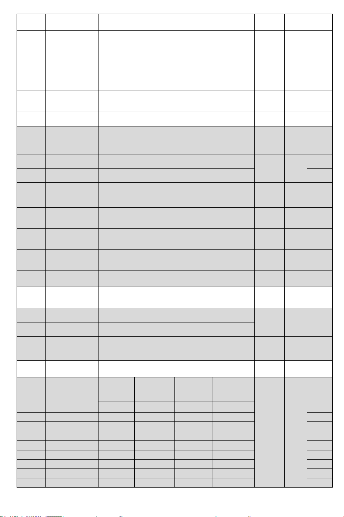
Operation
Selection at
Instantaneous
Power Failure
0: Drive cannot be restarted
1: Drive can be restarted
Auto-Restart
Selection for
Error Trip
Condition
0: Short time interval to auto-restart according to
the setting of F_080 (OC,OE,GF only).
1: Long time interval to auto-restart according to the
setting value of F_080, F_083 (except Fb Lo).
Error Trip
Auto-Restart
Number of time
Set the counting number for drive auto-restart
when errors occur.( OC,OE,GF only)
0: Disable
The setting value is higher and the motor noise is
lower.
0: Ramp to stop
1: Coast to stop
2: Coast to stop + DC braking
Time Interval
before
Auto-Restart
Set the error tripping time interval before drive auto
restarts for F_079 when the drive trips to
stop.( F_079=1)
Pressure Boost
(Water Usage
Detection)
Boost the pressure up to detect if the water is used.
Time Interval of
Pressure Boost
(Water Usage
Detection)
Set the time interval for F_084 to detect if the
water is used.
(0: off)
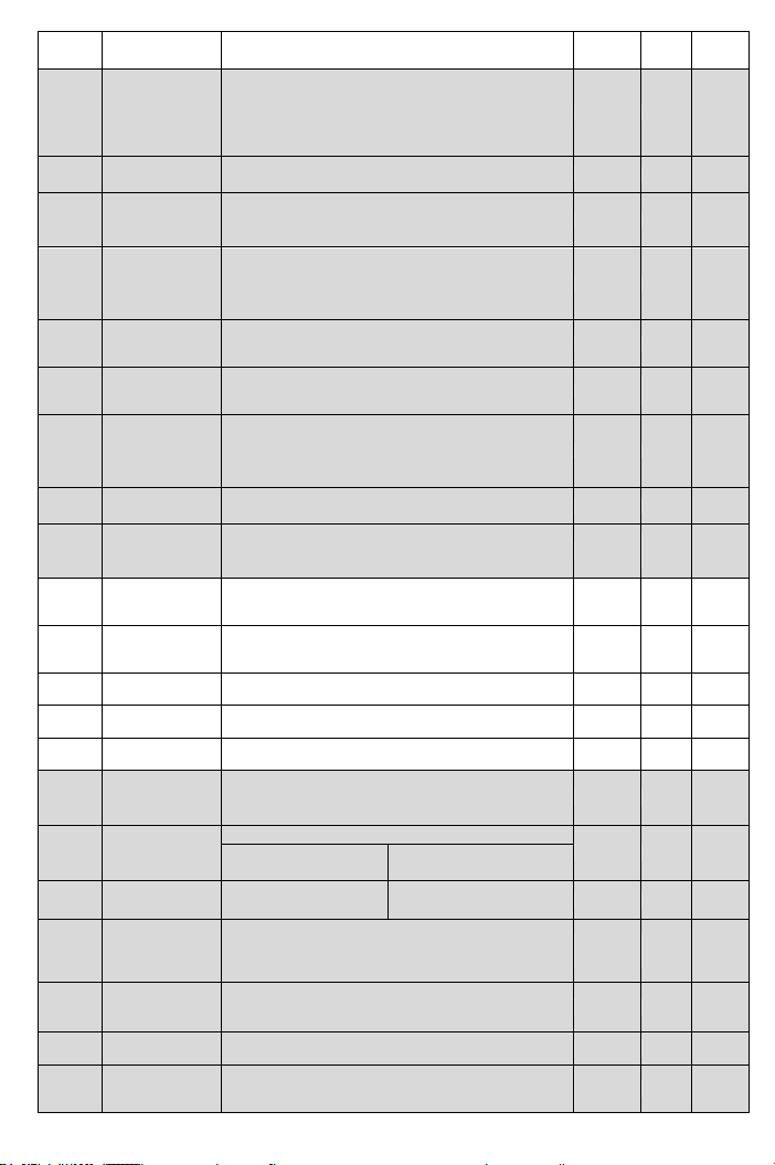
(ON/OFF Mode)
Starting Rate
Setting
In constant pressure control mode and under low
flow condition, setting the starting rate of drive to
activate ON/OFF mode.
Detective time: F_085*(100-F_086)% (0:off)
(ON/OFF Mode)
Pressure Dead
Band Setting
In ON/OFF mode, drive will auto start/stop the
pump in accordance with the setting value.
*Start level=SV(Setting pressure) - F_087
Stop level=SV(Setting pressure) + F_087
Speed Tracing
Current Level
When the current is higher than the “speed tracing
current level”, the output frequency will trace
downward.
0~200% of
drive rated
current
Delay Time
before Speed
Tracing
Set the output delay time before the speed tracing.
V/F Curve in
Speed Tracing
Set the percentage of V/F output voltage at the
speed tracing.
Display the latest 5 error records.
0: Parameters are changeable. Maximum
frequency cannot exceed 120.0Hz.
1: Parameters are locked. Maximum frequency
cannot exceed 120.0Hz.
2: Preserve
3: Preserve
Automatic
Voltage
Regulation
(AVR)
0: Disable
1: Electric thermal protection
2: Current limit overload protection
3: Electric thermal and Current limit overload
protection are enabled.
The value of setting according to the actual power
source.
Analog Input
Signal
Dead Band
When the signal noise is large, appropriately
increase the dead band to stabilize the frequency.
But this will reduce the tuning linearity.