Ricoh PB2030 Operating and maintenance manual

Paper Feed Unit PB2030/2040
Machine Code: D3F1
Installation Procedure
Initial Release: December, 2018
(c) 2018 Ricoh Co., Ltd.
NOTE: THIS UNIT MUST BE INSTALLED BY A CUSTOMER SERVICE
REPRESENTATIVE WHO HAS COMPLETED THE TRAINING COURSES ON THE
BASE MACHINE AND THE UNIT.
Printed in Japan
D3F18610


Symbols and Abbreviations
This manual uses the following symbols and abbreviations:
Symbols:
Screw
Black screw
Connector
Flexible flat cable (FFC)
Hook
Clamp
Clip ring
E-ring
C-ring
Timing belt
Spring
Location of a screw(s) to be tightened or loosened.
Location of a connector(s), clamp(s) or spring(s) to be removed
Direction (Rotating or moving)
Abbreviations:
Abbreviations such as (M1), (S1), or (TH1) after the names of some electrical components indicates
that those components are shown on a Point-to-Point diagram.
Abbreviation Meaning
SEF Short edge feed
LEF Long edge feed
[A] Short edge feed (SEF)
[B] Long edge feed (LEF)


1
Table of Contents
1. Installation Requirements ................................................................................................................... 2
Environment............................................................................................................................................ 2
Machine Level......................................................................................................................................... 3
Minimum Space Requirements .............................................................................................................. 4
Power Requirements.............................................................................................................................. 5
2. Accessory Check ................................................................................................................................ 6
3. Installation Procedure......................................................................................................................... 7
Installing the Single Paper Feed Unit..................................................................................................... 7
Installing the Double Paper Feed Unit ................................................................................................. 12
1.Installation Requirements
2
1. Installation Requirements
Environment
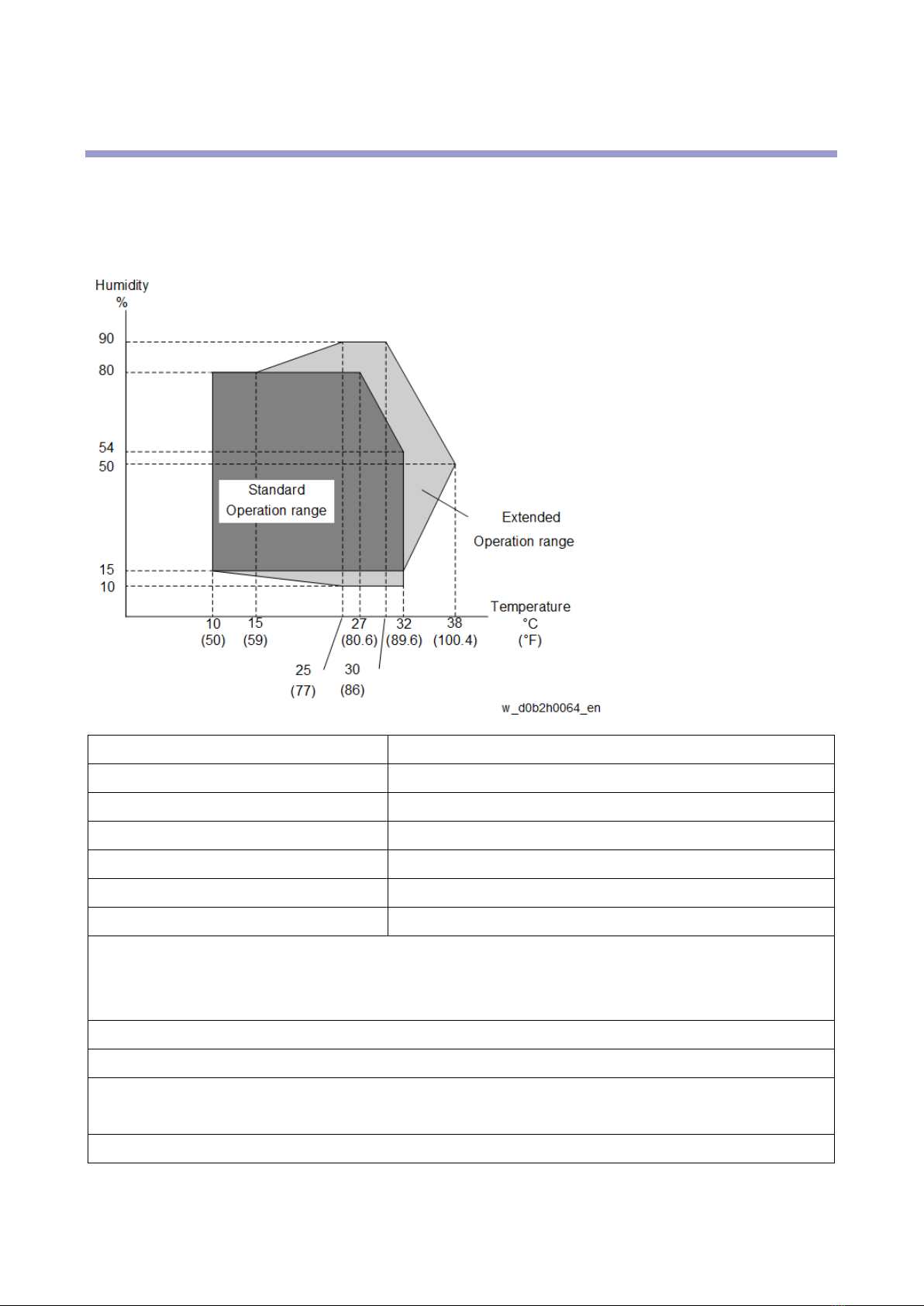
–Temperature and Humidity Chart–
•Standard temperature range: 10 - 32°C (50 - 89.6°F)
•Standard humidity range: 15% to 80% RH
•Extended temperature range: 10 - 38°C (50 - 100.4°F)
•Extended humidity range: 10% to 90% RH
•Ambient illumination: Less than 1,500 lux (do not expose to direct sunlight)
•Ventilation: 3 times/hr/person or more
•Ambient dust: Less than 0.075 mg/m3(2.0 x 10-6 oz/yd3)
•Avoid areas exposed to sudden temperature changes:
1) Areas directly exposed to cool air from an air conditioner.
2) Areas directly exposed to heat from a heater.
•Do not place the machine in areas where it can get exposed to corrosive gases and chemicals.
•Do not install the machine at any location over 2,000 m (6,500 ft.) above sea level.
•Place the machine on a sturdy and level base. (Inclination on any side should be no more than 5
mm.)
•Do not place the machine where it is subjected to strong vibrations.

1.Installation Requirements
3
Machine Level
Front to back: Within 5 mm (0.2") of level
Right to left: Within 5 mm (0.2") of level

1.Installation Requirements
4
Minimum Space Requirements
Place the machine near a power source, providing clearance as shown:
A (front): 750 mm (30")
B (left): 150 mm (6")
C (rear): 300 mm (12")
D (right): 450 mm (18")
The recommended 750 mm (30") front space is sufficient to allow the paper tray to be pulled out.
Additional front space is required to allow operators to stand at the front of the machine.

1.Installation Requirements
5
Power Requirements
•Make sure that the wall outlet is near the machine and easily accessible. After completing the
installation, make sure the plug is firmly inserted into the outlet.
•Avoid using extension cables.
Input voltage:
EU, AP, CHN 220V - 240V, 50/60Hz, 8A

2.Accessory Check
6
2. Accessory Check
Check the quantity and condition of the accessories against the following list.
No. Description Q’ty
1 Relay harness 1
2 Screws 4
3.Installation Procedure
7
3. Installation Procedure
•Turn off the main power switch of the main machine and unplug the power cord before starting
the installation procedure.
•Two or more people are required to lift the main machine. The main machine is highly unstable
when lifted by one person, possibly resulting in injury or property damage.
•Do not lift the main machine with the paper feed unit installed. The grips may be damaged.
Installing the Single Paper Feed Unit
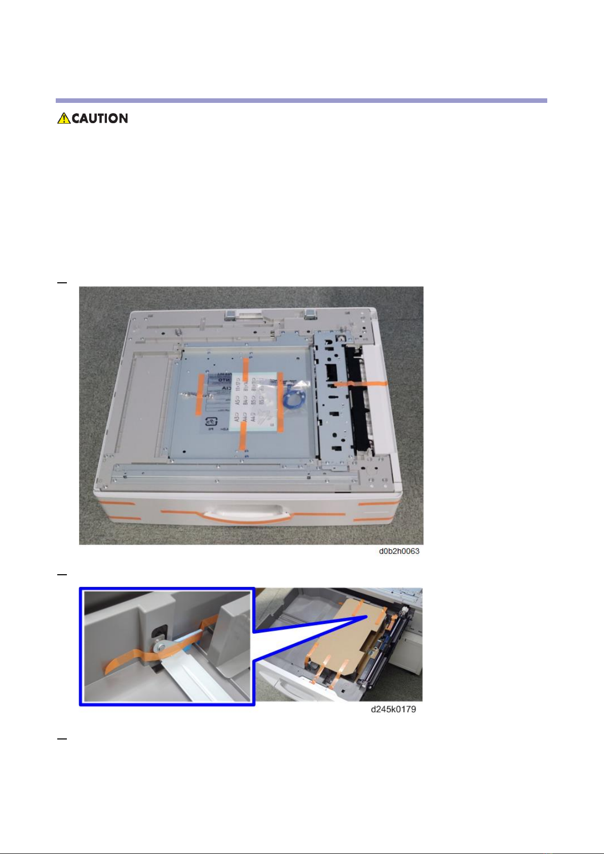
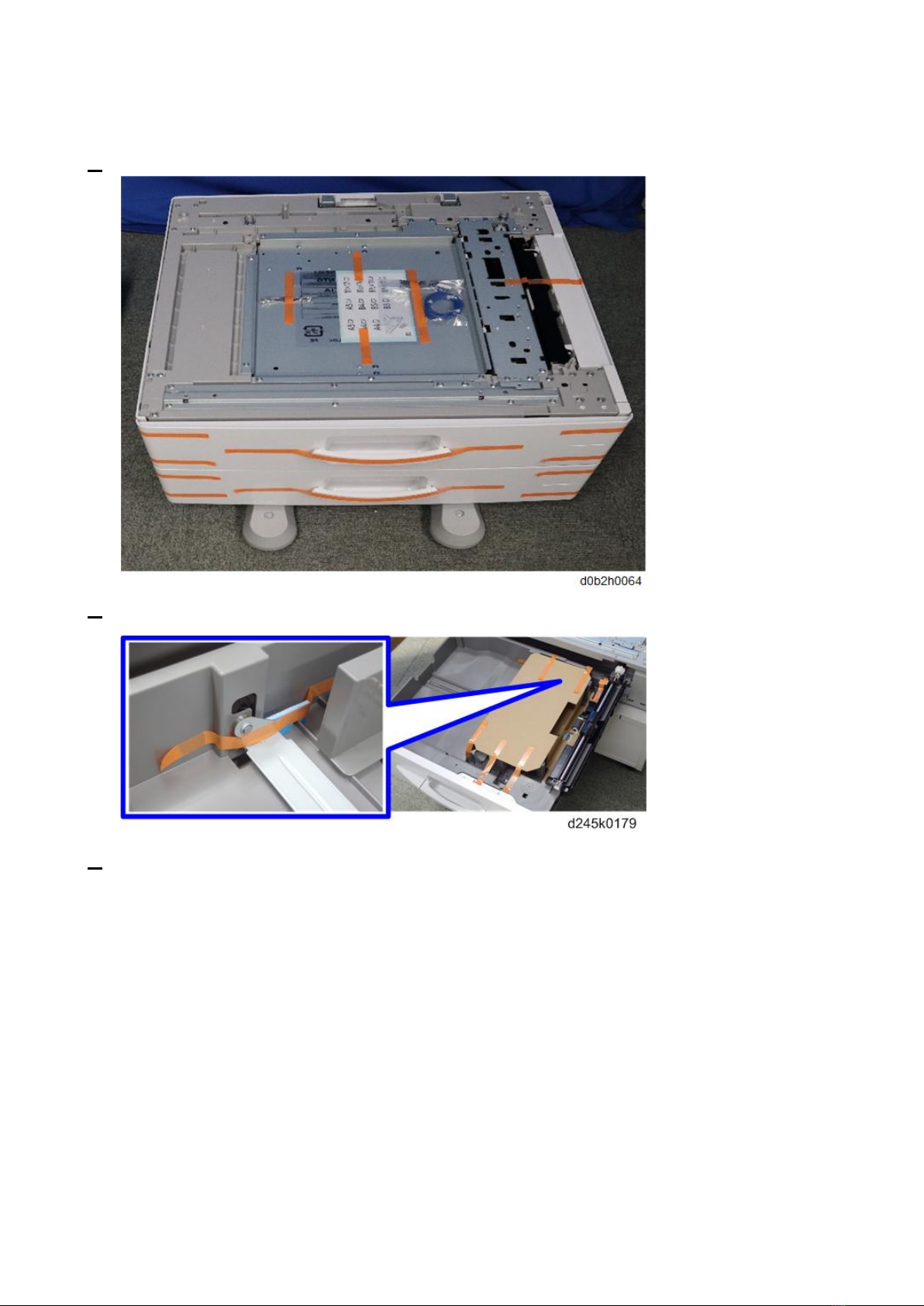
1. Remove all tapes and accessories on the paper feed unit.
2. Pull the tray, and then remove the filament tapes and padding.
3. Lift the main machine and place it on the paper feed unit.

3.Installation Procedure
8
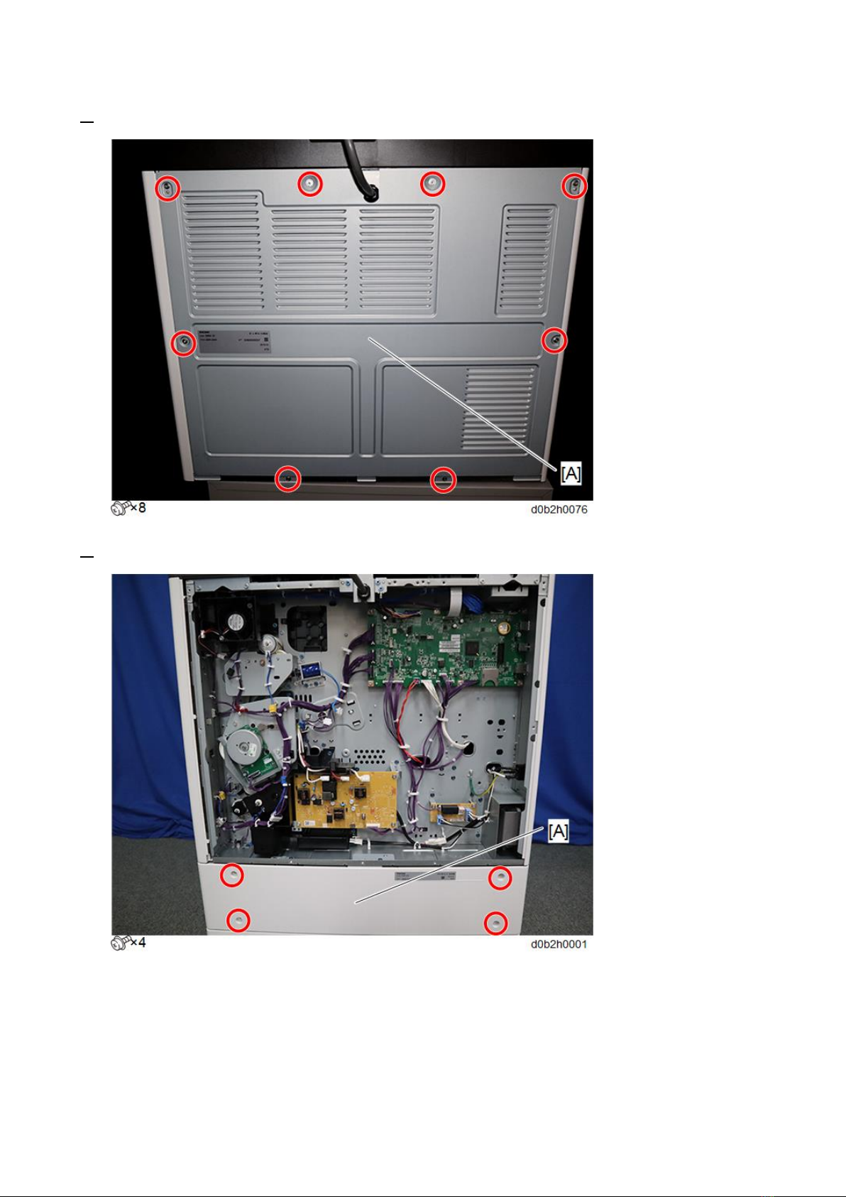
4. Remove the rear cover of the main machine [A].
5. Remove the rear cover [A] of the paper feed unit.
3.Installation Procedure
9
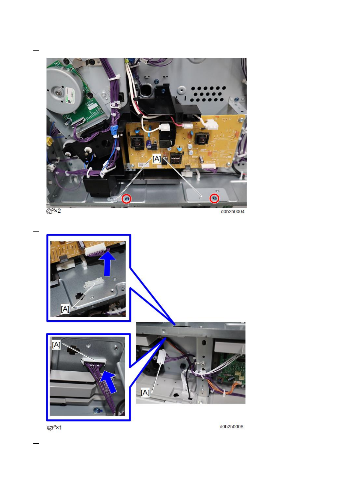
6. Remove the brackets [A] on the bottom of the main machine.
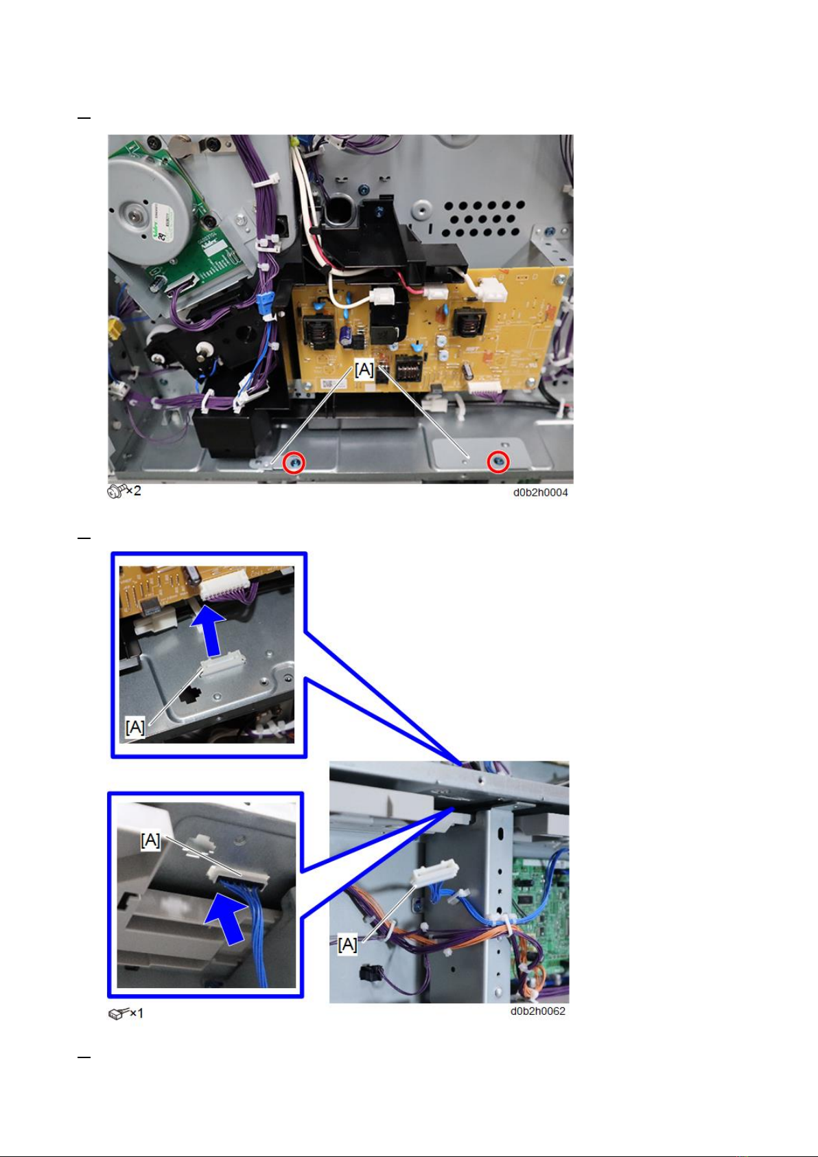
7. Insert the relay harness into the opening [A] of the main machine.
8. Connect the relay harness provided with the paper feed unit to the bottom connector [A] and
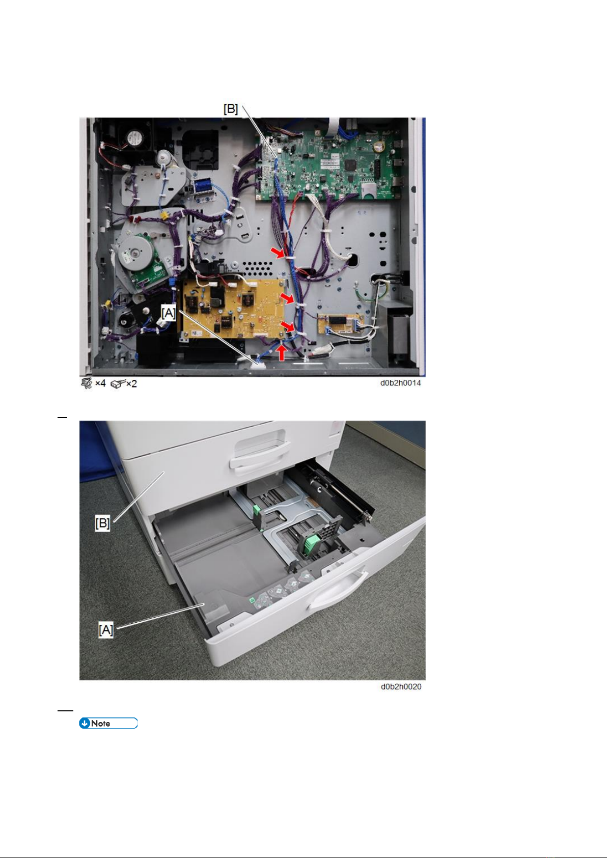
3.Installation Procedure
10
CN246 [B] on the MPU (PCB7) board.
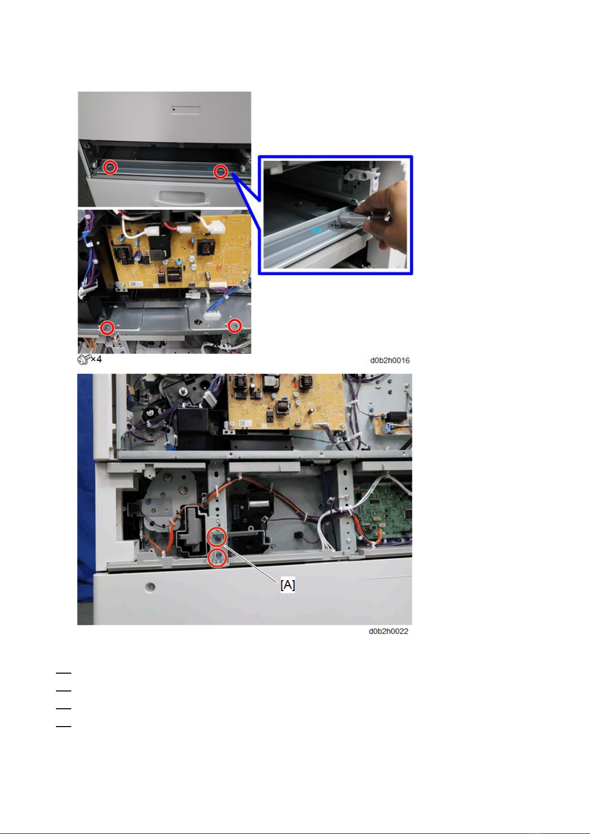
9. Pull out the paper trays [A] and [B].
10. Secure the main machine to the paper feed unit.
Screws (M4 x 6) are provided with the paper feed unit.
Use a stubby driver or the bracket wrench [A] attached to the rear bottom of the paper feed unit.
Reattach the bracket wrench after tightening the screws.

3.Installation Procedure
12
Installing the Double Paper Feed Unit
1. Remove all tapes and accessories on the paper feed unit.
2. Pull the tray, and then remove the filament tapes and paddings.
3. Lift the main machine and place it on the paper feed unit.
3.Installation Procedure
13
4. Remove the rear cover of the main machine [A].
5. Remove the rear cover [A] of the paper feed unit.
3.Installation Procedure
14
6. Remove the brackets [A] on the bottom of the main machine.
7. Insert the relay harness into the opening [A] of the main machine.
8. Connect the relay harness provided with the paper feed unit to the bottom connector [A] and

3.Installation Procedure
15
CN246 [B] on the MPU (PCB7) board.
9. Pull out the paper trays [A] and [B].
10. Secure the main machine to the paper feed unit.
Screws (M4 x 6) are provided with the paper feed unit.
Use a stubby driver or the bracket wrench [A] attached to the rear side of the paper feed unit.
3.Installation Procedure
16
Reattach the bracket wrench after tightening the screws.
11. Reinstall all trays and covers.
12. Load paper into the paper feed unit.
13. Turn on the main power switch of the machine.
14. Adjust the registration of the upper paper feed unit. (Adjustment after Replacement)
•Use SP1-002-005 for the tray bank 2.
Other manuals for PB2030
1
This manual suits for next models
2
Table of contents
Popular Range manuals by other brands


KitchenAid
KitchenAid W10524723A manual

Haier
Haier QCAS70 user manual

Thermador
Thermador Pro Grand PRD364WDGC installation instructions

Thermador
Thermador Professional PRO-HARMONY PRD30 installation manual

Jenn-Air
Jenn-Air Dual Fuel Updraft Slide-In Range installation instructions

Plamen
Plamen Termo Glas Installation and operating instructions

Frigidaire
Frigidaire FFGF3015L M Brochure & specs

Frigidaire
Frigidaire FEF357CGSA owner's guide

GE
GE JGAS24 Use and care & installation guide

Viking
Viking Professional Custom VGCC5366BSS installation guide

Electrolux
Electrolux Frytop EFT7 Series Installation and operating manual

Jenn-Air
Jenn-Air JER8885RAB Use & care guide