Rinieri Velox Series Specification sheet

Velox
1-2-5-8 GS-GE
In and out groups mount frame
Instructions for use and maintenance
The following instructions must be read carefully prior to using the machine.
In accordance with article 2006/42/CE
and subsequent modifications
SERIAL

In regards to safety and reliability this machine was designed in accordance with the provisions and subsequent
revisions set out in the EEC “machines article”.
The manufacturer therefore cannot be held responsible for machine use where modifications have been made without
prior manufacturer’s consent, replacement parts used are not those stated by the manufacturer and use by untrained
persons.
For safety issues not covered in this text please refer to general standards concerning the prevention of accidents.
Below is a list of definitions, descriptions and abbreviated terms most frequently used in the text.
Mass. = weight of object or machine
A.P.
B.P.
min.
max.
1'
h
L
P
H
Fig.
Pag.
Autom.
Man.
Rif.
Hp
°C
kg.
m.
cm.
mm.
CEE
high pressure
low pressure
Minimum
Maximum
minutes
hours
width
depth (length)
height
figure
page
Automatic
Manual
Reference
Horsepower
centigrade
kilograms
meters
centimeters
millimeters
European Economic Community

EC DECLARATION OF CONFORMITY
As stated by the EC directive 2006/42/CE and subsequent modifications
The undersigned
RINIERI S.r.l. - Forlì –Italia - Viale dell’Appennino 606 B
Declares under its responsibility that the machine:
Velox
Model
Code no.
Serial no.
Is in accordance with essential health and safety requirements of the machinery directive 2006/42/CE and its
subsequent modifications.
For the verification of conformity to the directive mentioned above, the following directives were respected:
UNI EN ISO 12100:2010
Safety of machinery - General principles for design - Risk assessment and risk reduction
UNI EN ISO 4254-1:2015
Agricultural machinery –Safety –Part 1: General requirements
UNI EN ISO 4254-5:2010
Agricultural machinery - Safety - Part 5: Power-driven soil-working machines
Forlì,
Person authorized to compile the technical file
Mr. Carlo Rinieri
Signature ---------------------------------------------------

Page intentionally left blank

ATTENTION
THE PURPOSE OF THIS TEXT IS TO INTRODUCE YOU TO THE
BASIC STANDARDS AND CRITERIA YOU HAVE TO FOLLOW IN
ORDER TO USE AND MAINTAIN THIS MACHINE AND THUS IT
HAS TO BE READ BEFORE USING THE MACHINE.
This manual has to be considered as an integral part of the machine and must be passed on with the machine if resold.
If you loose it or if it is not readable, it is important that you ask for a new copy to the producer, to the dealer or to the
importer.
If you think that some themes are not very good illustrated, return to the producer, the dealer or the importer to have
the needed informations.

INDEX
DESCRIPTION
Declaration of conformity
Index
Introduction
General information
Recommendations
Description of the machine
Use
Pre-operation
Controls
Identification data
Adhesives
Safety regulations
Improper use
Incorrect use
Method of use
Registration
Maintenance
Transport hoisting movement
Spare parts
Conditions of guarantee
Page
3
6
7
7
7
8
11
11
13
15
15
17
18
18
18
20
20
22
23
24

INTRODUCTION
Dear Customer,
the purpose of this text is to introduce you to the basic standards and criteria you have to follow in order to use and
maintain this machine and thus it must be read before using the machine.
If any part of this publication is not understandable please consult your retailer as this is a necessary precondition to
using this machine safely.
Your safety depends on your careful and rational observation of the standards laid out in the text as well as the proper
functioning and durability of your machine.
This manual must be considered as an integral part of the machine and must be passed on with the machine if
resold.
This publication contains all the general specifications needed to have a working knowledge of the machine without
regards to specific types, models and the numerous characteristic modes and settings.
GENERAL INFORMATION
INSTRUCTION MANUAL
Verify that this manual is in good condition and all pages are readable.
If damaged or missing pages on receipt, please return to the retailer who will provide a replacement copy.
PRESERVATION AND CARE OF MANUAL
This manual must be kept for the entire life of the machine.
If lost of destroyed please ask the manufacturer for another copy quoting the type of machine, serial number and year
of production.
IN HOUSE TESTING
The machine has been tested on the manufacturer’s premises to verify that all components function correctly
according to standards laid out by the standards in force.
DELIVERY
Responsibility for goods in travel lie solely with the transporter and recipient.
In cases of delayed delivery or accident and the manufacturer cannot be held responsible.
Transportation of goods has to be carried out by suitable companies who comply to regulations in force and legislation
concerning weights and bulks.
INSPECTION
On receiving the machine check the condition.
Should you come across any damages don’t install the machine, instead inform the supplier and transporter
immediately.
Make sure the machine is in good condition.
Check you have all components, the overall condition of the machine is good and there are no breakage or dents.
In cases of damages or missing components inform the retailer immediately after taking legal proceedings against the
transporter, if necessary.
PACKAGING
Packaging material and maintenance waste must be disposed of separately at authorized depots and not left in reach of
children or animals or to litter the environment.
MACHINE DETAILS
An exact model description, identification code, serial number and any installed accessories will help the
manufacturer or call center deal with any enquiries quickly and efficiently.
Always refer to the machine model and production dates every time you contact the call center, retailer or
manufacturer.
For quick reference fill in your machine details in the box below
MODEL:
Velox 1/130
SERIAL NUMBER:
21417
CODE:
6GE126
YEAR OF PRODUCTION:
2013
RECOMMENDATIONS
Before use please read the instructions carefully, in particular the RECOMMENDATIONS, SAFETY
REGULATIONS and PRECAUTIONS.

We remind you that some machines mechanical parts have linear or rotatory movement and can cause serious damage
or injury to people, animals and things.
It is forbidden to remove or tamper with the safeguards of the machine.
It is obligatory to wear the correct protective clothing and safety equipment.
It is necessary to keep the machine clean and in working order especially the nameplates, couplings and controls.
For the safety of you and others and the proper functioning of the machine don’t use the machine for uses other than
those specified or intended by the manufacturer.
Before using the machine make sure that any dangers to your safety or others have been removed. Pay attention to the
type of oil of used in cases where the equipment is used with different types of tractors.
VERY IMPORTANT
For all operations use proper working clothes and/or suitable safety apparel like glasses, shoes, gloves, and
working cloth in accordance with the safety standards in force in the working area.
The working area must be kept completely clear, so pay the utmost attention that there aren’t any people or
animals in the immediate area.
Nobody else apart from the operator must be within the working zone other than collaborators which for
safety should be no less that 50 mtrs.
Maintenance of the equipment must be carried out by only one operator with the machine off and tractor at a
standstill (off) with the ignition key removed.
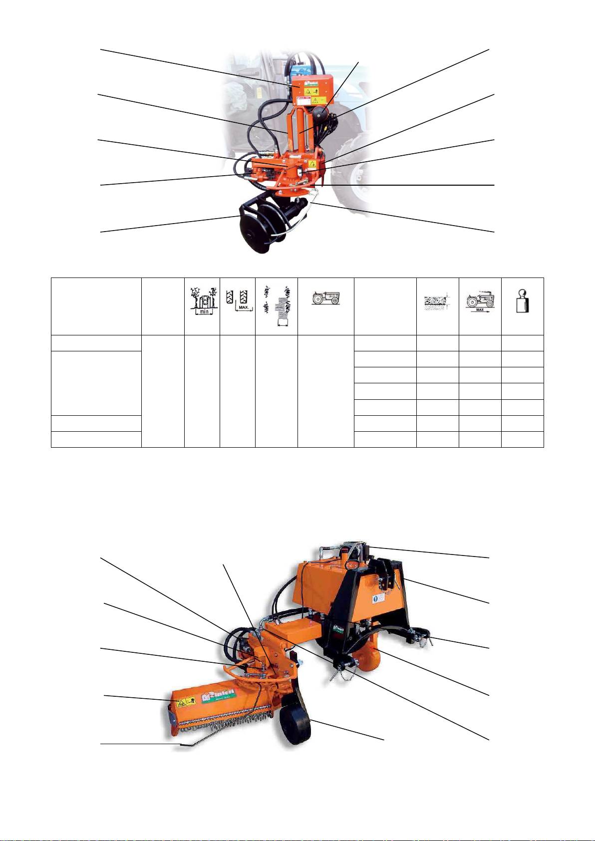
MACHINE DESCRIPTION
The in and out group “GS-GE” (Fig.1) is attached to other tools.
The tool avoids the plants by rotating at a 90° angle through a double acting hydraulic jack (Fig.3) operated by a
sensor rod (Fig.4). The pushing force that is necessary is provided by the independent hydraulic system of the tractor.
The distributor (Fig.5) receives the command for avoiding the plant through the sensor rod that works automatically
and the emergency control can be mechanic, hydraulic “I” (Tab.4/A) or electro-hydraulic with proximity sensors
(Fig.6).
In addition to the right hand version, also a left hand version is produced.
It works on the left hand side of the tractor; when used together, it is possible to work on two rows simultaneously.
On request, it is possible to have a version with a turning front wheel either with a disc or without with mechanic
setting (Tab.3) that helps to proceed in a straight line.
5
1
4
6
3
2
The in and out group “GS-GE” (Fig.1) is either attached to a supporting frame that can be applied to the rear or front
three point hitch or normal tractors or it can be attached laterally to the tractor by a coupling frame.
The pushing force that is necessary is provided by the independent hydraulic system or by the tractor.
The side mounted version, the machine has a fixed side mounted frame (Fig.7). The side shift and vertical lift can be
hydraulic with hoses to the tractor (Fig.9).
The machine also has an independent hydraulic system with oil cooler if needed (Fig.10), hydraulic tilting of the
working head with hoses to the tractor (Fig.11) and accumulator (Fig.13) for turning the working tool floating.
On request, it is possible to have a version with a turning front wheel either with a disc or without with mechanic
setting (Tab.3) that helps to proceed in a straight line.
10
7
1
5
2
9
11
6
3
4
Codice
Mod.
Mt.
Mt.
HP - KW
Tools
Mt.
Km/h.
Kg.
6GS511 - 6GE511
Velox
5
2,50
2,00
0,60
50 - 37
Blade
0,15
10
310
6GS515 - 6GE515
Discs
0,15
6
350
SRV
/
6
335
RSI
/
4
340
RFC
0,10
4
345
6GS516 - 6GE516
Harrow
0,10
4
365
6GS514 - 6GE514
TRA
/
4
350
The simple version of the machine has a fixed three-point hitch (Fig.7) and a supporting rear wheel with regulation
by screws (Fig.8). The side shift can be mechanical or hydraulic with hoses to the tractor (Fig. 9).
The machine also has an independent hydraulic system with oil cooler if needed (Fig.10), hydraulic tilting of the
working head with hoses to the tractor (Fig.11) and a turning front wheel with a disc or a fixed smooth front wheel
with mechanical regulation (Fig.12) in order to make it easier to drive in a straight line.
5
1
6
2
4
10
7
9
8
11
12
3
13
Mt.

Code
Mod.
Mt.
Mt.
HP - KW
Tools
Mt.
Km/h.
Kg.
6GS121 - 6GE121
Velox
1
130
1,50
1,70
0,60
40 - 30
Blade
0,15
10
340
6GS125 - 6GE125
Discs
0,15
6
390
SRV
/
6
365
RSI
/
4
370
RFC
0,10
4
375
6GS126 - 6GE126
Harrow
0,10
4
455
6GS124 - 6GE124
TRA
/
4
440
6GS221 - 6GE221
Velox
2
130
2,50
2,50
0,60
50 - 37
Blade
0,15
10
360
6GS225 - 6GE225
Discs
0,15
6
410
SRV
/
6
385
RSI
/
4
390
RFC
0,10
4
395
6GS226 - 6GE226
Harrow
0,10
4
485
6GS224 - 6GE224
TRA
/
4
470
6GS231 - 6GE231
Velox
2
180
3,00
3,00
0,60
50 - 37
Blade
0,15
10
370
6GS235 - 6GE235
Discs
0,15
6
420
SRV
/
6
395
RSI
/
4
400
RFC
0,10
4
405
6GS236 - 6GE236
Harrow
0,10
4
495
6GS234 - 6GE224
TRA
/
4
480
The double version of the machine has a fixed three-point hitch (Fig.7). The side shift is hydraulic with hoses to the
tractor (Fig.9). The machine also has hoses to the tractor or an independent hydraulic system with an oil cooler if
needed (Fig.10), mechanic tilting of the working tool (Fig.11) and a turning front wheel with a disc or a fixed smooth
front wheel with mechanical regulation (Fig.12) in order to make it easier to drive in a straight line.
On demand, it is possible to have a version with a pair of hydraulic cylinders with a distributor in order to replace the
mechanic tilting of the working head with a hydraulic version.
5
1
6
2
4
10
7
9
11
12
Mt.
3

Codice
Mod.
Mt.
Mt.
HP - KW
Utensile
Mt.
Km/h.
Kg.
6GE811
Velox
8
100
S
180
110
0,60
50 - 37
Blade
0,15
10
280
6GE815
Discs
0,15
6
580
SRV
/
6
550
RSI
/
4
560
RFC
0,10
4
570
6GE816
Harrow
0,10
4
650
6GE814
TRA
/
4
620
6GE821
Velox
8
115
L
240
140
0,60
50 - 37
Blade
0,15
10
300
6GE825
Discs
0,15
6
630
SRV
/
6
600
RSI
/
4
610
RFC
0,10
4
620
6GE826
Harrow
0,10
4
700
6GE824
TRA
/
4
670
For all models, on demand, it is possible to have a version with a mouldboard for the hoeing blade, a spatula that
cleans the plants and/or a soil-levelling blade for the disc unit, a front wheel with hydraulic regulation with hoses to
the tractor instead of the mechanical regulation.
For the GS version, for all the models mounted to the support frame, there is a version with a hydraulic distributor
with 1, 2 or 3 levers that can be put next to the drivers seat for using the movements of the machine parts with tractors
without levers.
For the GE version, there is a safety control with 1 or 2 controllers with 2 movements for commanding all the parts of
the machine.
USAGE
It is a machine suitable for the work in vineyards and orchards and allows to cut, to weed, to hoe up and to earth up
the grass in between the plants.
The in and out group can be equipped with different tools according to the kind of work to be done:
- hoeing blade for weeding between plants (Tab. 2/A).
- hoeing and ridging discs (Tab. 2/B).
- Shredder “ TRA “ to cut grass between the plants (Tab. 2/C).
- Side shoot remover “ SRV “ for vine suckering and weeding between the plants (Tab. 2/D).
- hoeing blade with rear and front disc unit, soil-levelling blade and flat disc for the weeding, hoeing and ridging
between the plants (Tab. 2/E).
- rotating power harrow head for a light tillage and uprooting between the plants (Tab. 2/F).
- Mower wheel “RSI” to cut grass and for complete weeding between the plants (Tab. 2/G).
- Roto-tiller “RFC” head for a light tillage and grass removal between the plants (Tab. 2/H).
PRE-OPERATION
In the single 1 configuration, there are n.2 attachment positions for the displacement jack to the lifting unit, in the
single 2 configuration there are n.3 attachment positions. For reason of space, the machine is assembled using the
innermost attachment in the 1 and 2/130 configuration and the central attachment in the 2/180.
When using the machine, make sure you use the most suitable attachment position based on the equipment model you
possess.
To avoid damaging the equipment, for model in the 1 and 2/130 configuration, only use the innermost attachment
position or the central one while for model in the 2/180 configuration, only use the central or outermost attachment
position.
Never use the outermost attachment for model in the 2/130 configuration because it is reserved exclusively for model
in the 2/180 configuration.
Mt.
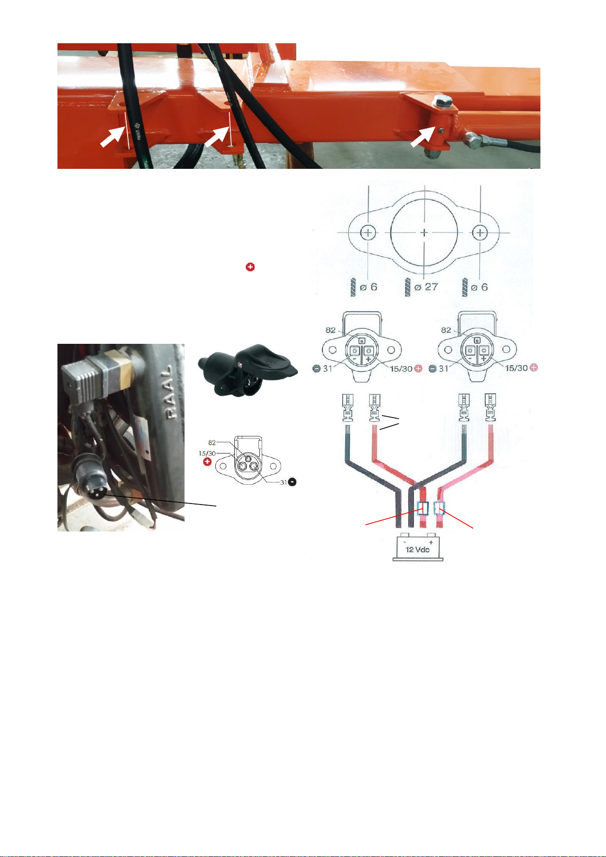
If the tractor does not have any 3-pin plug attachments,
adapt its system with the same 3-pin plugs that come with
the machine considering the scheme here on the side.
Connect the two 4mm2diameter cable groups with max.
impedance 18A directly to the 12V battery of the tractor,
one group for every 3-pin attachment to add to the existing
system.
For every group insert on the red power cable a 20A
fuse for the 3-pin plug of the oil cooler and a 10A fuse to
the 3-pin plug on the control panel.
Connect the 3-pin plugs to the tractor using the piercing
mask printed on the blister, then connect the cables to the
3-pin plugs paying attention to respecting polarity.
3 pin power plug
3-pin plug
of the oil cooler
The machines that we deliver personally or pack and ship partially assembled are provided with grease in the
hydraulic system, bevel gears, and gearbox, unless directed otherwise; they are tested thoroughly after assembly by
having them turn at full speed and the hydraulic ram end stops have been adjusted.
If indicated by the corresponding label, in order to prevent hydraulic oil from leaking from the hydraulic system’s
tank, substitute the closing top from the hydraulic tank’s hose with a top with vent/air filter with the machine in a
perfectly horizontal position.
If the machine is delivered without hydraulic oil in the hydraulic unit’s tank (this will be indicated in the
accompanying documentation), it is necessary to fill it before starting to use the machine.
Use a mineral oil grade ISO VG 46 for hydraulic units like, for example, Mobil DTE 25 and a discharge/aspiration
oil filter with metal net of µ60 with a flow of 54 L/min.
Make sure that all levels are equal to those described in the MAINTENANCE chapter.
Apply the GS-GE to the tool using the coupling frames (Fig.8 Tab.1/A and 13 Tab.1/B).
Apply the machine to the tractor using appropriate pins (Fig.50 and 52 or 4 and 7, Tab.6) and, if necessary, use
adaptor bushings.
The tractor should be heavy enough to counterbalance the machine when it is fully hoisted so that the front tires do
not lose their grip.
Lift the machine up as high as possible and tighten the arms until there are not more than 5 cm. margin left; It is
absolutely necessary that the third point is at the center of the tractor.
Set the top link of the tractor’s three-point-hitch when the machine is resting on its wheels or skids by lengthening or
shortening the top link until the machine results completely horizontal.
Crimp
or sold
Fuse
10A control
panel
Fuse
20A oil
cooler
If it is not included with the machine, connect an adequately powered cardan shaft making sure the side with the
picture of a tractor is inserted in the tractor’s power take-off. The safety device, the shear bolt, should be applied only
on the machine’s side.
Secure the shaft’s safety casing to the tractor and to the machine using the appropriate anti-rotational chains; Never
use the shaft without its safety casing and without having secured it with its respective chains.
Find the position in which it the cardan shaft is shortened the most in the various shifting movements, making sure it
can still be shortened an extra 5 cm.
Before installing, using or performing maintenance operations on the transmission, read all the instructions
contained in its manual, as well as those provided by the tractor and other equipment manufacturers.
For the side mounted model, apply the universal coupling frame (Fig. 1 Tab.6) to the tractor, apply the machine to the
tractor with the pins (Fig.3 Tab.6) and, if present, apply the hydraulic pump to the PTO and fix it with its chain.
Tie a rope to the emergency lever (Fig.78 Tab.1/A) for the manual side shift control and fix the lever to the tractor if
the control is hydraulic (Fig.B Tab.4/A). Connect the 12-Volt cigarette-lighter power plug to the tractor if the
emergency control is electrohydraulic or connect the 12-Volt 3-pin power plug to the correct 3-pin power outlet of the
tractor if there is an oil cooler.
Insert the hydraulic hoses of the movements into the fast-joints of the tractor.
Slowly start the power take-off up to a maximum of 400 turns in the range of 540 rpm; be careful as the working tool
will open automatically.
In the case of the machine with proximity sensors, when the selector on the emergency control box (Fig.73 Tab.1/B)
is in the working position, the working tool will open automatically in the same way. If the selector is put in the
closing position, the tool closes and remains closed with the controls of the box and of the sensor rod deactivated until
the selector is put back into the working position.
By pulling the rope and thereby activating the hydraulic lever, or by pressing the red mushroom push-button of the
emergency control box, the tool is closed and remains so as long as the rope remains tight or the push-button remains
pressed.
Caution: on the single side model with power harrow or shredder it is possible to add a lever distributor that is used to
start or exclude the motor of the working tool.
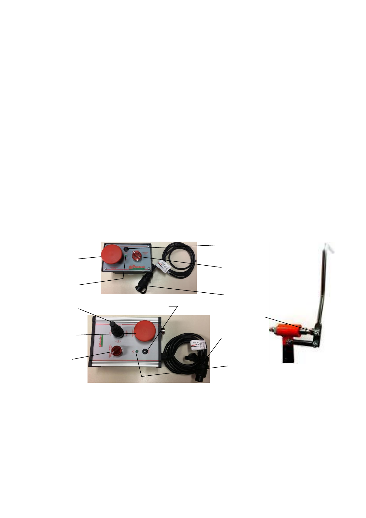
CONTROLS
Red mushroom
push-button
Green status
light
Controllers
Red mushroom
push-button
Selector
working/closing
Fuse holder
Fuse holder
Selector
working/closing
3-pin plug
Hydraulic lever
3-pin plug
Green status
light
By connecting the 3-pin plug to the tractor the control panel is activated and the green status light lights up.
If the green status light does not turn on, it might be for one of the following reasons:
- there might be no power or polarity in 3-pin plugs that have been added to the tractor’s system might be inverted.
- there might be a burned fuse in the control panel.
- there might be a burned fuse in the connection of the 3-pin attachment on the tractor.
Switch the selector of the emergency control box to working position and the machine will automatically shift
completely to the right. If you bring the selector in the closed position, the machine will close itself shifting
completely to the left and remain closed, disactivating the emergency box comands as well as the sensor rod comands,
as long as the selector is not switched back to the working position.
If you use the hydraulic lever, or press the red mushroom push-button of the emergency control box, the machine
closes and shifts completely to the left as long as the lever remains active or the push-button remains pushed.
When work is finished disconnecting the 3-pin plug from the tractor, the electricity supply of the control panel is
interrupted and the green status light turns off.
The fuse holder contains a glass fuse 5x20WF 10A 250V.
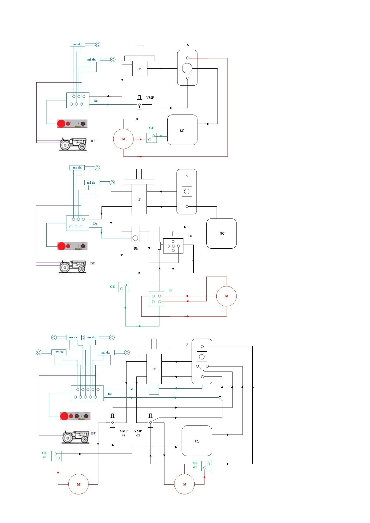
CONNECTIONS AND HYDRAULIC SCHEME
Single version 50 and
90 liters
S: Oil tank of the
hydraulic kit
P: Pump
SC: Oil cooler
VMP: Maximum
pressure valve
RF: Flow divider
Di: hydraulic distributor
De: electro-hydraulic
distributor
B: electro-hydraulic
commando block
GE: electro-hydraulic
commando block GE
ms: displacement
cylinder
mi: inclination cylinder
DT: tractor’s distributor
M: Motor
Double version 90 liters
with discs and power
harrow
S: Oil tank of the
hydraulic kit
P: Pump
SC: Oil cooler
VMP: Maximum
pressure valve
De: electro-hydraulic
distributor
Br: electro-hydraulic
commando block with
flow divider
GE: electro-hydraulic
commando block GE
ms: displacement
cylinder
mi: inclination cylinder

DT: tractor’s distributor
M: Motor
IDENTIFICATION DATA
ATTENTION
CHECK YOUR MACHINE: if you don't find an identification tag, ask immediately for it to your retailer.
Machines without identification tag mustn't be used. Our factory doesn't recognise them, so consider them as
anonymous and potentially dangerous.
Identification tag should always be attached on the machine and should be well readable, so, if it deteriorates or if you
loose it, please ask the manufacturer or your vendor buy a new one.
Identification tag of the machine
The identification tags are little plates fixed to the machine
frame and it supplies the following information:
A
Manufacturer
3
Serial
1
Model
4
Bulk
2
Code
5
Year of construction
ADHESIVES
The following safety adhesives are placed on the machine for your safety and the safety of others.
Go through the manual taking note of the meaning of every warning or danger sign.
This procedure has to be done together with your fellow operators and anyone using this equipment.
If in the event that one of these adhesives goes missing or becomes illegible you must get an immediate replacement
by contacting your retailer, or the manufacturer.
Indicates the equipment’s place of origin;
built or assembled in a country that belongs to the
European Economic Community

CAUTION
The power takeoff must be set to 540 rpm
with a working speed between 280 and 400 rpm.
CAUTION
Read and refer to the “use and maintenance” instruction manual
carefully before using the equipment or performing any kind of work
on it.
CAUTION
Danger: machinery may suddenly shift laterally.
Keep safety distance.
Hook for hoisting and handling the machinery.
Indicates the areas that require grease injections.
Indicates the different types of lubricant that must be used on the
various machinery components.
Indicates the ideal oil level in the hydraulic system’s
oil reservoir.
CAUTION
Danger: rocks or ground particles may be expelled from the machinery
while it is in use.
Keep safety distance.
CAUTION
The machinery contains sharp rotating tines;
Keep safety distance and wait for the components to stop rotating
before performing any work on them.

CAUTION
The machinery contains rotating equipment;
Keep safety distance and wait for the components to stop rotating
before performing any work on them.
CAUTION
The machinery contains rotating equipment;
Keep safety distance and wait for the components to stop rotating
before performing any work on them.
CAUTION
Suitable safety individual equipment must be worn.
SAFETY REGULATIONS
The use of this machine is for skilled and specialized persons with appropriate abilities and competence in carrying
out operations.
The must have a good knowledge of this manual and are informed in general safety procedures.
Follow with the utmost care and attention instructions for your safety, the safety of others and of environment.
SYMBOLS TO REMEMBER
Danger for people
Danger of serious damage to the machine
General danger
Protect the environment
The operator must always stay in the drivers seat and never abandon it when the equipment is on and
the engine is on.
The operator must never leave the drivers seat with the aim of making adjustments or other reasons
as it could create a dangerous situation.
The operator must always stay in the seat alone and not carry other people animals or things.
The operator must wear appropriate work overalls / clothes and not loose clothing which could get
caught in moving parts of the vehicle or equipment causing serious injury.
It’s necessary to wear personal protective devices for eyes (face mask, goggles) and protective
headphones for acoustic pressure in places of work it is greater than 85 db.
Don’t wear rings, wrist watches, loose articles of clothing or hanging things, torn clothes, shoes,
unbuttoned jackets or blouses which can get caught in moving parts. We advise you to use approved
articles of clothing for accident prevention for example sturdy gripped boots, safety goggles and face
mask, above all if the vehicle is automatic without a cabin.
We advise you to consult the appropriate public authority concerning the acquirement of accident
prevention devices and vineyard safety.
The operator must have suitable abilities and psychophysical conditions in order to understand how
to apply correctly all the instructions specified in this manual and all the symbols and captions on
the machine.
Do not use the machine if you are under the influence of medicines, alcohol, or other substances that
could compromise your normal level of attention, perception and reaction.
When on the streets, respect meticulously the provisions in force, in particular as far as lighting,
safety devices, maximum dimensions, juts etc are concerned.
Drive very carefully because the equipment limits visibility.
When you have to drive on streets to reach the work place, make sure that the machine is in line with

the moving vehicle and that it does not cover possible lighting and signaling systems; if this is not
possible, put the machine on a type-tested tow.
Before leaving the driver’s seat, disconnect the power source, switch off the engine, take out the
ignition key and put on the handbrake.
Do not allow the machine to be used by any operator ignoring the risks and instructions reported in
this manual.
Keep the equipment clean and in order.
Do not use any equipment with faulty components.
Additional safeguards have been placed by the manufacturer for the safety of the operator during his
work; their removal or tampering is therefore absolutely forbidden; instead, always make sure that
safeguards and safety devices are in place and work properly.
For the operator’s safety and the equipment’s integrity, do not modify anything without the written
authorization of the manufacturer.
Make sure that no one is in the working area of the machine when in use, (minimum distance to
respect: at least 50 meters), pay much attention to children and animals.
Verify the stability of the machine on a flat while the machine is working.
Do not work on soft ground, on too extreme slopes or that can compromise the machine’s stability.
Remove possible obstacles as wood, tree trunks , scraps which could damage the machine and its
stability.
Clean your shoes’ soles before getting up the machine and using the pedals.
Do not try to take out material with tools or with hands or feet while the machine is working: stop
the tractor, switch off the PTO, take off the key and wait some minutes that the machine stops before
repairing it.
If you have to stop while working, stop the machine on a flat with operated hand brake and first
speed, disconnect the PTO, turn off the motor and take out the key.
Be always sure that every part of the hydraulic kit is well closed.
Do not tamper the security system.
The security of your machine depends on its efficiency , so respect the instructions and the
maintenance. on its efficiency , so respect the instructions and the maintenance.
IMPROPER USE
By improper use we mean:
-using the machines for operations they were not designed for or for usages that do not appear in the chapter
“Machine’s Description and End Use” of this manual;
-use of the machine by people under the age of 18, and/or people not trained to use this kind of equipment.
INCORRECT USE
By incorrect use we mean using the machines without respecting the instructions of the manual.
Not respecting these instructions could risk injury to the operator or third parties, and cause damage to the machine.
Incorrect use can thus mean:
-incorrect installation and/or use of the components or optional accessories.
-incorrect preparation of the machine.
-not using the manufacturer’s spare parts.
-repairs by non-authorized people.
-maintenance by non-qualified people.
-uses the machine is not designed for (see above), lack of maintenance.
WARNING: the manufacturer cannot be held responsible for any injury to people, animals or damages to
things resulting from improper or irresponsible use, as mentioned above.
METHOD OF USE
Users
Users are divided into two categories:
- OPERATOR: a person without technical knowledge but trained to use the machine and carry out simple
maintenance and adjustments.
- QUALIFIED TECHNICIAN: a person who works on behalf of the manufacturer and/or retailer and can carry out
complex maintenance and repairs.
Indications before using
Before starting the machine, you should read this manual carefully.
Check that everything has been installed and checked by a qualified technician.

Send away everybody from the working area before starting work, than proceed slowly checking your machine.
Make sure there are no people standing near the machine. With the machine lifted up in a perfectly horizontal position
slowly start up the power takeoff until it reaches a maximum of 400 turns within the 540 rpm range and make sure
that everything is working properly and without vibrations. If the machine does not have a hydraulic tank, activate the
tractor’s hydraulic system and bring the lever that commands the circuit in an open position.
The advancing speed differs according to the working tool that is used.
Use an advancing speed between 6 and max10 km/h with the hoeing blade, between 3 and max 6 km/h with the discs
and the side shoot remover and between 2 and max 4 km/h with the mini-shredder, the mower wheel and the roto-
tiller.
On the model with power harrow or shredder it is possible to add a flow divider that is used to adjust the shifting
speed of the working tool.
The power take-off must be set at 540 r.p.m. and at a rotation speed between 400 and 500 r.p.m. (round per minute).
Drive as straight as possible and place the working tool’s extremity between the stumps, keeping within 5 cm from the
vine row center line.
Set the working depth by lengthening or shortening the threaded third arm of the tractor’s three-point-hitch with the
machine resting on its wheels, or by using the hydraulic cylinder of the vertical lift (Fig.29 Tab.6) of the side mounted
version.
If present, set the depth of the front and/or rear wheels.
Set the inclination for the working tool through the screw the jack that sets the angle of work (Fig.43 and 42 Tab.6).
In case of thin or bent plants use the manual safety control.
Work both sides of the same row of vines; if it is on a slope, it is better to work the uphill part first.
SETTING OF THE VELOX VALVE
INDEX:
P: Inflow electro-hydraulic commando block
T: Return electro-hydraulic commando block
A: Joints for inflow of the working head.
B: Return connection working head
DR: Joint for drainage of the working head.
P1: Inflow electro-hydraulic commando block GS-GE
T1: Return electro-hydraulic commando block GS-GE (one on side, one on back)
A
B
1
2
3
P1
DR
P
T
T1

1: Maximum pressure valve for working head.
2: By-pass valve that needs to be closed when using a motorized tool. When using the hoeing blade it needs to be
open.
3: Setting of the closing speed of the GS-GE.
SAFETY MEASURES
Before working
Check the stratification, the ground type to work out the method of work, the adjustment and the speed of the
machine.
Always check that the safeguards are well installed and that no one is in the immediate area (50mtrs minimum).
Only use the machine if it is in perfect working order.
During work
Do not let anyone come within the working area; they must respect the minimum safe distance of 50 mtrs; cordon off
the working area and put warning signs up if necessary.
While working, keep other people far from the machine, and in particular from the sides of the machine NEVER
STAY BETWEEN TRACTOR AND MACHINE.
Use the tractor’s power take-off at 400 r.p.m. IN THE 540R.P.M. MODE, never for any reason whatsoever, set
it to a 1000 r.p.m
If you stop working; disconnect the power source, take out the ignition key and put on the handbrake before getting
out of the tractor.
Maintain an appropriate speed in order to avoid dangers to you, others and the equipment itself.
While working or during the machine’s moving, do not carry on the machine hanged or seated people.
When moving on inclined grounds avoid swerving which could cause sliding and overturning.
On uneven grounds or those with obstacles go as slow as possible.
When using the equipment after a long time of inactivity, we advise to check the functioning of the hydraulic system.
The way the equipment (when present) is used, must take into account the “equipment / vehicle” stability ratio; while
working continually check the stability.
During work always be alert.
When stopping or stationary pay attention to the ground where you have stopped making sure there are no bumps that
could compromise stability. Stop your vehicle and block the equipment in a way that it is secure and does not put you
or others at risk.
NOTE
Do not repair the machine with bad or improvised adjustment because it could cause a bad quality of the work For this
reason be sure that your tools are not consumed, pay attention to the working speed, elements which are linked
together.
RISKS
Every machine can cause a risks so this very dangerous let somebody be near the machine if not authorized.
In order to eliminate risks, REMEMBER to take of the key and to mount again the security devices in good and sure
position.
REGISTRATION
At a correct speed, the safety zone around the plants is given exclusively by the position and shape of the sensor rod.
If you wish to modify the non-intervention zone, change the sensor rod position or its bending according to your
needs.
This operation must be made only when the sensor rod is detached from the machine.
MAINTENANCE
Maintaining the machine in a perfect condition means it has a longer life expectancy and retains optimum
performance; thus regular small checks are necessary.
This allows for a perfect working order and good reliability.
Cleaning, lubrication and adjustment of the machine must be carried out when it has been turned off.
General safety measures
Do not allow unauthorized people to interfere with the machine.
Before carrying out checks or maintenance, verify that the machine is completely off.
Never put your fingers in the machine openings without protection.
Never align holes or with your fingers but only with the appropriate centering tools.
Do not touch tools without wearing the correct protective gloves.
This manual suits for next models
1
Table of contents
Other Rinieri Tiller manuals


