Fort F41 User manual

OWNER’S MANUAL FOR
TILLER
Type
F41

CONTENTS:
1. TECHNICAL SPECIFICATIONS
2. PURPOSE
3. SAFETY REGULATIONS
4. IDENTIFICATION OF COMPONENTS
5. CHECKS BEFORE USE
6. STARTING THE ENGINE
7. STOPPING THE ENGINE
8. TILLER OPERATING INSTRUCTIONS
02

INTRODUCTION
This Manual contains all the necessary information for the tiller F41for correct
operating . Read this Manual carefully before using the tiller. Correct handling and proper
servicing will keep the tiller in top operating conditions for a longer life span. In a case of
malfunction, consult the dealer from whom you bought it and he will provide you with prompt
assistance.
1. TECHNICAL SPECIFICATIONS
TILLER
Mass 32 kg
Length 1340 mm
Width 530 mm
Height 1090 mm
R.P.M. (Revolution per minute) 1130 min-1
Reverse none
Adjusting the handle height : 3 possible positions
Transport wheels upon request
Mulchers: 2 x 2 rotor
Side disks : delivered
Maximum ground incline: frontal 20 degrees
side 15 degrees
Mulcher working width: 520 mm
ENGINE – HONDA GCV 140 A/ GCV 160 A0 (read engine instructions)
Mesaure GCV 140A GCV 160A0
At engine GJASA GJAPA
Lenght 395 mm 395 mm
Width 329 mm 329 mm
Height 361 mm 361 mm
Weight when engine is empty 10,5 kg 10,5 kg
ENGINE
Engine type Four stroke, one cylinder with above valve Four stroke, one cylinder with above
valve
Volume 160 cm
3
160 cm
3
Diameter and cylinder run 64 x 50 mm 64 x 50 mm
Max power 3,1 kW, (4,2 PS) / 3600 o/min
-
1
3,3 kW, (4,4 PS) / 3600 o/min
-
1
Max R.P.M. 9,3 N.m (0,95 kgf-m) / 2500 o/min
-
1
9,4 N.m (0,96 kgf-m) / 2500 o/min
-
1
Fuel consumption 1,0 L/h (3000 o/min
-
1 )
1,0 L/h (3000 o/min
-
1 )
Cooling system Ventilator Ventilator
Ignition system Transisitor – magnetic ignition Transisitor – magnetic ignition
Gear rotation counterclockwise counterclockwise
Fuel tank 0,93 l 0,93 l
Oil tank 0,50 l 0,50 l
Engine oil SH ili SG; SAE 10W-30 SH ili SG; SAE 10W-30
Spark-plug BPR6ES (NGK) BPR6ES (NGK)
03

2. PURPOSE
Tiller F41isdesigned generallyfor tilling of soilin gardens, smallervineyards,
orchards and vegetable gardens. Mainly for conditions when is it impossible to use bigger
machine, and manual work would be harder and would take longer.
Tiller is intended for use with mulcher, cylinder rotor and spiry rotor.
These attachments are assembled directly on the exit shafts, set with the bolts and secured with
the “beta” protector. It is equipped with the new type of handlebar so operating is much easier.
Tiller is possible to use on different ground. Maximum ground incline for easy operating frontal
20 degrees and side 15 degrees.
Do not run the engine in a closed ambient where the exhaust gases can collect. They contain
carbon monoxide that is highly toxic.
3. SAFETY REGULATIONS
1. Do not allow person that is not informed with this manual or children to use the machine.
2. Keep children and pets at the safe distance when tilling.
3. Keep hands and feet away from rotating parts while engine is running.
4. The operator should always remain behind the tiller during straight line operation.
5. Always keep both hands on the handlebar when operating.
6. The engine must be stopped before doing any work on the machine or its attachments.
7. During any work, in a closed ambient, it’s necessary to provide enough ventilation because
of highly toxic carbon monoxide.
8. Do not incline the tiller excessively to prevent fuel spill.
9. Do not work, repair, set, pour fuel or oil near any heat source which could cause
inflammation.
10. Do not pour fuel while the engine is hot.
04
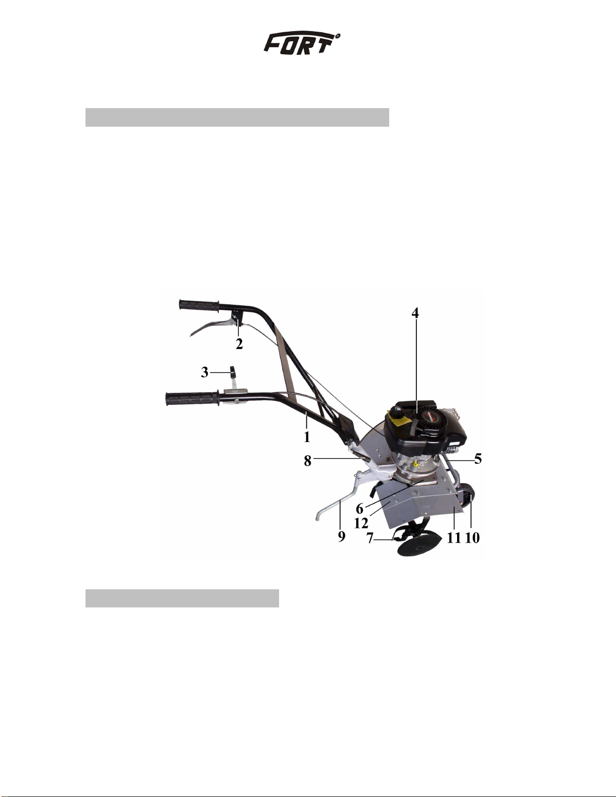
4. IDENTIFICATION OF COMPONENTS
1. HANDLE
2. CLUTCH LEVER
3. THROTTLE LEVER
4. ENGINE
5. TRANSFER HANDLE
6. GEARBOX CASE
7. MULCHERS WITH THE SIDE DISCS
8. CLAMPING LEVER FOR HANDLEBAR
9. BAR DRAG
10. WHEEL
11. EXTENDED FENDER
12. FENDER
PICTURE 1
5. CHECKS BEFORE USE
Before using the tiller you MUST assemble fenders. Tighten them with screws, washers and nuts
which are delivered with the tiller.
Check the following items before starting operation:
1. Make sure there is sufficient fuel to perform the work (see engine instructions)
2. Oil level in the reducer
3. Oil level in the engine (see engine instructions)
05
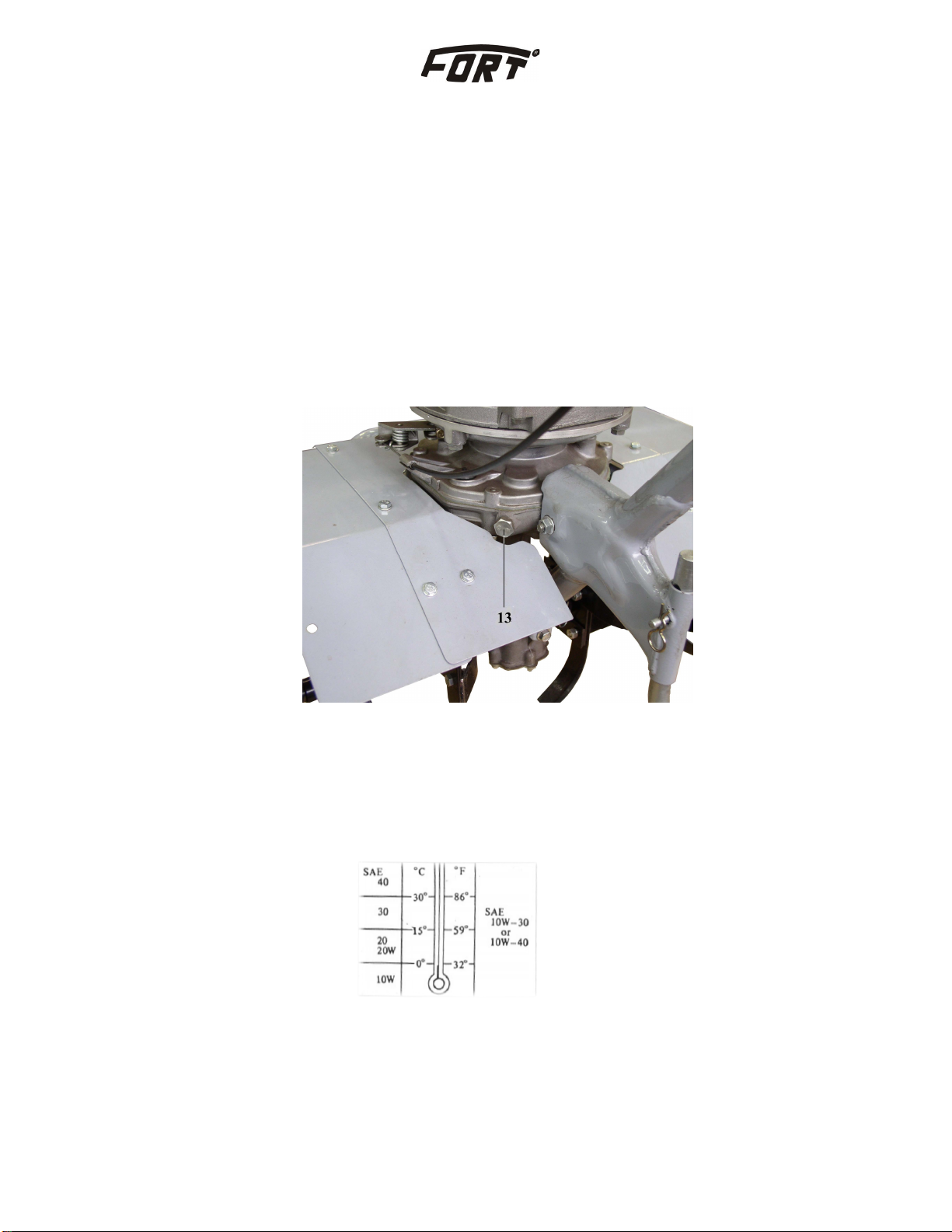
OIL LEVEL IN THE REDUCER
Lack of oil in the reducer will cause to much wearing and overheating. Heat is transmitted to the
engine case and that could cause damage of reducer and also the engine.
Make the following control, according to the picture 2:
-Flange should be in the horizontal position when you set the tiller. (lean the tillers forwards)
-Loosen the screw pos.13 (picture 2)
-Check if the oil level is up to screw hole
-If the oil level is low, refill the oil up to lower level of the screw hole
-Put back the screw pos. 13
PICTURE 2
LUBRICATION
For transmission lubrication, use the oil according to the table below. ( picture 3 ).
PICTURE 3
06
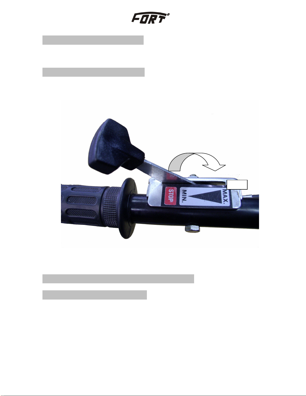
6. STARTING THE ENGINE
-When starting the engine, put the throttle lever to position “MAX” (picture 4).
7. STOPPING THE ENGINE (see engine instructions)
- When stopping the engine, put the throttle lever to position “STOP” (picture 4).
PICTURE 4
8. TILLER OPERATING INSTRUCTIONS
8.1Adjusting the handle position
Handle hight can be adjusted into three positions A, B and C depending on soil type and stature
of the operator. To adjust handle hight do the following according to picture 5.
1. Loosen the handle grip 8 and pull it for 1-1,5 cm, until the frame of the handlebar is free
pos. 1 ( picture 1 )
2. Rotate frame of the handlebar around it’s slot in inductor to required position with the
mild pressure to the inductor.
3. Tighten the handle grip of the handlebar 8 (picture 5).
MAX
07

PICTURE 5
8.2. Clutch adjusting
Clutch handle is anatomically shaped to suit, and not to tire, the operator during work. Clutch
puts mulchers to work, that is exit shaft. To engage the clutch squeeze the clutch lever next to the
handle bar. (picture 7).
When the clutch lever is released, work is disengaged and rotation of the exit shaft. (picture 6).
Do the clutch adjusting with the screw 14 and nut 15.
8
B
C
A
08

PICTURE 6
PICTURE 7
15
14
09

8.3. Transport wheel use
Use the transport wheel when transporting the power tiller, so the soil would not be damaged.
Like on picture 8, transport wheel is engaged and disengaged with very simple rotation around
the axis by protector 16 and bolt 17.
PICTURE 8
8.4. Using bar drag
Bar drag 9 (picture 1) is using in purpose creating of resistance of Power tiller movements .
It have possibilities of adjusting on 3 depth.. Usually the largest depth i.e. bottom position is
using for soft and mealy soil, and highest for hard soil.
10

To make adjustment please following instructions:
1. Plug out “beta” protector and bolt from inductor. Held handle bar with one arm.
2. When bar drag is free, with shift bar drag find appropriate bore for bolt
3. Bolt and beta protector return on there places.
WHEELS – delivered at the request
Onto exit shafts it’s possible to mount the wheels. Put the wheels on the exit shaft instead of
mulchers, and fix it with shaft and secure it with the wire protector.
We keep the right to change the information.
Not covered by guarantee:
-spark
-cable
-filters
-oil
11

FORT Srl Unipersonale - 36040 SOSSANO (Vicenza) Italia - Via Seccalegno, 29
Tel. (+39) 0444 788000 - Fax (+39) 0444 788020
Table of contents
Other Fort Tiller manuals


Popular Tiller manuals by other brands

Powerhorse
Powerhorse 41709 Operator's manual

Dirty Hand Tools
Dirty Hand Tools 103350 Operation manual

Weed Eater
Weed Eater WER500K owner's manual

Titan Implement
Titan Implement 2100 Series Operation and parts manual

Simplicity
Simplicity Snapper Operator's manual

Craftsman
Craftsman 917.299010 owner's manual


