manuals.online logo
Brands
  1. Home
  2. •
  3. Brands
  4. •
  5. Rinnai
  6. •
  7. Enclosure
  8. •
  9. Rinnai Smart Box SBOXI User manual

Rinnai Smart Box SBOXI User manual

Rinnai 1 SMART BOX IM
Smart Box® Installation Instructions
For Recess Enclosure SBOXI / SBOXC & Semi- Recess Frame SBOXF
To suit Rinnai REU water heater models: 1220 | 1620 | 2024 | 2426 | 2626 | 2630
Take care to AVOID exposing Smartbox
components to ANY EXCESSIVE HEAT when
welding pipes.
The Smart Box® (SBOX) Recess Enclosure
system is made up of two (2) components
these are the SBOXI (insert) and SBOXC
(cover). These are packed together in the one
carton.
If you DO NOT have a SBOXC (cover) for your
Smart Box contact your supplier.
SBOXC SBOXI
Cover
Clip
Slot
Cover
Clip
Slot
Cover
Clip
Slot Cover
Clip
Slot
Pipe
Access
Slot
Support
Bracket
Slot
DO NOT
Obstruct the slots provided for the Cover Clips, Support Bracket or Pipe Access
A
Securing the Smart
Box Insert externally
Securing the Smart
Box Insert internally
through the side wall
Securing the Smart
Box Insert internally
through the rear wall
Securing the Smart
Box Insert with the use
of brick ties
Securing Method B
Securing Method C
Securing Method D
Securing Method
Rinnai 2 SMART BOX IM
WARNING
The Smart Box and water heater MUST be installed in accordance with manufacturers instructions,
AS/NZS3000, AS/NZS3500 and AS/NZS5601. Local gas authorities may have additional local
requirements. As an example, some gas authorities require a minimum vertical clearance of 500mm or
more between the top of a gas meter and the air intake grille on the Smart Box Cover. Conrm all local
requirements prior to installation. Ensure any electrical wiring or plumbing pipework situated behind
the Smart Box are not damaged as a result of Smart Box installation.
SMART BOX® RECESS ENCLOSURE COMPONENTS
SBOXI (Insert) and SBOXC (Cover).
GENERAL PREPARATION
1. Prepare an opening in the wall approximately 1 metre above the ground.
The opening requirements are Height 1030 mm, Width 390 mm and a
minimum Depth of 160mm (see dimension diagrams page 3). Ensure the
location complies with the requirements of AS/NZS 5601 Fig. 6.2.
2. Remove the transport tab (1) from the pipe entry point of the Insert.
3. Determine the appropriate electrical access point and remove either the
left or right the knock out plug (2)located near the bottom of the side
walls of the Insert.
SECURING OPTIONS
The Smart Box Insert is designed to be surface mounted and may be
secured using one of the following methods:
(A) Securing the Smart Box Insert externally
Secure to the wall surface via the 8 screw holes provided in the ange of the
Insert using suitable fasteners.
(B) Securing the Smart Box Insert internally, through the side wall
Secure the Insert into a solid xture such as brickwork, timber studs etc,
through the side walls using suitable fasteners.
At least two fasteners should be used through each side wall approximately
125 mm from the inside top and bottom horizontal faces of the Insert.
NOTE
Excess space between the side walls of the Insert and the
solid xture may require packing to prevent distortion of the
Insert.
(C) Securing the Smart Box Insert internally, through the rear wall
Install two noggins (E) between wall studs (F), these are to be centred at
130 mm from the top and bottom of the opening. Secure the Insert into the
noggins (E) through the rear wall using suitable fasteners.
(D) Securing the Smart Box Insert with the use of a brick tie
Secure a brick tie to the side walls of the Insert with pop-rivets or screws.
As the brickwork is being laid use the attached brick ties to secure the Insert
into the brick courses. Use two brick ties per side, one near the top and
bottom of the Insert.
(G) Installing the Smart Box to rendered surfaces
Use spacers (G) (not provided) to install the Smart Box Insert, with su󰀩cient
clearance for rendering.
IMPORTANT
When the render is applied ensure that the gap provided by the stand-o󰀨 spacers is NOT exceeded as
this will prevent the Smart Box Cover from being tted!
Rinnai 3 SMART BOX IM
ASSEMBLY AND APPLIANCE INSTALLATION
CAUTION
The Smart Box Cover and Insert are constructed from durable ABS plastic. Nevertheless, take care
when welding any plumbing connections to ensure no Smart Box parts are subjected to a naked ame
or excessive heat. The Smart Box is NOT suitable for installation into walls which are required to be
‘re resisting’ as dened in the Building Code of Australia (BCA) unless alternative provisions are
made to achieve the required Fire Resistance Level (FRL). Refer to the BCA for more information.
1. The gas, cold water inlet and hot water outlet pipes can be brought through the pipe
entry point at the base of the Insert. The pipe entry point is elevated to prevent water
ingress. This can be sealed if required.
2. Remove the two M5 Nyloc nuts (3) from the xing studs (4) of the Insert.
IMPORTANT
Before installing the Rinnai water heater the serial and model numbers
on the data plate located on the left hand side of the appliance MUST
BE copied to the sticker on the inside of the Smart Box Cover. The serial
and model numbers are required for future service work.
3. sert the upper mounting bracket (5) of the Rinnai water heater into the bracket slot
(6) located at the top of the Insert.
Push the appliance up until the lower mounting bracket (7) aligns with the xing
studs (4) and secure in place with the two M5 Nyloc nuts (3) removed in step 5.
4. Connect the Rinnai water heater in accordance with the Operation / Installation
manual supplied with the water heater.
5. An approved weatherproof electrical GPO can be tted on either side inside the
Insert in accordance with AS/NZS 3000 Wiring Rules and other local requirements.
6. Commission and test the water heater in accordance with the Operation / Installation
manual supplied with the water heater.
Attach the warning sticker that is supplied with these instructions to the front Cover
of the Rinnai water heater.
7. Install the Smart Box Cover by aligning it with the Smart Box Insert (the ue spigot
hole is to be uppermost) and push into place ensuring that the 4 locking clips (8)
have engaged securely.
DIMENSIONS
Top View
Bottum View
Bottum View
Top View
B064616 4 SMART BOX II - IM - Issue 6 JUNE 2018
SMART BOX® SEMI-RECESS FRAME USE
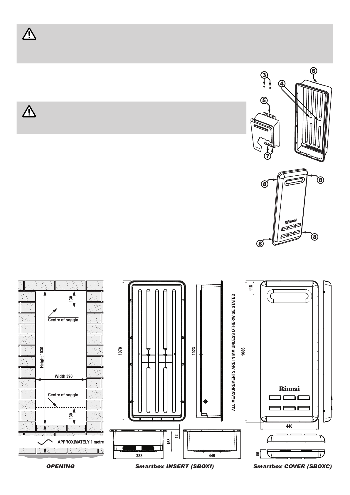
The SBOXF (Frame) is used when a semi-recessed installation of the
Smart Box recess enclosure is required. SBOXF reduces the cavity depth
requirements of the SBOXI (Insert) by 60mm. This is useful where the
depth of a wall cavity is insu󰀩cient to allow SBOXI to be fully recessed (for
example weatherboard or other non masonry walls).
NOTE
The Smart Box Frame (SBOXF) is to be installed at the same
time as the Smart Box Insert (SBOXI) and Smart Box Cover
(SBOXC).
These instructions are to be followed in conjunction with the
Installation Instructions for Insert and Cover supplied with
those items.
GENERAL PREPARATION
1. Prepare an opening in accordance with that which is specied in Step 1.
of General Preparation, on page 2.
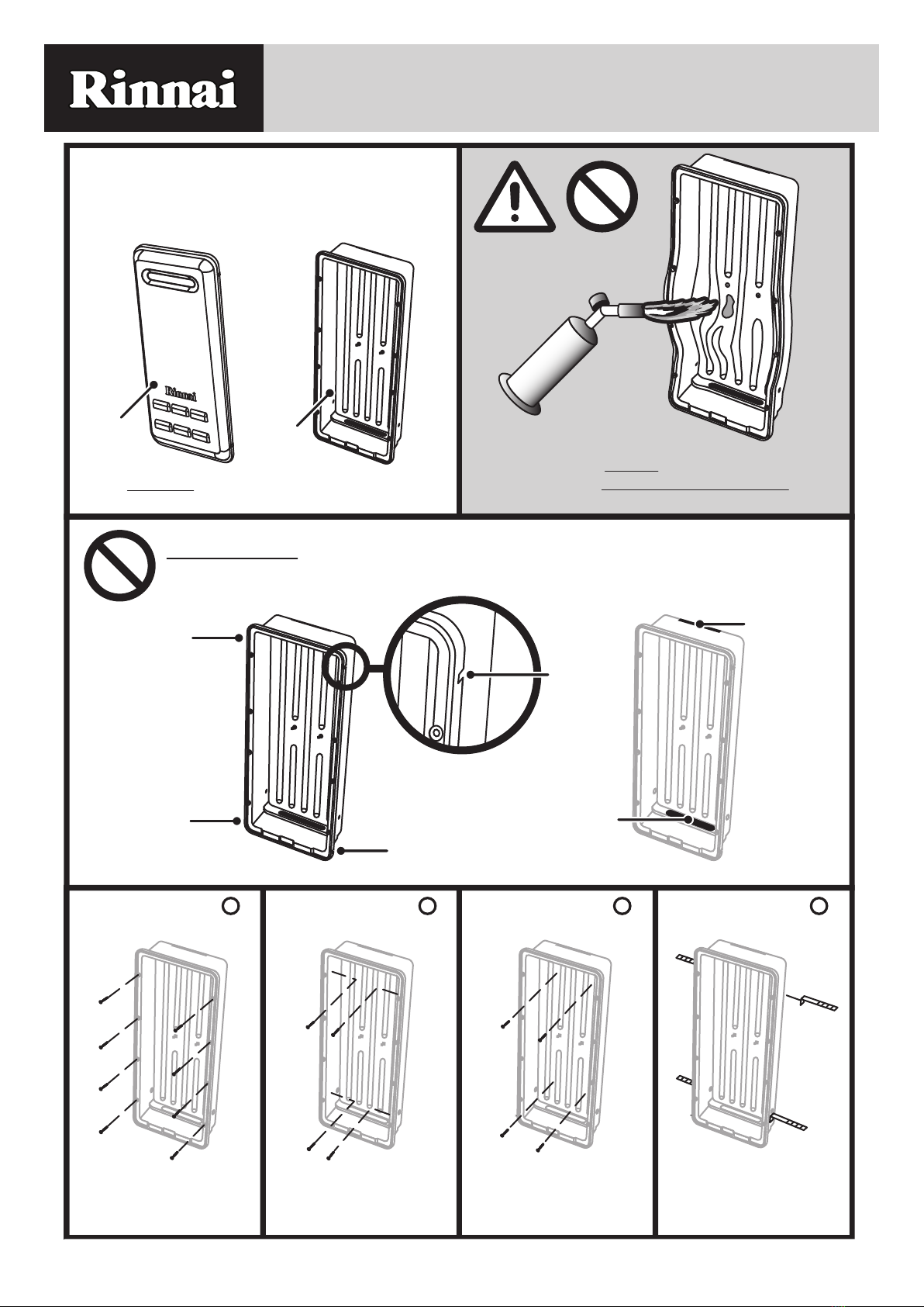
2. When installing the SBOXF (Frame) onto SBOXI (Insert) it should be
orientated so that the sealing ange (1) is against the wall surface and
the two drainage slots (2) are in the lower most position.
SECURING OPTIONS
The Smart Box Frame and Insert are designed for surface mounting and
may be secured using any of the methods described below:
(A) Securing SBOXI/SBOXF externally
Use the 8 x 100mm bugle screws (3) that are supplied with the SBOXF
(Frame) to secure both the SBOXF (Frame) and SBOXI (Insert) to the wall
surface.
IMPORTANT
When securing the SBOXI (Insert) and SBOXF (Frame) from
the front, use ONLY the 8 screw holes (3) that are provided.
DO NOT attempt to screw or nail through the sealing ange
of the SBOXF (Frame) as this may damage the Frame.
(B) Securing SBOXI/SBOXF internally through the side wall
Secure the SBOXI (insert) into a solid xture such as brickwork, timber studs
etc, through the side walls using suitable fasteners.
(C) Securing SBOXI/SBOXF internally through the rear wall
Install noggins between wall studs and secure through the rear wall of the
SBOXI (insert) using suitable fasteners.
(D) Securing SBOXI/SBOXF with the use of brick ties
Secure a brick tie to the side walls of the SBOXI (insert) with pop-rivets or
screws.
SBOXF
SBOXF
SBOXI
A
A
D
D
D
D
B
B
C
C
Rinnai has a Service and Spare Parts network with personnel who are fully trained and
equipped to give the best service on your Rinnai appliance. If your appliance requires
service, please call our National Help Line. Rinnai recommends that this appliance be
serviced at least every 2 years.
With our policy of continuous improvement, we reserve the right to change, or
discontinue at any time, specifications or designs without notice.
ABN 74 005 138 769
100 Atlantic Drive, Keysborough, Victoria 3173
P.O. Box 460, Braeside, Victoria 3195
AU45204
Australia Pty. Ltd.
Product Sales & Service National Help Line
Tel: 1300 555 545* Fax: 1300 555 655
*Monday to Friday, 8.00am to 5.30pm EST
For further information visit www.rinnai.com.au or email enquir[email protected]

This manual suits for next models

2

Other Rinnai Enclosure manuals

Rinnai INFINITY R1385 User manual

Rinnai

Rinnai INFINITY R1385 User manual

Rinnai INFINITY R1385G User manual

Rinnai

Rinnai INFINITY R1385G User manual

Rinnai Composite Recess Box User manual

Rinnai

Rinnai Composite Recess Box User manual

Rinnai Pipe Cover User manual

Rinnai

Rinnai Pipe Cover User manual

Rinnai RBOX06LW User manual

Rinnai

Rinnai RBOX06LW User manual

Popular Enclosure manuals by other brands

Synology DS-106 Series Quick installation guide

Synology

Synology DS-106 Series Quick installation guide

Focal Polyglass SB 33 V1 Specification sheet

Focal

Focal Polyglass SB 33 V1 Specification sheet

StarTech.com 8STS251BPU31C3 quick start guide

StarTech.com

StarTech.com 8STS251BPU31C3 quick start guide

ETI SOLID GSX quick start guide

ETI

ETI SOLID GSX quick start guide

Macally G-S350SU3 user manual

Macally

Macally G-S350SU3 user manual

Macally PHR-S250U3B user manual

Macally

Macally PHR-S250U3B user manual

CRU Dataport DE100 ATA 33 install guide

CRU Dataport

CRU Dataport DE100 ATA 33 install guide

ATX MAXNET MN5T installation manual

ATX

ATX MAXNET MN5T installation manual

ETI ECG42COM BO2/1-I Mounting instructions

ETI

ETI ECG42COM BO2/1-I Mounting instructions

Myers Power Products CTEG8-240MB Quick reference guide

Myers Power Products

Myers Power Products CTEG8-240MB Quick reference guide

UTC Fire and Security interlogix 60-928 installation instructions

UTC Fire and Security

UTC Fire and Security interlogix 60-928 installation instructions

Riotoro CR1080 user manual

Riotoro

Riotoro CR1080 user manual

Gembird EE3-U3S-3 user manual

Gembird

Gembird EE3-U3S-3 user manual

Dionex LC20 Operator's manual

Dionex

Dionex LC20 Operator's manual

Hamlet HXD3CCUU user manual

Hamlet

Hamlet HXD3CCUU user manual

schroff Interscale C user manual

schroff

schroff Interscale C user manual

extronics iSCAN301S operating manual

extronics

extronics iSCAN301S operating manual

Rocket Fish RF-PHD35 Guía del usuario

Rocket Fish

Rocket Fish RF-PHD35 Guía del usuario

manuals.online logo
manuals.online logoBrands
  • About & Mission
  • Contact us
  • Privacy Policy
  • Terms and Conditions

Copyright 2025 Manuals.Online. All Rights Reserved.