Rinnai ENERGYSAVER RHFE-308FTR User manual

Energysaver Co-axial Flue System
Installation Manual
For Models:
RHFE-308FTR
RHFE-309FT
RHFE-556FTR / FDT
RHFE-557FTR
RHFE-559FDT / FT
RHFE-561FT
RHFE-1004FDT / FT
RHFE-1005FDT / FT
USE ONLY RINNAI GENUINE PARTS

Before proceeding with an installation read this manual thoroughly and gain a full
understanding of the installation requirements, to ensure a safe and correct installation.
The Rinnai Energysaver® Co-Axial flue is certified as part of the Rinnai Energysaver space
heaters that have the designation ‘RHFE’ in the model number.
ONLY the Rinnai flue system components specified in this manual MUST be used.
Components NOT specified in this manual, whether manufactured by Rinnai or otherwise, are
NOT compatible and MUST NOT be used!
Rinnai appliance warranty conditions may be voided if non Rinnai flue components are fitted.
ONLY an authorised person must install, service and remove the Rinnai Energysaver® space
heater & flue system.
IMPORTANT
Rinnai Australia 2 ES Flue Installation Manual
CONVENTIONS USED IN THIS MANUAL . . . . . . . . . . . . . . . . . . . . . . . . . . . . . . . . . . . . . . . . . . . . . . . . . . . . . . . . 3
REGULATIONS, CLEARANCES & GENERAL INFORMATION . . . . . . . . . . . . . . . . . . . . . . . . . . . . . . . . . . . . . . . 4
FLUE TRANSITION CONNECTIONS . . . . . . . . . . . . . . . . . . . . . . . . . . . . . . . . . . . . . . . . . . . . . . . . . . . . . . . . . . . . . . . . . . . .5
LOCATION . . . . . . . . . . . . . . . . . . . . . . . . . . . . . . . . . . . . . . . . . . . . . . . . . . . . . . . . . . . . . . . . . . . . . . . . . . . . . . . . . . . . . . . . .5
LUBRICATING INNER PIPE COMPONENTS. . . . . . . . . . . . . . . . . . . . . . . . . . . . . . . . . . . . . . . . . . . . . . . . . . . . . . . . . . . . . .5
INSTALLATION CONFIGURATIONS . . . . . . . . . . . . . . . . . . . . . . . . . . . . . . . . . . . . . . . . . . . . . . . . . . . . . . . . . . . . 6
WALL PENETRATIONS . . . . . . . . . . . . . . . . . . . . . . . . . . . . . . . . . . . . . . . . . . . . . . . . . . . . . . . . . . . . . . . . . . . . . . 8
FLUE KIT COMPONENTS . . . . . . . . . . . . . . . . . . . . . . . . . . . . . . . . . . . . . . . . . . . . . . . . . . . . . . . . . . . . . . . . . . . 10
FLUE COMPONENT ASSEMBLY . . . . . . . . . . . . . . . . . . . . . . . . . . . . . . . . . . . . . . . . . . . . . . . . . . . . . . . . . . . . . 11
CREATING A “DIRECT” FLUE INSTALLATION . . . . . . . . . . . . . . . . . . . . . . . . . . . . . . . . . . . . . . . . . . . . . . . . . . . . . . . . . .11
CREATING A “DIRECT EXTENDED” FLUE INSTALLATION . . . . . . . . . . . . . . . . . . . . . . . . . . . . . . . . . . . . . . . . . . . . . . . .12
CREATING AN “EXTERNAL WALL” FLUE INSTALLATION . . . . . . . . . . . . . . . . . . . . . . . . . . . . . . . . . . . . . . . . . . . . . . . .13
CREATING A “SIDEWAYS” FLUE INSTALLATION . . . . . . . . . . . . . . . . . . . . . . . . . . . . . . . . . . . . . . . . . . . . . . . . . . . . . . .15
CREATING AN “UNDER FLOOR” FLUE INSTALLATION . . . . . . . . . . . . . . . . . . . . . . . . . . . . . . . . . . . . . . . . . . . . . . . . . .17
CUTTING ~ ESDFK, ESPIPE900 & ESROOFCOWL . . . . . . . . . . . . . . . . . . . . . . . . . . . . . . . . . . . . . . . . . . . . . . . . . . . . . . .19
COMPONENT ASSEMBLY & CONNECTION ~ ESPIPE900 . . . . . . . . . . . . . . . . . . . . . . . . . . . . . . . . . . . . . . . . . . . . . . . . .19
ASSEMBLING WALL TERMINAL ~ ESDFK & ESPIPE900. . . . . . . . . . . . . . . . . . . . . . . . . . . . . . . . . . . . . . . . . . . . . . . . . .20
ASSEMBLING AN ON-WALL TERMINAL ~ ESWTKIT, ESBEND & ESPIPE900 . . . . . . . . . . . . . . . . . . . . . . . . . . . . . . . . .20
COMPONENT ASSEMBLY & CONNECTION ~ ESBEND . . . . . . . . . . . . . . . . . . . . . . . . . . . . . . . . . . . . . . . . . . . . . . . . . . .21
COMPONENT ASSEMBLY & CONNECTION ~ ESCONDK. . . . . . . . . . . . . . . . . . . . . . . . . . . . . . . . . . . . . . . . . . . . . . . . . .21
COMPONENT ASSEMBLY & CONNECTION ~ ESROOFCOWL . . . . . . . . . . . . . . . . . . . . . . . . . . . . . . . . . . . . . . . . . . . . .21
CREATING AN “IN-WALL” FLUE INSTALLATION ~ ESFKIT03 & ESKITIW. . . . . . . . . . . . . . . . . . . . . . . . . . . . . . . . . . . .22
CONNECTING HEATER EXHAUST & AIR SUPPLY . . . . . . . . . . . . . . . . . . . . . . . . . . . . . . . . . . . . . . . . . . . . . . . 25
CONNECTING HEATER EXHAUST . . . . . . . . . . . . . . . . . . . . . . . . . . . . . . . . . . . . . . . . . . . . . . . . . . . . . . . . . . . . . . . . . . . .25
CONNECTING COMBUSTION AIR HOSE (AIR SUPPLY). . . . . . . . . . . . . . . . . . . . . . . . . . . . . . . . . . . . . . . . . . . . . . . . . . .26
CONNECTING CONDENSATE DRAIN TUBE TO HEATER . . . . . . . . . . . . . . . . . . . . . . . . . . . . . . . . . . . . . . . . . 27
CONTACT INFORMATION . . . . . . . . . . . . . . . . . . . . . . . . . . . . . . . . . . . . . . . . . . . . . . . . . . . . . . . . . . . . . . . . . . 28
TABLE OF CONTENTS

Rinnai Australia 3 ES Flue Installation Manual
CONVENTIONS USED IN THIS MANUAL
The following symbols are used to highlight specific requirements during installation steps.
CLEARANCES
Where required clearances will be provided and MUST be observed.
FALL
Ensure that the specified 2° fall is maintained to either the terminal or condensate trap.
MEASURE
Required measurements will be provided and MUST be observed for correct installation.
CUT
Cut as required to the specified measurements.
FINISH
Ensure that burrs and swarf are removed from all cut ends.
DISCARD
Denotes items that are not required for the specific installation.
OBSERVE CORRECT ORIENTATION
Where specified ensure that components are installed with the correct vertical or horizontal
orientation.
LUBRICATE
Use the supplied container of silicon grease to lubricate components. DO NOT use other
lubricants as these may damage the flue components.
SECURE
Where specified secure components with either installer provided or component supplied fixings.
DO NOT
Failure to observe DO NOT instructions will void the warranty of an appliance and may cause
injury or death.
NOTE / IMPORTANT
Important notes or general hints and guides provided to ease the installation.
CAUTION
Caution notes and or warnings that MUST be observed for safe and correct installations.
!
!

Rinnai Australia 4 ES Flue Installation Manual
REGULATIONS, CLEARANCES & GENERAL INFORMATION
The heater and the flue system shall be installed in accordance with the following:
These components MUST be installed, serviced and removed by an Authorised Person! ONLY the Rinnai flue
system components specified in this manual MUST be used. Componenents NOT specified in this manual,
whether manufactured by Rinnai or otherwise, are NOT compatible and MUST NOT be used!
Rinnai Energysaver space heater when correctly installed with Rinnai approved flue components are room-sealed
appliances and no internal ventilation is required. The Rinnai Energysaver space heater is fan-assisted. Therefore
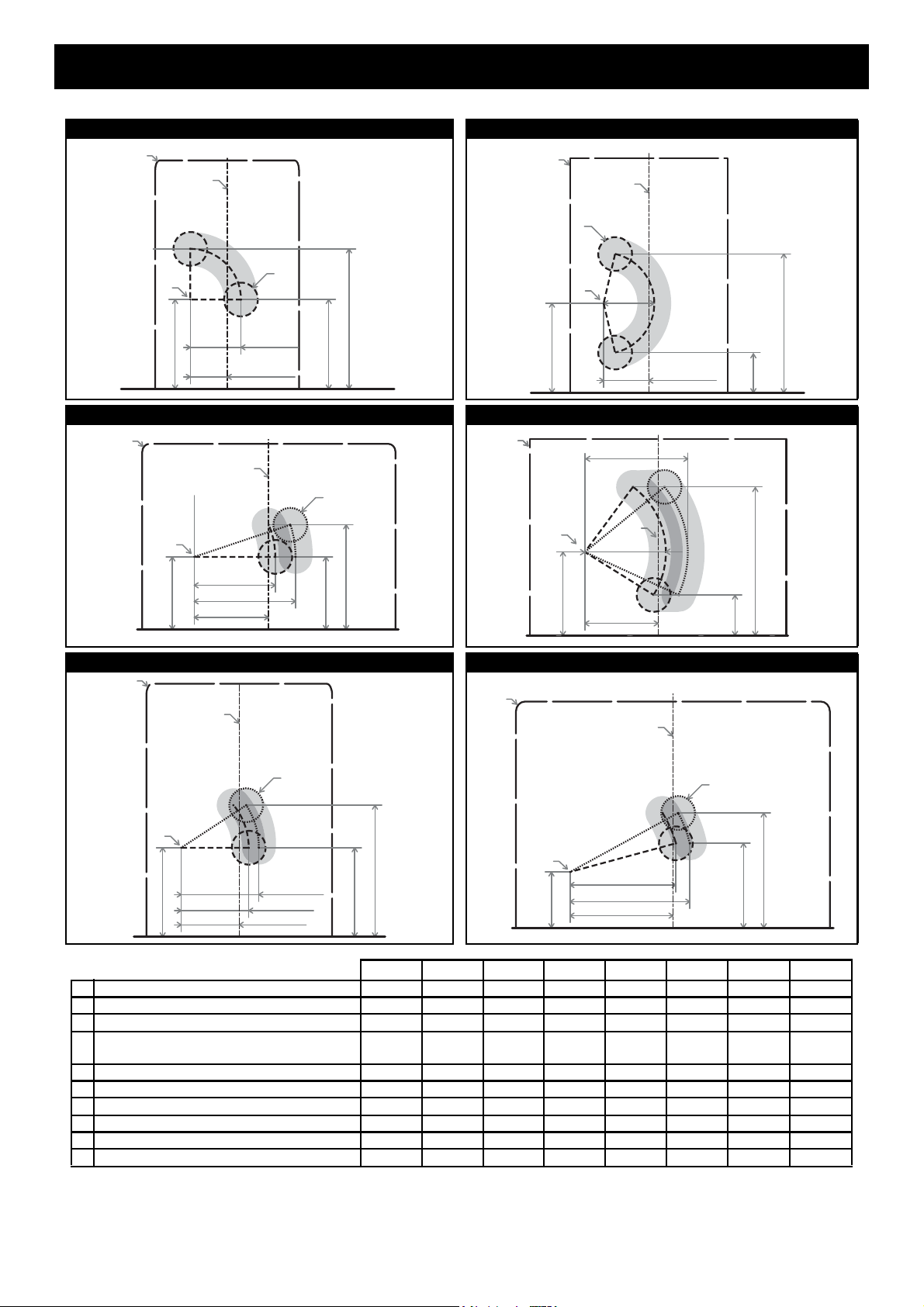
the fan assisted flue clearance dimensions from AS/NZS 5601 extract shown on this page MUST be used.
The outer plastic section of the Co-Axial Flue complies with temperature hazard requirements and can be installed
with zero clearance to combustible material. Vertical clearances when using a roof terminal (ESROOFCOWL) are
shown in Fig.1. If in doubt contact the Rinnai Australia National Helpline (number on the back page).
• Manufacturer’s Installation Instructions • Current AS/NZS 3000, AS/NZS 3500 & AS 5601
• Local Regulations and Municipal Building Codes • Any other relevant Statutory Regulation
Before commencing an installation, read the installation sections of the ‘Customer and
Installation Manual’ supplied with the heater.
Note that AS/NZS 5601 is referred to in this instruction and was current at the time of printing, but
may have since been superseded. It is the Installer’s responsibility to ensure that requirements
of the current version of AS/NZS 5601 are met.
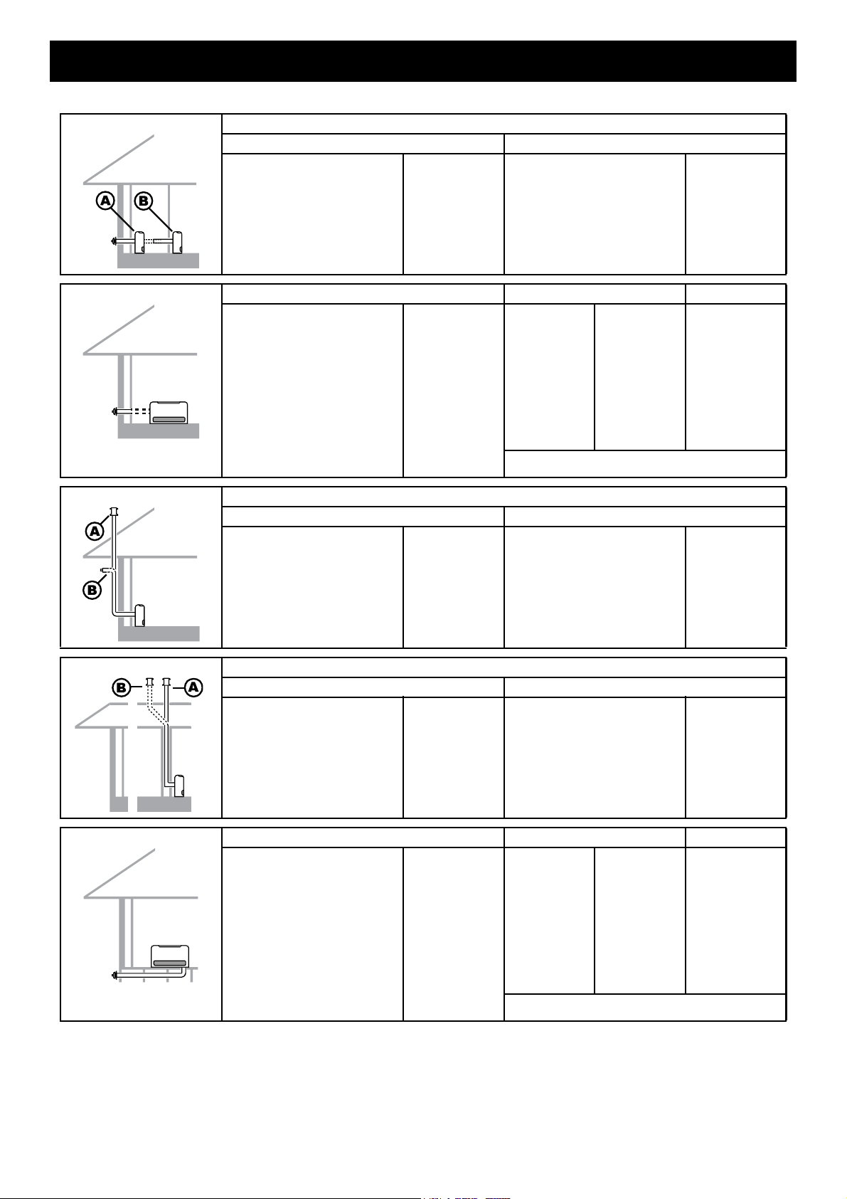
Horizontal Clearances (Extract AS/NZS 5601 Fig. 6.2)
Vertical Clearances Fig.1
IMPORTANT
Natural draft Fan assisted
Appliances
Appliances
b
meter regulator
meter
flue terminal
Appliances
Appliances
Appliances
Appliances
flue appliances
appliances
Appliances
Appliances
c, j k
2 flue terminal
3 flue terminal cylinder.
flue terminal
Ref. Item
Min. clearances (mm)
NOTES:
appliance certified
appliance s
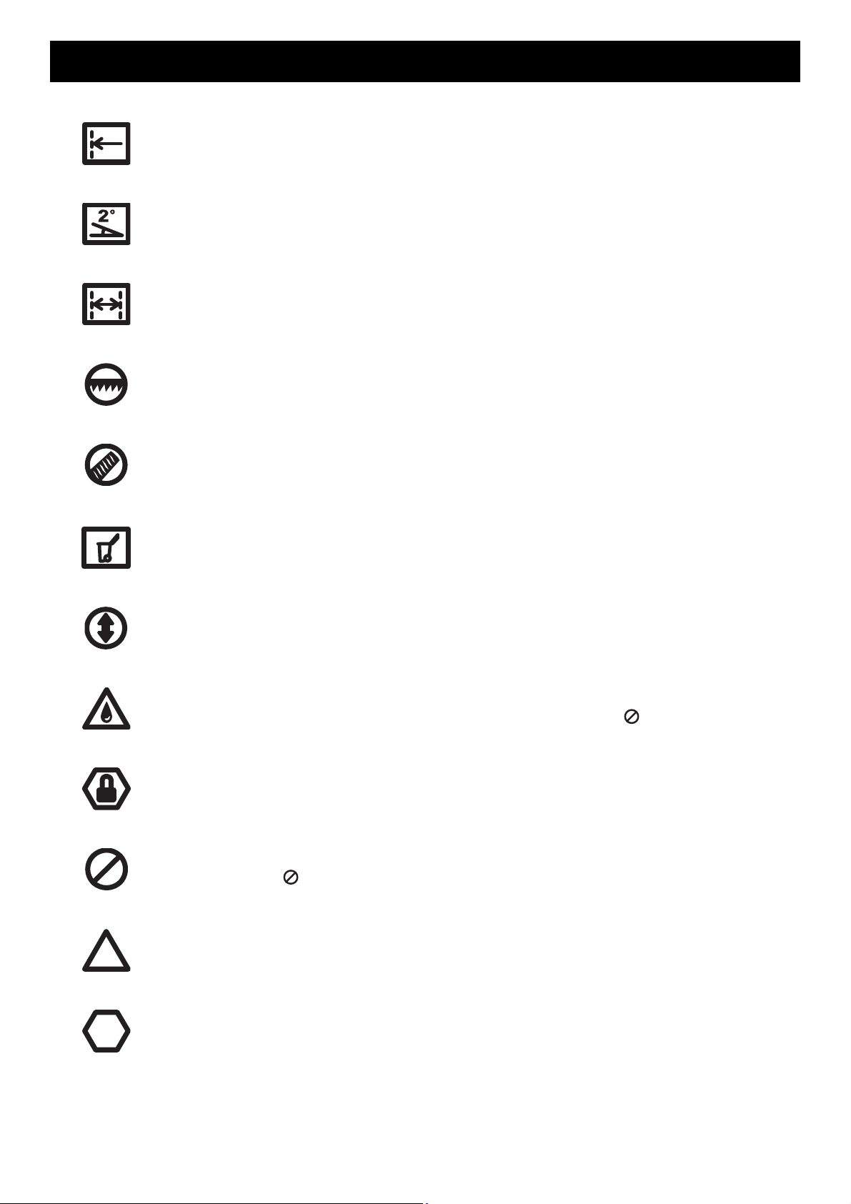
Flue terminal Fan assisted flue appliance only Gas meter Electricity meter or fuse box Mechanical air inlet
Minimum Clearance 500 mm
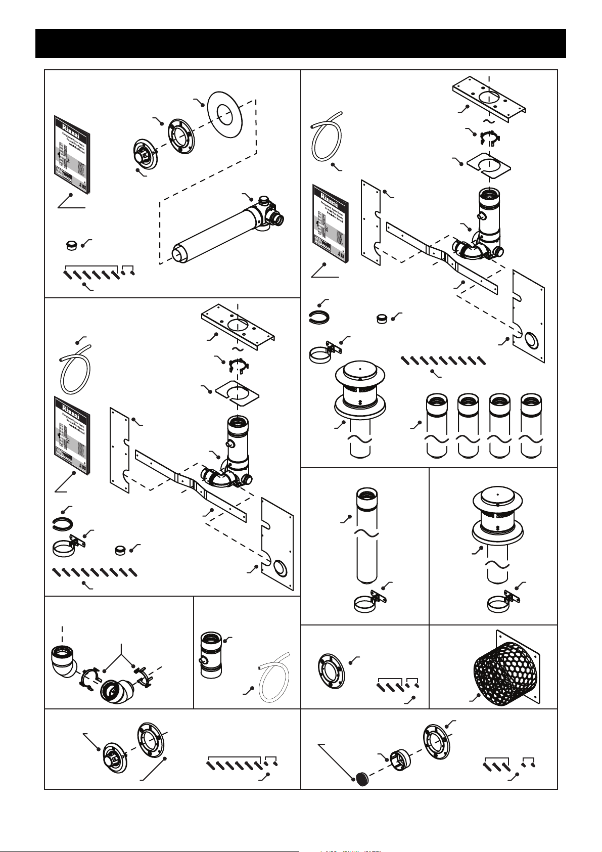
ESROOFCOWL
Decktite or lead collar flashing
ESPLATE
ESPIPE900
Flue pipe clip supplied withESPIPE900
Flue pipe clip supplied with ESROOFCOWL

Rinnai Australia 5 ES Flue Installation Manual
REGULATIONS, CLEARANCES & GENERAL INFORMATION
FLUE TRANSITION CONNECTIONS
Flue exhaust connection to heater. Combustion air inlet connection to heater (Right hand ~ Small connection
for models 308, 309, 556, 557, 559, 561 heaters. Left hand ~ Large connection for model 1004 & 1005 heaters).
Rubber combustion air inlet cap (when fitted) is designed to fit both the large and small combustion air inlet and
MUST cover the air inlet not in use. Combustion air inlet. Exhaust outlet.
LOCATION
LUBRICATING INNER PIPE COMPONENTS
The inner flue pipe joints are sealed with an “O” ring seal.
To help ensure a good seal and to ease assembly, a small tub of silicone grease is provided with the Direct Flue
Kit (ESDFK) and the In-Wall Transition Kit (ESKIT03). Use this silicone grease to lubricate the “O” ring on the inner
pipes prior to assembly.
This appliance is NOT suitable for inbuilt installations.
This appliance MUST NOT be installed where curtains or other combustible materials could come into contact
with it. In some cases curtains may need restraining.
Heat emanating from the front
of this appliance may over time
affect the appearance of some
materials used for flooring such
as carpet, vinyl, cork or timber.
This effect may be amplified if
the air in the room contains
cooking vapours or cigarette
smoke. To avoid this possibility,
it is recommended that a mat be
placed in front of the appliance,
extending at least 750mm in
front of it.
The flue terminal MUST BE positioned away from flammable materials.
In areas subject to heavy snowfall, keep snow clear of flue terminal at all times.
•DO NOT flue into natural
draught flues or fireplaces.
•DO NOT flue into other
rooms, roof spaces or into
under floor spaces.
•DO NOT Install the heater
in an unusually dusty area.
For other important information regarding the location of the heater refer to the instructions
supplied with the appliance.
Use ONLY the supplied silicone based “O” ring seal lubricant.
DO NOT use petroleum based lubricants such as petroleum jelly. Petroleum jelly or similar
petroleum based lubricants will cause deterioration of the “O” ring seals.
21
3
1
3
54
3
1
4
2
5
2
54
1
2
3
4
5
DO NOT
IMPORTANT
CAUTION

Rinnai Australia 6 ES Flue Installation Manual
INSTALLATION CONFIGURATIONS
The following configurations are currently available. For alternative configurations contact Rinnai.
DIRECT/EXTENDED Components
Option A (Direct) Option B (Direct Extended)
Direct Flue Kit ESDFK Direct Flue Kit
Co-Axial Pipe 900mm (Optional) #
ESDFK
ESPIPE900
SIDEWAYS Components Back Cover Kit Depth
Direct Flue Kit
Co-Axial Pipe 900mm #
Back Cover Kit
ESDFK
ESPIPE900
(refer page 10 for Kit
contents)
308
309
556
557
559
561
1004
1005
ESBSKA
ESBSKE
ESBSKB
ESBSKC
ESBSKF
ESBSKG
ESBSKD
ESBSKH
200 mm
205 mm
200 mm
200 mm
205 mm
200 mm
200 mm
205 mm
A Back Cover Kit is required when the flue system is installed
in a sideways configuration.
EXTERNAL WALL Components
Option A (Vertical Termination) Option B (On Wall Termination)
Direct Flue Kit
Co-Axial Pipe 900mm #
Bend (2 x 45º)
Condensate Trap
Roof Cowl
ESDFK
ESPIPE900
ESBEND
ESCONDK
ESROOFCOWL
Direct Flue Kit
Co-Axial Pipe 900mm #
Bend (2 x 45º)
Condensate Trap
Wall Terminal Kit
ESDFK
ESPIPE900
ESBEND
ESCONDK
ESWTKIT
IN-WALL Components
Option A (Direct) - ESFKITIW Option B (Offset) - ESFKITIW + ESBEND
In-Wall Adaption Kit §
Co-Axial Pipe 900mm x 4
Roof Cowl
ESKIT03
ESPIPE900
ESROOFCOWL
In-Wall Adaption Kit §
Co-Axial Pipe 900mm x 4
Bend (2 x 45º)
Roof Cowl
ESKIT03
ESPIPE900
ESBEND
ESROOFCOWL
UNDER FLOOR Components Back Cover Kit Depth
Direct Flue Kit
Co-Axial Pipe 900mm #
Bend (2 x 45º)
Wall Terminal Kit
Back Cover Kit
ESDFK
ESPIPE900
ESBEND
ESWTKIT
(refer page 10 for Kit
contents)
308
309
556
557
559
561
1004
1005
ESBSKA
ESBSKE
ESBSKB
ESBSKC
ESBSKF
ESBSKG
ESBSKD
ESBSKH
200 mm
205 mm
200 mm
200 mm
205 mm
200 mm
200 mm
205 mm
A Back Cover Kit is required when the flue system is installed
in a under floor configuration.
# Order lengths as required § Includes Condensate Trap (ESCONDK)

Rinnai Australia 7 ES Flue Installation Manual
INSTALLATION CONFIGURATIONS
• EXTERNAL WALL
• IN-WALL
• UNDER FLOOR
• SIDEWAYS
SIDEWAYS
IN-WALL
EXTERNAL WALL
UNDER FLOOR
DIRECT
• DIRECT
• DIRECT EXTENDED
Cut to correct
length & discard
DIRECT EXTENDED
Cut to correct
length & discard
Cut to correct
length & discard
A
A
A
See note 1.
Note 1. When cutting the flue transition for joining to other components the minimum total length is NOT to be less than 300mm!
Note 2. A Condensate trap MUST be used at this point.
Note 3. Use of a flue transition fitted with a sideways flue termal extension, will count as one of the THREE (3) allowed bends of a flue run.
Note 4. Where stipulated a Minimum 2° fall is required to ensure correct drainage of condensation formed in the discharge flue.
IMPORTANT
See Note 4.
Min 2° fall towards
the flue Terminal
!
See Note 4.
Min 2° fall towards
the flue Terminal
!
See Note 4.
Min 2° fall towards
the flue Terminal
!
See Note 4.
Min 2° fall towards
the flue Terminal
!
See Note 4.
Min 2° fall towards
the flue Terminal
!
See Note 4.
Min 2° fall towards
the appliance
!
Cut to correct
length & discard
!
See note 3.
!
See note 3.
!
See note 3.
!
See note 2.
!
See note 1.
!
See note 1.
!
See note 1.
!
See note 1.
!
See note 3.
!
See note 2.
!

Rinnai Australia 8 ES Flue Installation Manual
WALL PENETRATIONS
It is CRITICAL that any wall penetrations are located correctly.
Ensure there are no wall studs, noggins, wiring or other obstruction within the wall cavity where
the flue is proposed to penetrate.
Ensure the location of the flue terminal can comply with the requirements of AS/NZS 5601.
Figure 6.2 from AS/NZS 5601 and additional information is shown on page 4.
Especially relevant is the requirement to have a minimum of 300mm clearance between the flue
terminal and the finished ground level. It is NOT permissible to excavate a hole to obtain the
required 300mm clearance, unless there is sufficient drainage provision.
1. Select the desired location i for the Energysaver Heater.
2. Find the vertical centre line of the appliance ii and mark this
location on the wall.
3. Using Measurements A & B from Table 1, mark off the arc centre
iii on the wall.
The arc centre iii corresponds to the pivot point centre
of the telescopic flue elbow on the heater.
The RHFE-308 and RHFE-309 have a fixed length non-
telescopic flue elbow. Hence accurate marking of the
penetration arc and associated area are therefore
especially critical.
4. From the arc axis iii use the measurements C, D & E from Table
1. to draw an arc on the wall.
The lower end point of the arc iv will be the lower limit of the
minimum horizontal and vertical centre of penetration G.
The upper end point of the arc v will the be the upper limit of the
minimum horizontal and vertical centre of penetration G.
5. From the arc axis iii use the measurements F, D & E from Table
1. to draw an arc on the wall.
The lower end point of the arc vi will be the lower limit of the
maximum horizontal and vertical centre of penetration G.
The upper end point of the arc vii will be the upper limit of the
maximum horizontal and vertical centre of penetration G.
Due to the fixed length non-telescopic flue elbow of
the RHFE-308 and RHFE-309 model heaters
measurements C & F are the same for these models
only.
6. The penetration may be made anywhere within the confines of the
shaded minimum and maximum areas viii defined by the two
arcs.
CAUTION
B
A
iii
i
ii
IMPORTANT
G
D
E
C
iii iv
v
i
ii
D
E
F
iii vi
vii
G
i
ii
IMPORTANT
viii

Rinnai Australia 9 ES Flue Installation Manual
WALL PENETRATIONS
Below are diagrams and associated dimension tables for wall penetrations for each Energysaver heater model.
Table 1.
RHFE 308 RHFE 309
RHFE 556 RHFE 559
RHFE 557/561 RHFE 1004/1005
All dimension are in millimetres RHFE 308 RHFE 309 RHFE 556 RHFE 557 RHFE 561 RHFE 559 RHFE 1004 RHFE 1005
iWidth of appliance 426 465 750 550 545 760 930 930
ii Centre-Line of appliance 213 233 375 275 273 380 465 465
iii Arc axis (Axis point of the flue elbow) ——————— —
AHorizontal distance from Centre-Line to
arc centre
110 132 220 172 172 207 305 356
BVertical distance from base to arc centre 265 265 215 264 267 247 165 129
CMinimum horizontal limit of arc 150 150 240 200 200 240 325 376
DMinimum vertical limit of arc 265 120 215 264 267 120 250 250
EMaximum vertical limit of arc 415 410 310 390 393 440 340 340
FMaximum horizontal limit of arc 150 150 300 230 230 305 365 416
GPenetration diameter 100 100 100 100 100 100 100 100
D
B
E
A
i
ii
G
C & F
iii
i
C & F
iii
ii
B
D
E
A
G
D
B
E
A
C
F
G
ii
I
iii
A
iI
ii
C
F
D
E
B
iii
D
B
E
A
C
F
G
ii
i
iii
D
B
E
A
F
C
G
ii
i
iii

Rinnai Australia 10 ES Flue Installation Manual
FLUE KIT COMPONENTS
ESWFG
Flue Guard
ESDFK
(Direct Flue Kit)
Mounting/Securing Screws
Silicon Grease
Internal Wall Plate
External Wall Plate
Flue Terminal
7mm
x2
22mm
x6
Flue Transition
ESKIT03
(In-Wall Adaption Kit)
Vermin Plate Mounting/Securing Screws x9
Flue Transition /
Condensation Trap
Top Plate Bracket
Right Vermin Plate
Wall Spacer Plate
Left Vermin Plate
Mounting Strip
Silicon Grease
Wall Clip
Grommet (Use with 1004/1005)
Drain Tube
Pipe Locating Spacer
Flue Transition /
Condensation Trap
Top Plate Bracket
Right Vermin Plate
Wall Spacer Plate
Left Vermin Plate
Mounting Strip
Vermin Plate Mounting
/Securing Screws x9
Silicon Grease
Wall Clip
Grommet (Use with 1004/1005)
Drain Tube
Co-Ax
Vertical
Terminal
Co-Ax
Pipe x4
Pipe Locating Spacer
ESFKITIW
(Flue Kit In Wall)
ESWTKIT
(On-Wall Terminal Kit)
ESWTERM
Mounting/Securing Screws
7mm
x2
22mm
x6
Flue Terminal
External Wall Plate Mounting/Securing Screws
22mm
x3
7mm
x2
Pipe Spacer
External Wall Plate
Flue Outlet Grill
ESCONDK
(Condensate Trap Kit)
Condensation Trap
Drain Tube
ESPLATE
External Wall Plate
Mounting/Securing Screws
22mm
x3
7mm
x2
ESPIPE900
Co-Ax
Pipe
Wall
Clip
Co-Ax
Vertical
Terminal
ESROOFCOWL
Wall
Clip
This Manual
This Manual
This Manual
ESBEND
Co-ax Bends & Pipe Locating Spacer x2
BOTH spacers are required for all
offset and extended offset installations!

Rinnai Australia 11 ES Flue Installation Manual
FLUE COMPONENT ASSEMBLY
CREATING A “DIRECT” FLUE INSTALLATION
The Direct flue kit (ESDFK) is suitable for walls up to 385mm thick. ESDFK can be cut to length to suit wall
thicknesses less than 385mm thick. For wall thicknesses greater than 385mm Co-Axial Pipe(s) (ESPIPE900) can
be fastened onto ESDFK to extend the flue length. Refer to the section “CREATING A “DIRECT EXTENDED”
FLUE INSTALLATION” on page 12 for details.
Steps for creating a DIRECT flue installation are as follows:
1. Create the wall penetration(s) in accordance with the section “WALL PENETRATIONS” refer to page 8.
The minimum diameter required for wall the penetration for a DIRECT flue installation is 80mm to non
combustible surfaces such as brick and 100mm to combustible surfaces such as plaster.
Allow for a continuous 2° fall from the heater connection point to the wall terminal.
2. Slide the internal wall plate over the terminal end of the ESDFK pipe until it is nested on the raised ring of the
flue transition.
3. Pass the ESDFK through the internal wall penetration until the internal wall plate is flush with the wall.
4. Create the wall terminal in accordance with “ASSEMBLING WALL TERMINAL ~ ESDFK & ESPIPE900” refer
to page 20.
5. Make the heater exhaust and combustion air hose connections in accordance with the section “CONNECTING
HEATER EXHAUST & AIR SUPPLY” refer to page 25.
6. Install the correct back cover kit and fasten the heater and back cover kit to the internal wall surface.
7. Commission the heater in accordance with the manufacturer instructions supplied with the heater.
Activities for creating a Direct flue installation:
a. Locate Heater.
b. Create Wall Penetration.
c. Connect Heater Exhaust.
d. Connect Combustion Air Hose.
e. Installation and fastening of Back Cover Kit.
f. Cut Components (as required).
g. Assemble Wall Terminal.
z. Finalise Installation & Commissioning of Heater.
Air hose and heater exhaust connections at the Energysaver heater MUST be made and checked
in accordance with these instructions. Improper connections may result in dangerous situations,
for example, the dispersion of combustion products in the space being heated.
c
d
f
g
e z
b
a
CAUTION
CAUTION
2
Max’ wall thickness 385mm
Min’ required protrusion 15mm
Internal wall plate, outer face
1 3
Exterior wall
Interior wall
CAUTION

Rinnai Australia 12 ES Flue Installation Manual
FLUE COMPONENT ASSEMBLY
CREATING A “DIRECT EXTENDED” FLUE INSTALLATION
The Direct flue kit (ESDFK) is suitable for walls up to 385mm thick. For wall thicknesses greater than 385 mm
Co-Axial Pipe(s) (ESPIPE900) can be fastened onto ESDFK to extend the flue length.
Steps for creating a Direct Extended flue installation are as follows:
1. Create the wall penetration(s) in accordance with the section “WALL PENETRATIONS” on page 8.
The minimum diameter required for wall the penetration for a DIRECT flue installation is 80mm to
noncombustible surfaces such as brick and 100mm to combustible surfaces such as plaster.
Allow for a continuous 2° fall from the heater connection point to the wall terminal.
2. Join ESPIPE900 to ESDFK. Fit additional lengths of ESPIPE900 as required.
Slide the internal wall plate over the terminal end of the assembled flue pipe until it is nested on the raised ring
of the flue transition.
3. Pass the flue assembly through the internal wall penetration until the internal wall plate is flush with the wall.
4. Create the wall terminal in accordance with “ASSEMBLING WALL TERMINAL ~ ESDFK & ESPIPE900” refer
to page 20.
5. Make the heater exhaust and combustion air hose connections in accordance with the section “CONNECTING
HEATER EXHAUST & AIR SUPPLY” refer to page 25.
6. Install the back cover kit and fasten the Energysaver heater and back cover kit to the internal wall surface.
7. Commission the heater in accordance with the manufacturer instructions supplied with the heater.
Activities for creating a Direct Extended flue installation:
a. Locate of Heater.
b. Create Wall Penetration.
c. Connect Heater Exhaust.
d. Connect Combustion Air Hose.
e. Installation and fastening of Back Cover Kit.
f. Cut, Fit & Secure Components (as required).
g. Assemble Wall Terminal.
z. Finalise Installation & Commissioning of Heater.
The joints between ESDFK and ESPIPE900 and any additional ESPIPE900 lengths MUST be
secured by a pop rivet or screw through the outer Co-Axial pipes to prevent accidental or
erroneous dislodgement. ESDFK and ESPIPE900 DO NOT require cutting to be joined.
Cutting of components is not required for the purposes of joining and ESPIPE900 to ESDFK or
other ESPIPE900.
Air hose and heater exhaust connections at the Energysaver heater MUST be made and checked
in accordance with these instructions. Improper connections may result in dangerous situations,
for example, the dispersion of combustion products in the space being heated.
z
c
d
a
e
g
f
b
Total flue length can be up
to nine (9) metres long!
Total flue length can be
up to nine (9) metres long!
CAUTION
CAUTION
CAUTION
1 2
Internal wall plate, outer face
3
Exterior wall
Interior wall
Min’ required protrusion 50mm
CAUTION
CAUTION
CAUTION

Rinnai Australia 13 ES Flue Installation Manual
FLUE COMPONENT ASSEMBLY
CREATING AN “EXTERNAL WALL” FLUE INSTALLATION
The creation of the horizontal section of flue installation is the same as creating a DIRECT or DIRECT EXTENDED
flue installations with the following exceptions:
The direction of horizontal fall of the flue pipe is reversed. For Wall External flue installations, a 2° fall is
required from the wall penetration towards the heater. This will ensure the small amount of condensation in the
short section between the heater and condensation trap will ‘burn off’ rapidly during normal operation.
An ESBEND rather than a mushroom flue terminal is fitted at the end of the horizontal flue run.
Steps for creating a External-Wall flue installation are as follows:
1. Create the wall penetration(s) in accordance with the section “WALL PENETRATIONS” refer to page 8.
The minimum diameter required for wall the penetration for a DIRECT flue installation is 80mm
noncombustible surfaces such as brick and 100mm to combustible surfaces such as plaster.
Allow for a continuous 2° fall towards the heater connection point from the external wall penetration.
2. Prepare the 'horizontal' section by following step 2 of “CREATING A “DIRECT” FLUE INSTALLATION” refer to
page 11 or step 2 of “CREATING A “DIRECT EXTENDED” FLUE INSTALLATION” refer to page 12 depending
on wall thickness (note that a direct extended flue installation example is illustrated above).
Slide the internal wall plate over the terminal end of the assembled flue pipe until it is nested on the raised ring
of the flue transition.
3. Pass the flue assembly through the internal wall penetration until the internal wall plate is flush with the wall.
Activities for creating an External Wall installation:
a.- f. Refer to Direct & Direct Extended (as required).
g. Assemble Wall Plate.
h. Assemble & Fit Bend.
i. Fit Condensate Drain.
j. Cut, Fit & Secure Components. Seal Joints
(as required).
k. Create Vertical Penetrations (as required).
l. Fit & Fasten Roof Cowl or On-Wall Terminal.
z. Finalise Installation & Commissioning of Heater.
Sections of flue installation located outside require the following precautions:
ONLY use PVC cement between joints of the 'outer' PVC flue pipes to secure and seal these
joints against ingress of dust and water.
ONLY use non acidic silicone sealant between the joints of 'outer' PVC flue pipes and any
mating aluminium components (such as the condensate trap) to secure and seal these joints
against ingress of dust and water. Silicone containing acetic acid (vinegar) or other acids as the
curing agent may cause corrosion of aluminium components and MUST NOT be used.
Total flue length can be up
to nine (9) metres long and
can contain a maximum of
three (3) ESBEND (3 x 90°)!
a - f
i
j
g
h
k
l
z
CAUTION
CAUTION
Min’ required protrusion 50mm
Internal wall plate, outer face
3
Exterior wall
Interior wall
1 2

Rinnai Australia 14 ES Flue Installation Manual
FLUE COMPONENT ASSEMBLY
4. Slide the external wall plate over the outer pipe protruding through the exterior wall. Align the arrow
symbol to point downwards which will result in a 2° fall of the horizontal section of flue pipe towards the
appliance as required.
Once the external wall plate is in the correct position secure it to the wall using the three 22mm screws
into the holes provided. The wall plate is then secured to the outer pipe of the flue protrusion using the
two horizontal holes and the two 7mm screws provided.
5. Cut the flue pipe end protruding through the exterior wall in accordance with “CUTTING ~ ESDFK,
ESPIPE900 & ESROOFCOWL” refer to page 19.
6. Now prepare the vertical section of the flue system by assembling, connecting and securing ESBEND,
ESCONDK and subsequent ESPIPE900 lengths as required in accordance with the relevant sections under
“COMPONENT ASSEMBLY & CONNECTION ~ ESBEND” refer to page 20, “COMPONENT ASSEMBLY &
CONNECTION ~ ESCONDK” refer to page 20 and “COMPONENT ASSEMBLY & CONNECTION ~
ESPIPE900” refer to page 19.
7. If a vertical roof terminal is used cut in accordance with “CUTTING ~ ESDFK, ESPIPE900 & ESROOFCOWL”
refer to page 19 and assemble and connect in accordance with “COMPONENT ASSEMBLY & CONNECTION
~ ESROOFCOWL” refer to page 21.
If a horizontal terminal is used cut in accordance with “CUTTING ~ ESDFK, ESPIPE900 & ESROOFCOWL”
refer to page 19 and assemble and connect in accordance with “ASSEMBLING AN ON-WALL TERMINAL ~
ESWTKIT, ESBEND & ESPIPE900” refer to page 20.
8. Make the heater exhaust and combustion air hose connections in accordance with the section “CONNECTING
HEATER EXHAUST & AIR SUPPLY” refer to page 25.
9. Install the back cover kits and fasten the heater and back cover kit to the internal wall surface.
10. Commission the heater in accordance with the manufacturer instructions supplied with the heater.
The joints between ESDFK and ESPIPE900 and any additional ESPIPE900 lengths MUST be
secured by a pop rivet or screw through the outer Co-Axial pipes to prevent accidental or
erroneous dislodgement. ESDFK and ESPIPE900 DO NOT require cutting to be joined.
ONLY use PVC cement between joints of the 'outer' PVC flue pipes to secure and seal these
joints against ingress of dust and water.
ONLY use non acidic silicone sealant between the joints of 'outer' PVC flue pipes and any
mating aluminium components (such as the condensate trap) to secure and seal these joints
against ingress of dust and water. Silicone containing acetic acid (vinegar) or other acids as the
curing agent may cause corrosion of aluminium components and MUST NOT be used.
Secure the vertical flue sections to the wall using the clips provided to prevent accidental
dislodgement.
Air hose and heater exhaust connections at the Energysaver heater MUST be made and checked
in accordance with these instructions. Improper connections may result in dangerous situations,
for example, the dispersion of combustion products in the space being heated.
4 65
Min’ required protrusion 50mm
!
7mm x 2
22mm x 3
!
!
CAUTION
CAUTION
CAUTION

Rinnai Australia 15 ES Flue Installation Manual
FLUE COMPONENT ASSEMBLY
CREATING A “SIDEWAYS” FLUE INSTALLATION
The Sideways flue installation can run along the left or right hand side of the internal wall behind the heater.
Steps for creating a Sideways flue installation are as follows:
1. Using a drill, remove the pop rivet used to fasten the straight flue pipe connection pipe to the flue transition of
ESDFK and remove but DO NOT discard the straight flue pipe connection.
2. Fit the elbowed flue pipe connection supplied with the Back Cover kit to the flue transition pushing it fully home
and then fasten in place with the grub screw (supplied) using an Allen key. The grub screw terminates in a
groove in the flue transition. When fastened this prevents accidental dislodgement of the pipe connections.
3. Refit the straight flue pipe connection to the end of the elbow until it is fully home and then fasten in place with
a 3mm rivet.
4. Temporarily position the heater in the desired position.
5. Attach ESDFK to the flue outlet pipe from the rear of the heater. Align the flue in an almost horizontal manner
in the desired direction of discharge (either left of right) with a 2° fall towards the flue terminal.
Activities for creating a Sideways flue installation:
a. Modify ESDFK for Sideways Installation.
b. Create Penetration in Side Panel. *
c. Locate Heater.
d. Connect Heater Exhaust.
e. Connect Combustion Air Hose.
f. Installation and fastening of Back Cover Kit
(ESBSK).
g. Cut, Fit & Secure Components (as required).
y. Refer to steps f & g of Direct & Direct Extended
(as required).
z. Finalise Installation & Commissioning of Heater.
* Create penetration only in side panel associated
with the direction of the horizontal flue run.
Most components in a sideways flue installation are located indoors and may be in an
accessible position after installation. To prevent accidental or erroneous dislodgement, the joints
between ESDFK and ESPIPE900 components MUST be secured by pop rivet or screw through
the outer Co-Axial pipes and flue pipes are to be clipped to the wall using the stand off clips
supplied or other suitable method.
Ensure the straight pipe and elbow are securely fastened to the flue transition by the grub
screw and rivets. Test soundness of the connections by attempting to 'pull apart' the assembled
components. Improper assembly or fastening can result in products of combustion dispersing
into the room being heated which may result in a dangerous condition.
Ensure the flue components are positioned to have a minimum 25mm clearance from any
sensor wires at the rear of the heater.
c
f
g
a
d
b
b
e
y
Total flue length can be up
to nine (9) metres long and
can contain a maximum of
two (2) ESBEND (2 x 90°)!
CAUTION
CAUTION
CAUTION
CAUTION
1 2 3
GRUB
SCREW
(Supplied)
3mm RIVET
CAUTION
CAUTION

Rinnai Australia 16 ES Flue Installation Manual
FLUE COMPONENT ASSEMBLY
6. Attach the appropriate side spacer panel from the back cover kit (ESBSK A, B, C, D, E, F, G or H) to the rear
of the heater in accordance with the assembly Instructions supplied with the back cover kit.
7. Mark the location of the flue penetration through the side spacer panel.
8. Remove the side cover panel and cut or knock out an 85mm Ø hole for the flue pipe to pass through. Ensure
the hole edges are smooth.
9. Fit the protective plastic edge supplied with the back cover kit around the circumference of the hole in the side
spacer panel.
10. Fit a length of ESPIPE900 to ESDFK in accordance with “COMPONENT ASSEMBLY & CONNECTION ~
ESPIPE900” refer to page 19.
11. Re-attach the side spacer panel to the heater with the flue pipe passing through it.
12. Locate the heater in the desired position relative to the wall. DO NOT secure the heater at this stage.
13. Fit additional lengths of ESPIPE900 as required.
14. Create the wall penetration(s) in accordance with the section “WALL PENETRATIONS” refer to page 8.
The minimum diameter required for wall the penetration for ESPIPE900 is 80mm.
Allow for a continuous 2° fall from the heater connection point from to the wall penetration.
15. Slide the internal wall plate supplied with ESDFK over the length of ESPIPE900 penetrating the wall at the
internal wall end. Then pass the assembly through the internal wall penetration.
16. Fasten the internal wall plate to the internal wall.
17. Create the wall terminal in accordance with “ASSEMBLING WALL TERMINAL ~ ESDFK & ESPIPE900” refer
to page 20. Make the heater exhaust and combustion air hose connections in accordance with the section
“CONNECTING HEATER EXHAUST & AIR SUPPLY” refer to page 23.
18. Install the remaining parts of the back cover kit and fasten the heater and back cover kit to the internal wall
surface.
19. Commission the heater in accordance with the manufacturer instructions supplied with the heater.
The joint between ESDFK and ESPIPE900 MUST be secured by a pop rivet or screw through
the outer Co-Axial pipes and flue pipes are to be clipped to the wall using the stand off clips
supplied or other suitable method. ESDFK and ESPIPE900 DO NOT require cutting to be joined.
The joints between ESPIPE900 lengths MUST be secured by a pop rivet or screw through the
outer Co-Axial pipes and flue pipes are to be clipped to the wall using the stand off clips supplied
or other suitable method. ESDFK and ESPIPE900 DO NOT require cutting to be joined.
Air hose and heater exhaust connections at the heater MUST be made and checked in
accordance with these instructions. Improper connections may result in dangerous situations,
for example, the dispersion of combustion products in the space being heated.
CAUTION
CAUTION
14
Internal wall plate
16
Interior wall
15
Interior wall
Interior wall
CAUTION

Rinnai Australia 17 ES Flue Installation Manual
FLUE COMPONENT ASSEMBLY
CREATING AN “UNDER FLOOR” FLUE INSTALLATION
The Down and Out flue option allows for a Direct Flue Kit (ESDFK) to face downwards and the flue to be run
vertically though a hole in the floor, and then horizontally to a suitable location outside.
Steps for creating a Under Floor flue installation are as follows:
1. Using a drill, remove the pop rivet used to fasten the straight flue pipe connection pipe to the flue transition of
ESDFK and remove but DO NOT discard the straight flue pipe connection.
2. Fit the elbowed flue pipe connection supplied with the back cover kit to the flue transition pushing it fully home
and then fasten in place with the grub screw (supplied) using an Allen key. The grub screw terminates in a
groove in the flue transition. When fastened this prevents accidental dislodgement of the pipe connections.
3. Refit the straight flue pipe connection to the end of the elbow until it is fully home and then fasten in place with
a 3mm rivet.
4. Attach the side cover panels from the back cover kit (ESBSK A, B, C, D, E, F, G or H) to the rear of the heater
in accordance with the assembly Instructions supplied with the back cover kit and temporarily position the
heater in the desired position.
Check proposed route of down and out flue to confirm there are no obstructions in the flue path.
5. Temporarily attach ESDFK to the flue outlet pipe from the rear of the heater. Align the flue in a vertical manner.
Activities for creating a Under Floor flue installation:
a. Modify ESDFK for Under Floor Installation.
b. Create Penetration in floor.
c. Install side panels of Back Cover Kit (ESBSK).
d. Locate Heater.
e. Connect Heater Exhaust.
f. Connect Combustion Air Hose.
g. Installation and fastening of Back Cover Kit
(ESBSK).
h. Cut, Fit & Secure Components (as required).
y. Refer to steps f & g of Direct & Direct Extended (as
required).
z. Finalise Installation & Commissioning of Heater.
Flue MUST NOT terminate under a building.
Flue terminal is ONLY available in the horizontal format.
Ensure the straight pipe and elbow are securely fastened to the flue transition by the grub
screw and rivets. Test soundness of the connections by attempting to 'pull apart' the assembled
components. Improper assembly or fastening can result in products of combustion dispersing
into the room being heated which may result in a dangerous condition.
Ensure the flue components are positioned to have a minimum 25mm clearance from any
sensor wires at the rear of the heater.
c
e
a
b
h
f
g
d
y
Total flue length can be up
to nine (9) metres long and
can contain a maximum of
two (2) ESBEND (2 x 90°)!
CAUTION
CAUTION
CAUTION
CAUTION
1 2 3
GRUB
SCREW
(Supplied)
3mm RIVET
CAUTION
CAUTION

Rinnai Australia 18 ES Flue Installation Manual
FLUE COMPONENT ASSEMBLY
6. Mark the location of the flue floor penetration, then cut an 100mm Ø hole through the floor. Ensure
the hole edges are smooth.
7. Disconnect ESDFK form the heater. Pass ESDFK through both a stand off clip and the internal wall plate, then
pass the assembly through the floor penetration.
8. Secure ESDFK to the wall with a the stand off clip and fasten the internal wall plate in place to the floor.
9. Prepare the horizontal section of the flue system located under floor by assembling connecting and securing
ESPIPE900, ESBEND and subsequent ESPIPE900 lengths as required in accordance with the relevant
sections under “COMPONENT ASSEMBLY & CONNECTION ~ ESBEND” refer to page 20 and
“COMPONENT ASSEMBLY & CONNECTION ~ ESPIPE900” refer to page 19.
10. Locate the heater in the desired position relative to the wall. DO NOT secure the heater at this stage.
11. If required create a wall penetration(s) in accordance with the section “WALL PENETRATIONS” refer to page 8.
The minimum diameter required for wall the penetration for ESPIPE900 is 80mm.
Allow for a continuous 2° fall from the heater connection point to the wall penetration.
12. Create the wall terminal in accordance with “ASSEMBLING WALL TERMINAL ~ ESDFK & ESPIPE900” refer
to page 20.
13. Make the heater exhaust and combustion air hose connections in accordance with the section “CONNECTING
HEATER EXHAUST & AIR SUPPLY” refer to page 25.
14. Install the remaining parts of the back cover kit and fasten the heater and back cover kit to the internal wall
surface.
15. Commission the heater in accordance with the manufacturer instructions supplied with the heater.
Joints between ESDFK, and ESPIPE900 MUST be secured by a pop rivet or screw through the
outer Co-Axial pipes to prevent accidental or erroneous dislodgement. Pipes are to be clipped
using the stand off clips supplied or other suitable method. ESDFK and ESPIPE900 DO NOT
require cutting to be joined.
Of special relevance to under floor installations is the requirement to have a minimum of 300mm
clearance between the flue terminal and the finished ground level. It is NOT permissible to
excavate a hole to obtain the required 300mm clearance, unless there is sufficient drainage
provision.
Air hose and heater exhaust connections at the heater MUST be made and checked in
accordance with these instructions. Improper connections may result in dangerous situations,
for example, the dispersion of combustion products in the space being heated.
6 8
Interior wall
7
Interior wall
Interior wall
Internal wall plateInternal wall plate
Floor Penetration
location
In
Stand off clip
CAUTION
CAUTION
CAUTION

Rinnai Australia 19 ES Flue Installation Manual
FLUE COMPONENT ASSEMBLY
CUTTING ~ ESDFK, ESPIPE900 & ESROOFCOWL
Cutting components to achieve a desired length
1. Measure and mark off the outer pipe at the desired length (AA).
2. Cut the outer pipe to the required length. Take care NOT to cut the inner pipe.
3. From the ‘new’ end of the outer pipe (cut in Step 2.), measure and mark off an additional 12mm on the inner
pipe (BB). Cut the inner pipe at this mark. Take care to keep the cut parallel with that of the outer pipe.
4. Ensure all burrs and swarf are removed from all cut ends.
Cutting components at a wall penetration
1. Measure and mark off the outer pipe at a point flush with the surface of the wall penetrated (CC) PLUS an
additional 50mm (DD).
2. Cut the outer pipe to the required length. Take care NOT to cut the inner pipe.
3. From the ‘new’ end of the outer pipe (cut in Step 2.), measure and mark off an additional 12mm on the inner
pipe (EE). Cut the inner pipe at this mark. Take care to keep the cut parallel with that of the outer pipe.
4. Ensure all burrs and swarf are removed from all cut ends.
COMPONENT ASSEMBLY & CONNECTION ~ ESPIPE900
Lubricate O-Rings with the supplied O-ring grease, then fit the female aluminium inner pipe end over the male
inner pipe ends of an adjoining component.
STOP! When terminating a flue run and installing the wall terminal, follow the instructions under
“ASSEMBLING WALL TERMINAL ~ ESDFK & ESPIPE900” on page 20 for pipe cutting procedures.
Cutting is not required for the purposes of joining ESDFK, ESPIPE900 & ESROOFCOWL together
Cutting of the last component in the flue assembly (the component furthest away from the heater)
may be required to achieve the required flue system length. Cutting is also required at a wall
penetration. Cutting for both purposes is described below:
The minimum length (ZZ) of ESDFK when measured from the back plate of the casting MUST
NOT be less than 300mm when joining to other components.
The minimum length (ZZ) of ESDFK when measured from the back plate of the casting MUST
NOT be less than 300mm when joining to other components.
Both the inner and outer pipes of all internal horizontal components MUST be secured with
rivets or screws. The joints of PVC outer pipes that are exposed to an outside environment MUST
be sealed with an appropriate PVC solvent.
IMPORTANT
CAUTION
AA
!
2
12mm
34
Desired length
1
12mm
AA
Minimum ESDFK1
length 300mm
ZZ
BB
BB
CAUTION
!
2
12mm
3 4
Minimum ESDFK1
length 300mm
Allow 50mm
beyond any
wall penetration * * Required wall
penetration
1
12mm
CC
DD
DD
EE
ZZ
EE
CC
CAUTION
CAUTION

Rinnai Australia 20 ES Flue Installation Manual
FLUE COMPONENT ASSEMBLY
ASSEMBLING WALL TERMINAL ~ ESDFK & ESPIPE900
1. Fit the supplied external wall plate over the outer pipe of the flue protrusion.
As an installation aid the wall plate has a 2°offset. As such the orientation of the wall plate will set the
flue system with either a 2° fall or rise as required. Set the flue system with a 2° fall away from the heater by
aligning the arrow symbol so that it is upper most.
Once the external wall plate is in the correct position secure it to the wall using the three 22mm screws
into the holes provided. The wall plate is then secured to the outer pipe of the flue protrusion using the
two horizontal holes and the two 7mm screws provided.
2. Carefully cut through the outer and inner pipes of the flue protrusion as close to the external wall plate as
possible. Take care to avoid cutting the external wall plate and keep the cuts of both internal and external
pipes as parallel as possible. All burrs and swarf are to removed from all cut ends.
3. Align the arrows of the metal mushroom flue terminal and the wall plate to point in the same direction and
screw the terminal to the external wall plate using the 22mm screws into the holes provided.
ASSEMBLING AN ON-WALL TERMINAL ~ ESWTKIT, ESBEND & ESPIPE900
1. Measure off the required terminal length then mark off for cutting allow an additional 50mm for joining to
other components. Cut the outer pipe at this mark. Take care to NOT cut the inner pipe while cutting
the outer pipe.
2. From the end of the cut outer pipe measure off an additional 35mm on the inner pipe and mark off for cutting.
3. Ensure that burrs and swarf are removed from all cut ends. Attach the pipe spacer to the outer pipe and the
flue outlet grill to the inner pipe. When preparing an on wall terminal ensure a continuous 2° fall from
the flue termination point back towards the heater (condensate trap).
Flue MUST terminate in accordance with AS/NZS 5601 Figure 6.2. Especially relevant is the
requirement to have a minimum of 300mm clearance between the flue terminal and the finished
ground level. It is NOT permissible to excavate a hole to obtain the required 300mm clearance,
unless there is sufficient drainage provision.
ONLY the direct flue kit (ESDFK) and the Co-Axial pipe (ESPIPE900) can be modified to create a
wall terminal.
The creation of an on wall terminal can only be achieved by using a combination of ESWTKIT,
ESBEND and ESPIPE900 flue components.
For the on wall terminal it is CRITICAL that the inner pipe components are secured with rivets
or screws and that the joints of PVC outer pipes are sealed with an appropriate PVC solvent.
CAUTION
Exterior wall
Exterior wall
Exterior wall
!
1 32
!
!
22mm x 3
7mm x 2
22mm x 3
!
!
!
CAUTION
3
!
1
35mm
2
35mm
!
!
!
CAUTION
Other manuals for ENERGYSAVER RHFE-308FTR
4
This manual suits for next models
7
Table of contents
Popular Fan manuals by other brands

Savoy
Savoy macon owner's manual

TECHWOOD
TECHWOOD TVC-981T instruction manual

Home Decorators Collection
Home Decorators Collection YG583-WH Use and care guide

Harbor Breeze
Harbor Breeze BRADBURY BRD48BNK6LR manual

Savoy
Savoy 42-830-5RV-187 owner's manual

Maico
Maico PushPull PP 45 RHK Shell mounting instructions

inventum
inventum VST412BA instruction manual

Modern Fan Co
Modern Fan Co Altus installation instructions

Casablanca
Casablanca Capistrano 54029 Owner's guide and installation manual

Hunter
Hunter Exteriors 90155 owner's manual

Shaefer
Shaefer VAF1500A/B owner's manual

Daikin
Daikin VAM350J VEB Series User reference guide