Riverdi STM32 User manual


© 2022 Riverdi Page 2 of 19 www.riverdi.com
Riverdi STM32 Evaluation Board
REVISION
RECORD
REV NO.
REV DATE
CONTENTS
REMARKS
1.0
2020-08-17
Initial Release
1.1
2020-11-06
CPU information updated
1.2
2021-03-09
Pictures updated
1.3
2021-03-31
Document adjusted into standard
template
1.4
2021-06-02
Corrections on description related to
jumper P7, P8, P9
1.5
2021-10-27
Updating new template
Add user guide on how to evaluate
Riverdi High Brightness, IPS series and
Riverdi EVE4 series displays by the
ready software developed by Riverdi
1.6
2022-01-17
Update broken links
1.7
2022-04-07
Specify the scope of applied product:
Only support evaluating Riverdi EVE4
(BT817Q) Series and Riverdi High
Brightness, IPS Series.
© 2022 Riverdi Page 3 of 19 www.riverdi.com
Riverdi STM32 Evaluation Board
CONTENTS
REVISION
RECORD
............................................................................................................................................ 2
CONTENTS ............................................................................................................................................................... 3
TARGET READERS ..................................................................................................................................... 5
PRODUCT FEATURE................................................................................................................................. 5
INTRODUCTION...........................................................................................................................................6
BOARD FUNTIONALITY TEST..............................................................................................................6
INTERFACING WITH EVE DISPLAYS...............................................................................................7
EVALUATING RIVERDI EVE4 INTELLIGENT DISPLAY........................................................ 10
6.5.1 Internal ...........................................................................................................................................11
6.5.2 External .........................................................................................................................................12
EVALUATING RIVERDI HIGH BRIGHTNESS, IPS DISPLAY ...............................................15
HARDWARE LAYOUT............................................................................................................................. 17

© 2022 Riverdi Page 4 of 19 www.riverdi.com
Riverdi STM32 Evaluation Board
ADDITIONAL LITERATURE.................................................................................................................. 18
SUMMARY................................................................................................................................................. 18
WARRANTY LIMITATION................................................................................................................. 19
LEGAL INFORMATION ...................................................................................................................... 19
© 2022 Riverdi Page 5 of 19 www.riverdi.com
Riverdi STM32 Evaluation Board
TARGET READERS
The aim of this document is to enable engineers using Riverdi STM32 Evaluation
Board to get the tested Riverdi display running fast and easily. Further tests and
development can be carried out shortly after Riverdi STM32 Evaluation Board is
switched on for the first time.
PRODUCT FEATURE
The Riverdi STM32 Evaluation Board is designed as a complete demonstration
and development platform for Riverdi’s EVE4 and High Brightness, IPS displays
lines driver technology.
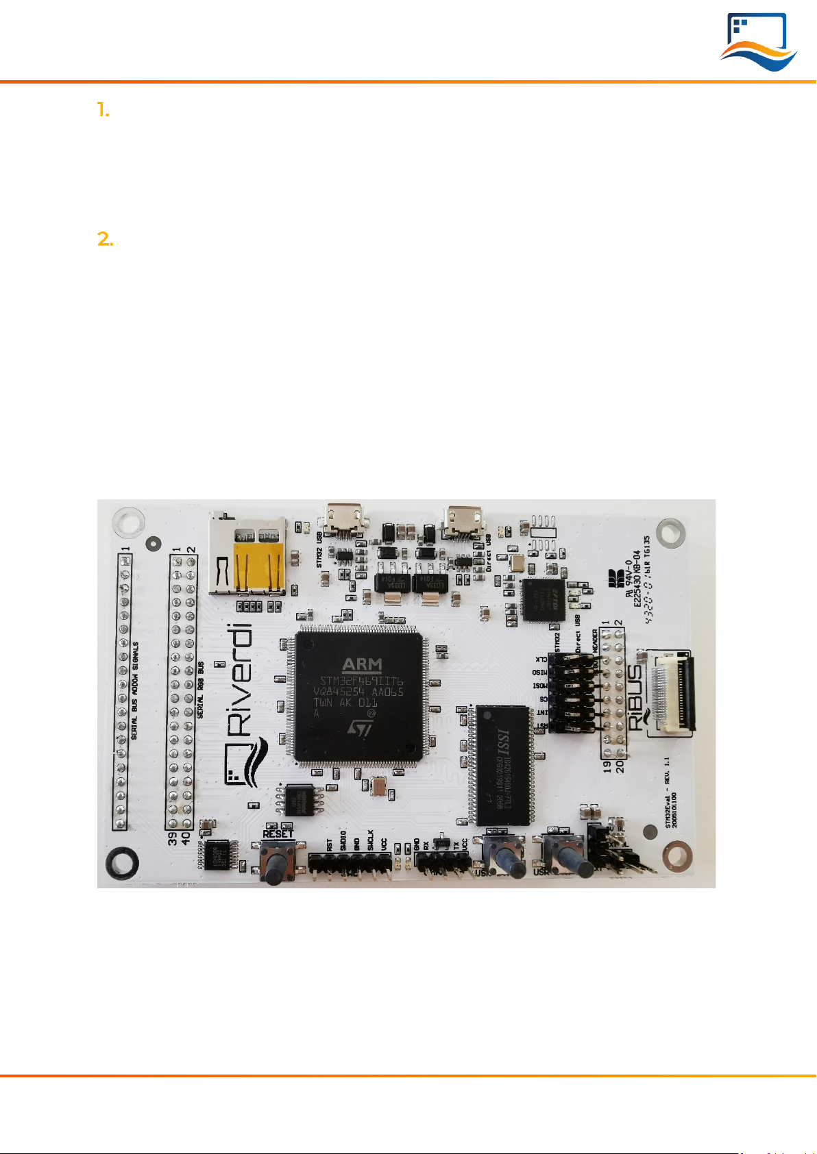
It features an STM32F469II Cortex-M4 microcontroller with: LCD parallel interface
including 8080/6800 modes, an LCD-TFT controller, Chrom-ART Accelerator™ for
enhanced graphic content creation (DMA2D), secure digital input/output interface
(SDIO), LTDC signals available on header P11 with additional MCU pins broken out
on P12, external SDRAM, MicroSD slot for data/media storage, RiBUS FFC conn P3
featuring SPI, UART and LCD supply pins (SPI can be controlled by either STM32 or
UBS serial bridge via jumper on P7/8/9) and configurable display backlight supply
(EXT/INT).

© 2022 Riverdi Page 6 of 19 www.riverdi.com
Riverdi STM32 Evaluation Board
INTRODUCTION
Riverdi STM32 Evaluation Board is a tool designed to help get you started on
working with Riverdi products. It’s not only EVE4 modules for displays from 3.5”
through 10.1” but also High Brightness, IPS displays with RGB, LVDS, DSI interfaces
(the two last types must have additional serializer) in combination with touch
panels by Riverdi.
You have three primary options to drive external displays:
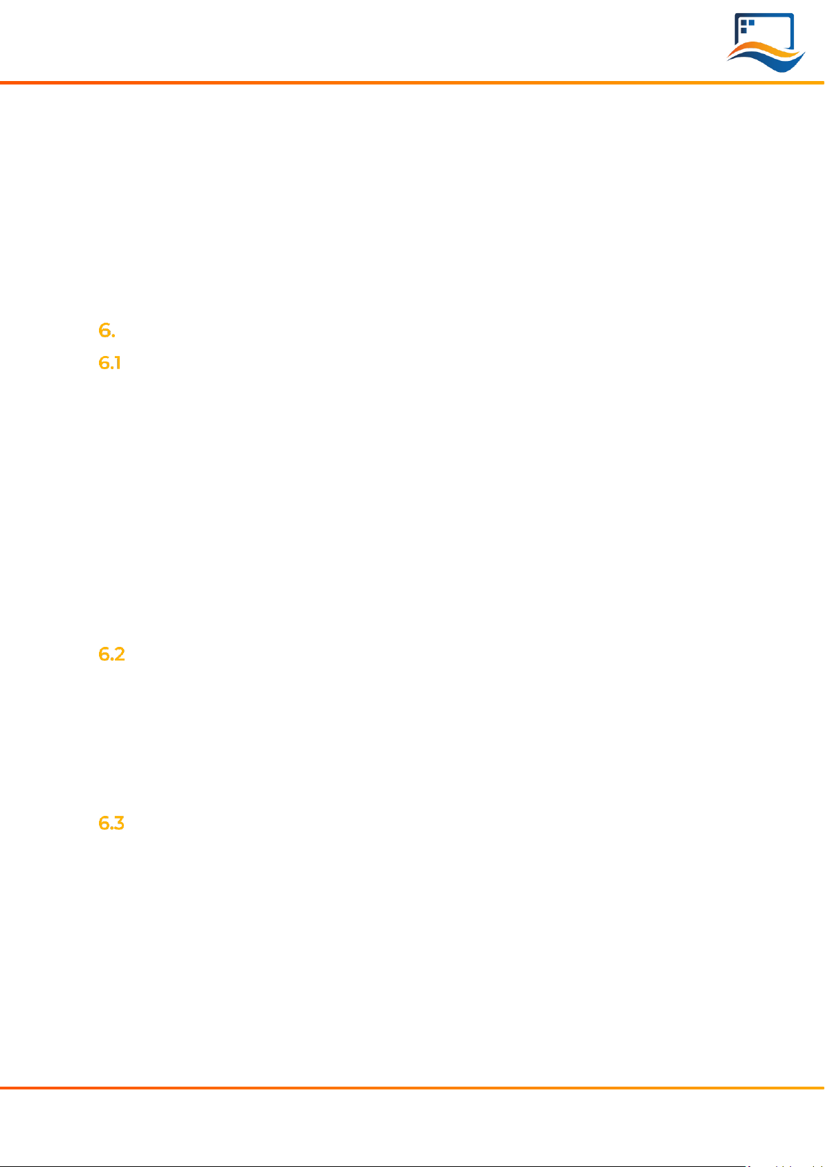
1. Jumper between P7 & P8: FTDI serial/SPI bridge connected to RiBUS SPI:
Use the FT232 serial to SPI bridge by connecting a micro-USB cable to the
connector labeled “Direct USB” and using the EVE Screen Editor to quickly
generate graphical user interfaces with minimum effort.
2. Jumper between P9 & P8: STM32 connected to RiBUS SPI:
Use the onboard STM32F4 to develop and test firmware for driving a connected
display or display controller, like Riverdi EVE4 intelligent display.
3. Extension Addon Board
Use extension Addon board to drive Riverdi High Brightness, IPS display without
EVE4 controller IC. An add-on board is the hardware interfacing device that
provides the necessary connection between LCD itself and STM32 Evaluation
Board. To make it possible to use many modules differing in size, signal
connectors and mechanical builds, addon boards are customized to the displays
they are serving.
BOARD FUNTIONALITY TEST
There are firmware examples with which you can test your Riverdi STM32
Evaluation Board. You can also use those as a starting point for your own firmware
development.

© 2022 Riverdi Page 7 of 19 www.riverdi.com
Riverdi STM32 Evaluation Board
INTERFACING WITH EVE DISPLAYS
This chapter describes the procedures of using the application EVE Screen Editor
(ESE) to create your own GUI application.
For quick start, Riverdi has prepared official, ready-to-use demonstration software
which is preloaded in the STM32 Flash memory for easy demonstration of the
Riverdi EVE4 series displays. Please refer to Chapter 6 for more details.
Using the FTDI SPI Bridge & EVE Editor
Prerequisites:
•Riverdi STM32 Evaluation Board
•EVE-enabled display
•RiBUS flexible flat cable (FFC)
EVE Screen Editor Installation
Download and install the EVE Screen Editor from below link:
https://brtchip.com/ic-module/toolchains/
Setup & Configuration
To connect the FTDI SPI bridge to the EVE4 display, the configuration jumpers
need to be placed between P7 and P8, as in the picture below.
Set the backlight jumper (placed over the backlight power configuration pins) to
5V BL on P4 (also refer to the picture below). Please see description on how to
connect power for backlight in section “Hardware features”, subsection “Backlight
power supply”.
© 2022 Riverdi Page 8 of 19 www.riverdi.com
Riverdi STM32 Evaluation Board
Start EVE Screen Editor and you will be greeted with the screen like the one
below:
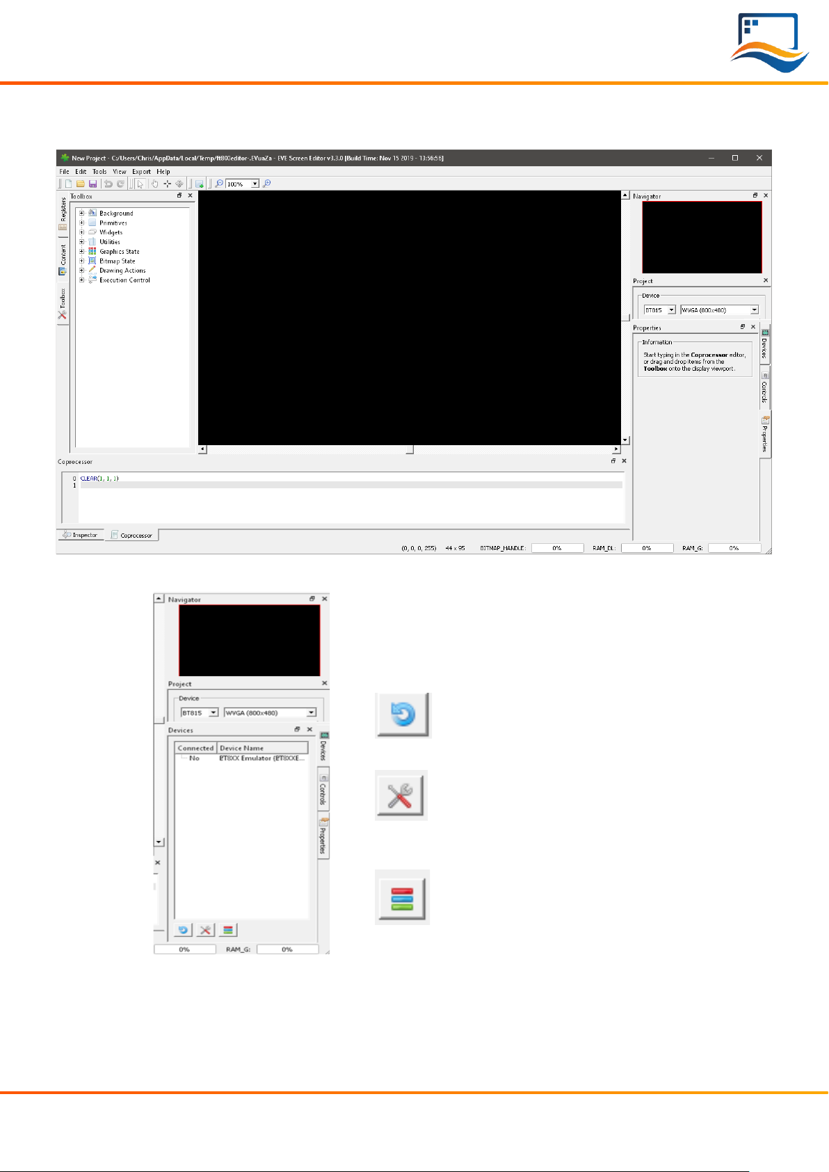
On the lower right-hand side of the window, click on the “Devices” tab.
On the lower left-hand side, you will
find 3 buttons:
This button refreshes the
devices list above it;
This button opens a menu to
select one from the
preconfigured displays list;
This button opens a menu to
define your own display to be
driven.
Use a USB cable to connect the “USB Direct” port to your computer, when
running the EVE Screen Editor application. Click the “Refresh” button afterwards
and your dev board should show up like in the picture below:
© 2022 Riverdi Page 9 of 19 www.riverdi.com
Riverdi STM32 Evaluation Board
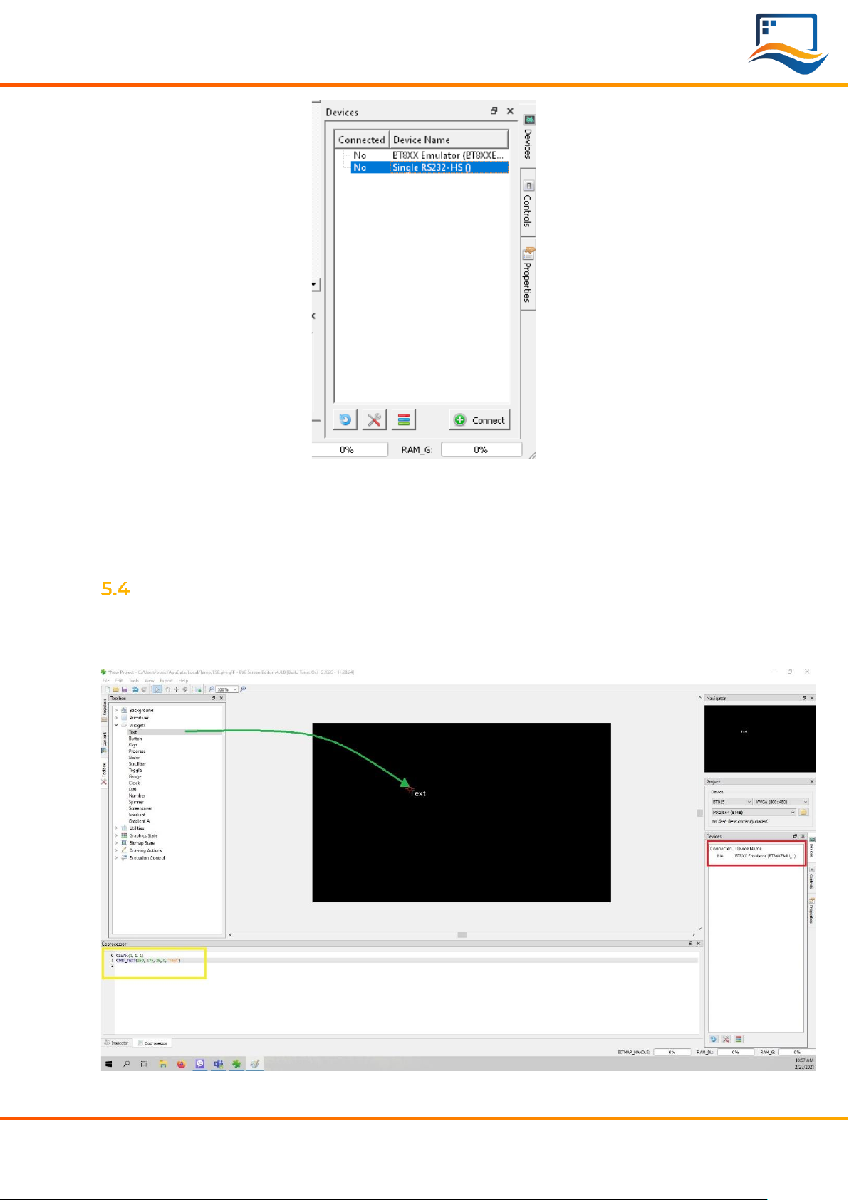
Select “Single RS232-HS ()” entry by clicking on it and use the ‘Connect’ button to
let EVE Screen Editor try and boot up your display.
If everything works properly, your display should show a blue screen with some
text.
Hello World
After connecting to STM32 Evacuation Board, to generate its first text message (e.
g. 'Hello World'), we are going to use the EVE Screen Editor’s built-in drag & drop
editor.
© 2022 Riverdi Page 10 of 19 www.riverdi.com
Riverdi STM32 Evaluation Board
(The drag operation is shown in green; the generated coprocessor commands
are shown in the yellow box and the button to send the data to the EVE display is
seen inside the red box.)
What you see now is the preview of what will be drawn on the physical screen in a
moment. Note that in the lower part of the window the coprocessor tab shows
which EVE pre-processor commands were generated and will be sent to the EVE4
display shortly after.
To send the commands also drawn in the preview pan to the physical display,
press the button labeled “Upload RAM_G and RAM_DL”.
EVALUATING RIVERDI EVE4 INTELLIGENT DISPLAY
A list of required items
•Riverdi STM32 Evaluation Board
•EVE4 enabled display
•RiBUS flexible flat cable (20 pins, 0.5mm pitch), 1 pcs
•Micro USB cable, 1 pcs
•Pre-loaded Micro SD card with demonstration files, 1 pcs
•2.54mm pitch, 2x6pins Jumper, 1 pcs
•2.54mm pitch, 1x2 pins Jumper, 1 pcs
Note 1: All accessories required are included into the package STM32 Evaluation
Board.
Note 2: When the board is extracted from its ESD bag, check that no component
remains in the bag. The main component to verify is the microSD card that may
have been ejected from the Micro SD Slot.
Software ready to use
Riverdi has prepared official, ready-to-use software for the STM32 Evaluation board.
The demonstration software is preloaded in the STM32 flash memory. And Mico SD
card is pre-loaded with images, hex file and flash bin file which are associated for
easy demonstration.
The latest versions of the demonstration source code and associated files can be
downloaded from Riverdi GitHub.
Configuration
First, please connect Riverdi EVE4 display to RiBUS connector (P3) STM32
Evaluation Board by using the 150 mm long FFC.
Second, the configuration jumpers, 2x6pins, need to be placed between P9 and
P8. Check the jumper and the USB cable position (in ‘STM32 USB’ socket) in the
picture below.
© 2022 Riverdi Page 11 of 19 www.riverdi.com
Riverdi STM32 Evaluation Board
Module power supply
Possible to deliver from one of two USB ports on STM32 Evaluation Board (“Direct
USB” or “STM32 USB”), in accordance with USB standard (5.0 VDC max.)
Backlight power supply
6.5.1 Internal
For display sizes from 3.5” to 5.0”, the USB port gives enough power to get
adequate backlight level. Such backlight power supply configuration (jumper is in
higher position, connects BL to 5V on P4) is shown in the picture below.
For 7.0” displays, USB minimal power capability needs to be 700mA @ 5V (this is a
combined power of STM32 Evaluation Board, BT817Q board and backlight). Please
make sure your USB source has enough current efficiency. If not, use external 5V
power source in the way described in chapter 6.5.2.

© 2022 Riverdi Page 12 of 19 www.riverdi.com
Riverdi STM32 Evaluation Board
6.5.2 External
All the 10.1” (and rarely certain 7.0” displays) require external power supply for
backlight, as the backlight voltage exceeds 5V and power consumption is over the
USB standard. To provide adequate backlight power, set the jumper in P4 to
lower position (it connects BL to EXT) –it must be placed in lower position and
connect the external DC voltage source to neighboring connector (“BL PWR”).
Refer to the picture and below.
Warning! There is no reverse polarity protection on EXT_BL_PWR, incorrect
connection will damage the backlight permanently. Proceed carefully.
EVE4 BT817Q TFT series backlight power requirement summary:
Display size
Internal (from USB)
External
3.5”
OK
3.3V-6.0V (optional)
4.3”
OK
3.3V-6.0V (optional)
5.0”
OK
3.3V-6.0V (optional)
7.0”
Ok, if USB has 700 mA min. efficiency
3.3V-6.0V (optional)
10.1”
External Power Only
5.0-14.0V (necessary)
For any additional information please refer to the datasheets of the specific
displays uploaded on our website:
https://riverdi.com/product-category/intelligent-displays/bt817q/

© 2022 Riverdi Page 13 of 19 www.riverdi.com
Riverdi STM32 Evaluation Board
Quick start
It’s very simple to get started using the demonstration software to evaluate
different Riverdi EVE4 display.
Just follow these 5 steps:
1. Configure the config.txt to set the display size and display type
Insert the SD card into the computer, you’ll need to find out the file named
“config.txt”. Double click to open the config.txt and set the parameters of
“display”(display size) and “eve” (display type)
Here is an example on setting the parameters of “display”and “eve” for Riverdi
7.0 inch with EVE4 intelligent controller on the board:
display=70
eve=1
Please always save the changes then insert the SD card back on the STM32
Evaluation Board.
2. Power on the module
For the configuration on power supply, please refer to subchapter 6.4 and 6.5.
3. Wait around 20s until both LED1 and LED2 switch on sequentially and
switch off completely.
Illuminated LED 1 indicates that the SMT32 flash is being erased.
Illuminated LED 2 indicates that the SMT32 flash is being programmed.
4. Press button “USR BTN1” to browse next picture and press button “RESET”
to restart the demonstration program.
5. Test the touch panel performance by painting on “Drawing test” page.
The “Drawing test” only applied for display with touch panel.
Change demonstration pictures
Warning! To change the demonstration picture successfully, the resolution and
format of the picture must be set correctly.
The resolution of the picture must be the same as the display itself resolution.
Pictures with BMP format can provide best demonstration effect. However, the
picture format must be RAW for Riverdi EVE4 7.0” and 10.1 “series.
Please refer to subchapter 6.8 on how to convert the picture format from BMP
into RAW.
1. Copy the new demonstration pictures to Micro SD card
Please copy new demonstration pictures to the folder named with the same
resolution as the picture.
2. Rename the new demonstration pictures with numbers
© 2022 Riverdi Page 14 of 19 www.riverdi.com
Riverdi STM32 Evaluation Board
First, delete or rename the pre-loaded demonstration pictures.
Second, rename the new demonstration pictures with any number from 0 to 3.
The number determines the sequence of demonstration pictures.
3. Loading new demonstration images
Insert the Micro SD card back and power up the module.
Additionally, to load new demonstration images for EVE4 displays 7.0” and 10.1”,
please keep holding button “BTN2”. Then press” RST” 1 time. Release the button
“BTN2” until loading images to flash memory will appear on the screen.
How to convert the picture format from BMP into RAW
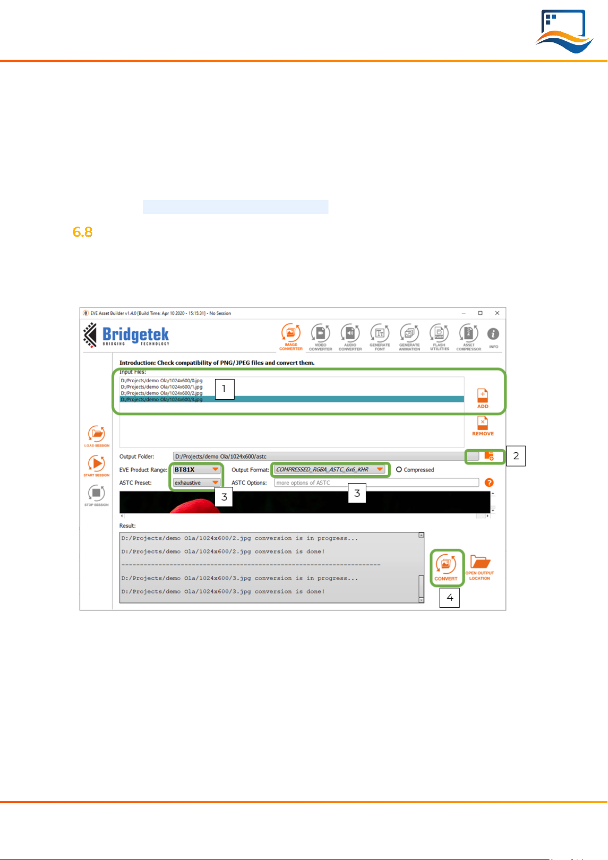
Steps on how to convert the picture format from .BMP into. RAW.
a) Download and install the latest version of EVE Asset Builder (EAB) from below
link: https://brtchip.com/ic-module/toolchains/
b) Run EVE Asset Builder and follow below 4 steps:
1. Add target picture with correct resolution
2. Locate the output folder path
3. Set the below 3 parameters as the above figure shows:
EVE Product Range:
BT81X
ASTC Preset:
exhaustive
Output Format:
COMPRESSED_RGBA_ASTC_6X6KHR
4. Click Convert
4 different types of files will be generated. However, please only keep the RAW file
and delete other 3 files.

© 2022 Riverdi Page 15 of 19 www.riverdi.com
Riverdi STM32 Evaluation Board
EVALUATING RIVERDI HIGH BRIGHTNESS, IPS DISPLAY
A list of required items
•Riverdi STM32 Evaluation Board
•Riverdi High Brightness, IPS display + Matching Don ADDON Board
•Micro USB cable, 1 pcs
•Pre-loaded Micro SD card with demonstration files, 1 pcs
•2.54mm pitch, 1x2 pins Jumper, 1 pcs
Note 1: All accessories required are included into the package of STM32 Evaluation
Board.
Note 2: When the board is extracted from its ESD bag, check that no component
remains in the bag. The main component to verify is the microSD card that may
have been ejected from the Micro SD Slot.
Software ready to use
The demonstration software is preloaded in the STM32 flash memory. And Micro
SD card is pre-loaded with images, hex file and flash bin file which are associated
for easy demonstration.
The latest versions of the demonstration source code and associated files can be
downloaded from Riverdi GitHub
Hardware configuration
First, Connect Riverdi High Brightness, IPS display to the matching Don Addon
Board.
Second, Plug on the STM32 Evaluation board on the top of the Don Addon Board.

© 2022 Riverdi Page 16 of 19 www.riverdi.com
Riverdi STM32 Evaluation Board
Module power supply
For the configuration on power supply, please refer to subchapter 6.4 and 6.5.
Quick start
It is very simple to get started using the STM32 Evaluation Board to evaluate the
Riverdi High Brightness, IPS displays.
Just follow these 5 steps:
1. Configure the config.txt to set the display size and display type
Insert the SD card into the computer, you’ ll need to find out the file named
“config.txt”.
Double click to open the config.txt and set the parameters of “display” (display
size) and “eve” (display type)
Here is an example on setting the parameters of “display” and “eve”for Riverdi
High Brightness, IPS 7.0 inch without EVE4 intelligent controller on the board:
display=70
eve=0
Please always save the changes then insert the SD card back on the STM32
Evaluation board.
Warning! To evaluate Riverdi High Brightness, IPS 10.1" series display with LVDS
interface, eve=1 is the only option. Because EVE4 controller is already on Don
Addon 101.
2. Power on the module
For the configuration on power supply, please refer to subchapter 6.4 and 6.5.
3. Wait around 20s until both LED1 and LED2 switch on sequentially and switch
off completely.
Illuminated LED 1 indicates that the SMT32 flash is being erased.
Illuminated LED 2 indicates that the SMT32 flash is being programmed.
4. Press button “USR BTN1” to browse next picture and press button “RESET”
to restart the demonstration program.
5. Test the touch panel performance by painting on “Drawing test” page.
The “Drawing test” only applied for display with touch panel.
Change demonstration pictures
Warning! To change the demonstration picture successfully, the resolution and
format of the picture must be set correctly.
The resolution of the picture must be the same as the display itself resolution and
pictures with BMP format can provide best demonstration effect.
Warning! Because EVE4 controller is already on Don Addon 101, the picture
format must be RAW when changing the demonstration pictures for Riverdi High
Brightness, IPS 10.1 “series.

© 2022 Riverdi Page 17 of 19 www.riverdi.com
Riverdi STM32 Evaluation Board
Please refer to sub chapter 6.8 on how to convert the picture format from BMP
into RAW.
1. Copy the new demonstration pictures to Micro SD card
Please copy new demonstration pictures to the folder
2. Rename the new demonstration pictures with numbers
First, delete or rename the pre-loaded demonstration pictures.
Second, rename the new demonstration pictures with any number from 0 to 3.
The number determines the sequence of demonstration pictures.
3. Load the new demonstration images
Insert the Micro SD card back and power up the module.
Warning! To load new demonstration images for Riverdi High Brightness, IPS 10.1”
series, please keep holding button “BTN2”. Then press” RST” 1 time. Release the
button “BTN2” until loading images to flash memory will appear on the screen.
HARDWARE LAYOUT
Microcontroller
STM32F469II, Arm Cortex-M4 MCU @ up to 180 MHz
External SDRAM
IS42S16400J, 64 Mbit
http://www.issi.com/WW/pdf/42-45S16400J.pdf
FTDI serial to SPI Bridge
https://www.ftdichip.com/Support/Documents/DataSheets/ICs/DS_FT232H.pdf
Micro SD slot
When functional microSD card is placed in this slot, after being formatted in
FAT32 format, microSD card’s memory space can be used by microcontroller as
the regular filesystem.
RiBUS connector
Support for BT817Q (max SPI speed = 30MHz),
https://riverdi.com/product/zif0520dh-cf25/
FTDI app note AN312 contains c headers and example code for FT800.
User LEDs: 2 pcs
They can be configured by the user, from program level.
Power LED indicating power to FTDI “DIRECT USB”
FTDI input powers both rails.
Power LED indicating power to “STM32 USB”
STM32 powers its own rail only.

© 2022 Riverdi Page 18 of 19 www.riverdi.com
Riverdi STM32 Evaluation Board
User buttons: 2 pcs
These may be used in future; they are not used.
Serial RGB bus header
Please refer to Application Note: ST AN4861 (LCD-TFT display controller (LTDC) on
STM32 MCUs).
ADDITIONAL LITERATURE
All the below sources contain the data of BT817 (EVE4) ICs.
BT81x, General and Datasheets:
https://brtchip.com/ic-module/product-category/products/ic/eve4-ic/
BT81x, Programming Guides:
https://brtchip.com/ic-module/document/programming-guides/
SUMMARY
If this document has made you interested in knowing more about Riverdi products,
please visit Riverdi website:
https://riverdi.com/product-category/evaluation-boards/

© 2022 Riverdi Page 19 of 19 www.riverdi.com
Riverdi STM32 Evaluation Board
WARRANTY LIMITATION
End user is instructed how to connect external power sources to the unit, which
brings the potential threats to the STM32 Evaluation Board and display. Riverdi
cannot be held responsible for actions beyond its control and consequently the
warranty DOES NOT cover the effects of reversed power supply polarity on
backlight terminals. Refer to clause in red color in section 6.5.2 EXTERNAL of this
document.
LEGAL INFORMATION
This document has been issued for informational purposes only. Riverdi did their
best to avoid any errors, but we do not grant full warrant it is 100% errors free. Please
contact Riverdi if you find any mistakes or when you think some important
information is missing in this Manual. It can be updated or altered without any
written notice. Riverdi cannot be held responsible for not announcing any changes
or issuing next revisions or versions of this document.
Other manuals for STM32
1
Table of contents
Other Riverdi Motherboard manuals


