Rives Audio PARC User manual

© Copyright 2002 Rives Audio, Inc. Page 1
PARC
Operator’s Manual
Thank you for purchasing the PARC, Parametric Adaptive Room Compensation, System. As you are already
well aware, high end audio systems and even mid-fi systems have reached a level that exceeds the
performance of the room they are in. All of Rives Audio products and services are designed to compensate
these room anomalies and provide the listener with a more rewarding listening experience.
The PARC was developed by engineers with years of experience in high end professional mixing boards. It is
these parametric compensation systems that are employed in the PARC. All of the components are the finest
available. All of the signal paths are as short as possible. All power supplies are quiet, reliable, and built
beyond the needs of the system. All display and control electronics are isolated as much as possible from the
signal path. The result is a system that can enhance even the finest high end system.
The PARC also uses a software control system. This allows for easy upgrading of the software. Over time we
may find ways of enhancing the product and this architecture will allow the user to upgrade the software very
easily.
Topics: Page
Connections 2
Basic Function 4
Set-up 5
Memory 8
Troubleshooting 9
Appendix A SPL meter correction 10
Appendix B Q factor and Frequency Comparison 11
Appendix C Chart for Plotting Loudspeaker and Room Response 12
Specifications 13
Contact Information 13

Page 2 © Copyright 2002 Rives Audio, Inc.
PARC
Operator’s Manual
The connections for the PARC are very simple. We provide both balanced and single ended inputs and
outputs. The actual topology of the PARC is a fully balanced design. If you have the capability of using
balanced connections, we recommend this method. You can also use the PARC to convert from balanced to
single ended and vise versa. However, the power off bypass only works if you are either going from balanced
in to balanced out or single ended in to single ended out. The front panel bypass will work if you are using the
PARC to convert from single ended to balanced or vise versa, it bypasses the filter circuitry.
The PARC can either be connected via a tape loop, or between pre-amp outs and amplifier in. In cases where
a separate amplifier and pre-amp are used it is preferable to connect the PARC between the two.
When connecting the PARC via a pre-amp and amp, connect the line in on the PARC to the outputs on the
pre-amp. Then connect the line out on the PARC to the inputs on the amplifier. Below is an example of the
PARC connected via the XLR (balanced connectors). Keep in mind that single ended inputs could be used, or
a combination. Which ever connection is used on the input the correct switch position (RCA vs XLR) must be
selected.

© Copyright 2002 Rives Audio, Inc. Page 3
PARC
Operator’s Manual
When connecting the PARC via a tape loop, connect the line in on the PARC to the tape record outs on the
receiver or pre-amp. Then connect the line out on the PARC to the tape in on the receiver or pre-amp. The
example shown below is with single ended inputs, which is the most likely to be used with a tape loop. When
using single ended inputs the input switch must be switched to “RCA” on the back panel. It is possible to use
the XLR (balanced connections) or a combination of the two. If a combination of the two is used, in particular
single ended into the PARC and balanced out, care should be taken to insure that the tape loop is not
overloaded by the added gain.
There are two communications ports on the rear panel. One uses 6 pin XLR connector and is labeled “link”.
It is designed to be used with the PARC plus. The PARC plus adds an additional 4 channels of parametric
equalization. The PARC handles all the controls for the PARC plus. The other communication port is a
standard RS-232 port and is labeled “comm port”. This allows a computer to communicate directly with the
PARC. There are two uses for this, one is for software upgrades, the other is for communications with the
BARE software package. For more information on this software package visit Rives Audio at
www.rivesaudio.com.
There is also a detachable IEC power cord. This allows the user to upgrade the power cord.
You will also notice the power switch is on the back of the unit. The unit should be left on at all times.

Page 4 © Copyright 2002 Rives Audio, Inc.
PARC
Operator’s Manual
Basic Function
The basic function of the PARC is to minimize bass anomalies in the room. The most prominent bass
anomalies occur when two parallel walls (or floor and ceiling) excite a particular frequency. The distance
between the two walls determines which frequency is excited. The most problematic, or highest amplitude, is
generally ½ of a wavelength between two walls. The way to calculate the distance is:
½ * speed of sound / distance between walls = Frequency
The speed of sound is 1130 feet per second. Thus a room with 17 foot spaced walls would have a frequency
bump at:
565 / 17 = 33.2 Hz.
This is considered the first mode between those two walls. The second mode is for a full wavelength, which
would be at 66.4 Hz. The third mode would be at 3/2 wavelengths, or 99.6 Hz. Each mode has lower
amplitude than the previous mode. However, imagine a room where the length is 2 times the width. In this
example 34 feet long. The first mode for that room is at the same frequency of the second mode of the width,
or 66.4 Hz. When modes combine like this the problem is compounded, and the bass can become very
bloated and distorted.
Even at Rives Audio we recommend reducing any bass anomalies as much as possible before employing the
PARC; the less electrical equalization the better. However, over damping a room, or filling it with bass traps
can be impractical, expensive, and may not lead to the best sounding environment. The PARC employs the
highest grade components and shortest signal paths possible. The goal is to make these alterations to
compensate for bass problems with as little effect as possible on anything else in the audio chain.
The PARC operates between 16 and 350 Hz. It attenuates ONLY, there is no gain in the PARC. The purpose
is to reduce the frequencies caused by room excitation. There are three bands per channel. These three
bands were originally designed to compensate for the 3 parallel surfaces in most rectangular rooms (side to
side, front to back, and floor to ceiling). However, they can be cascaded or used in a variety of settings to best
suit the room.
For each band there are 3 settings: frequency, width, and attenuation. Frequency is the center frequency that
will be attenuated. It is represented in Hz. Attenuation is the dB in attenuation. The number is positive, but
the function is reducing the amplitude at that frequency by the dB shown on the display. The range is from 0
to 18 dB. If it is set to zero, then no attenuation is employed. Width is expressed by a Q factor, or “quality”
factor. The Q factor is expressed as:
Center Frequency (Hz) / the Width (Hz) at 3dB below the peak frequency.
Thus the higher the Q the narrower the band of attenuation.
As an example a Center Frequency at 100 Hz, with a width of 25 Hz, would have a Q of 4. Also, Q can be
expressed in terms of Octaves. One Octave doubles the frequency. Keep in mind that Frequency is a log
function of Octaves, so a center frequency of 100 Hz with a width of one octave is not exactly 100Hz, it’s more
than 100Hz. In our example of 100 Hz center frequency and a width of 25Hz, the relative octave width is
approximately ¼. The Q factor is inversely proportional to the octave width. This is not important, unless you
are a musician and more comfortable with octaves. All instructions for set-up will be relative to Hertz, and the
Q factor.
The width will change depending on what types of walls, floor, or ceiling you have. In general hard, rigid
surfaces, such as concrete, will exhibit a high Q factor, whereas sheetrock on wood studs will exhibit a low Q
factor. The lowest Q factor the PARC can produce is 1. This is much broader than we ever anticipate using.
The narrowest Q factor is 10. For more information on Q factors see appendix B.
© Copyright 2002 Rives Audio, Inc. Page 5
PARC
Operator’s Manual
Set-up
There are two methods for set-up. The easiest method is to use the BARE software and microphone. The
BARE performs all the calculations and stores the optimum settings in the PARC in a semi-automated method.
To use this method please refer to the BARE operators manual.
The second method is a manual method and requires more time and diligence on the users part. With this
method the user will need an SPL meter and the charts that are provided in the back of this manual. We
recommend making copies of the chart, as it is likely you will use this multiple times. If the SPL meter is C
weighted, see the appendix in this manual for the corrections of a C weighted meter. You will need to add
these numbers to your measurements to get accurate readings. We recommend the Radioshack analog C
weighted meter. You will also need a source of test tones from 20 to 500 Hz. You can go to higher
frequencies, but the PARC will only compensate for frequencies below 512 Hz.
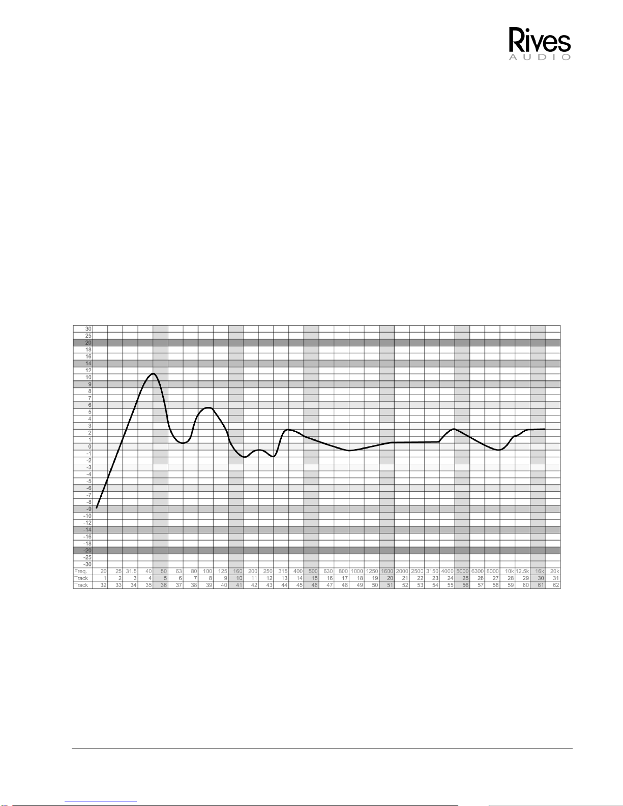
The first step in setting up the PARC is measuring the room and loudspeaker response. Placement of the
meter is important. It should be placed at the typical listener position. If you have a tripod, this is the best way
to insure a stable an accurate placement of the meter. If you do not, place the meter where the listener’s head
would be. Try to avoid supporting it by any object that would block sound. Go through the frequency
spectrum for each loudspeaker independently (as the PARC allows you to set the speakers independently),
and measure the response. Below is a chart of a single loudspeaker in a room.
There is an average width peak around 40 Hz and another broader peak around 100 Hz. The very modest
peak at 315 Hz is only 2 dB and is not likely to be audible. In this case we will only use 2 of the three bands
available.

Page 6 © Copyright 2002 Rives Audio, Inc.
PARC
Operator’s Manual
Next we will determine the peaks and widths of these two frequencies. The peak at 40 Hz is approximate 10
Hz wide at 3 db below the maximum peak. This would yield a Q factor of 40 / 10 = 4.
Next we would determine the second peak. The center frequency is 100 Hz. The peak is 5 dB, and the width
at –3dB point is approximately 50 Hz. This would yield a Q of 2. If a peak is less than 3 dB above the
reference level, say 1.5 dB it would not be necessary to use a filter on that frequency. Q factors are always
calculated at the -3db point from the peak. If you want to calculate the Q just extrapolate the line to 3 dB
below the peak and calculate the width there.
These settings should be written down, so that they can then be saved to the PARC.
Left Channel, Band 1: Frequency = 40 Hz, Width = 4, Attenuation = 10 dB
Left Channel, Band 2: Frequency =100 Hz, Width = 2, Attenuation = 5 dB
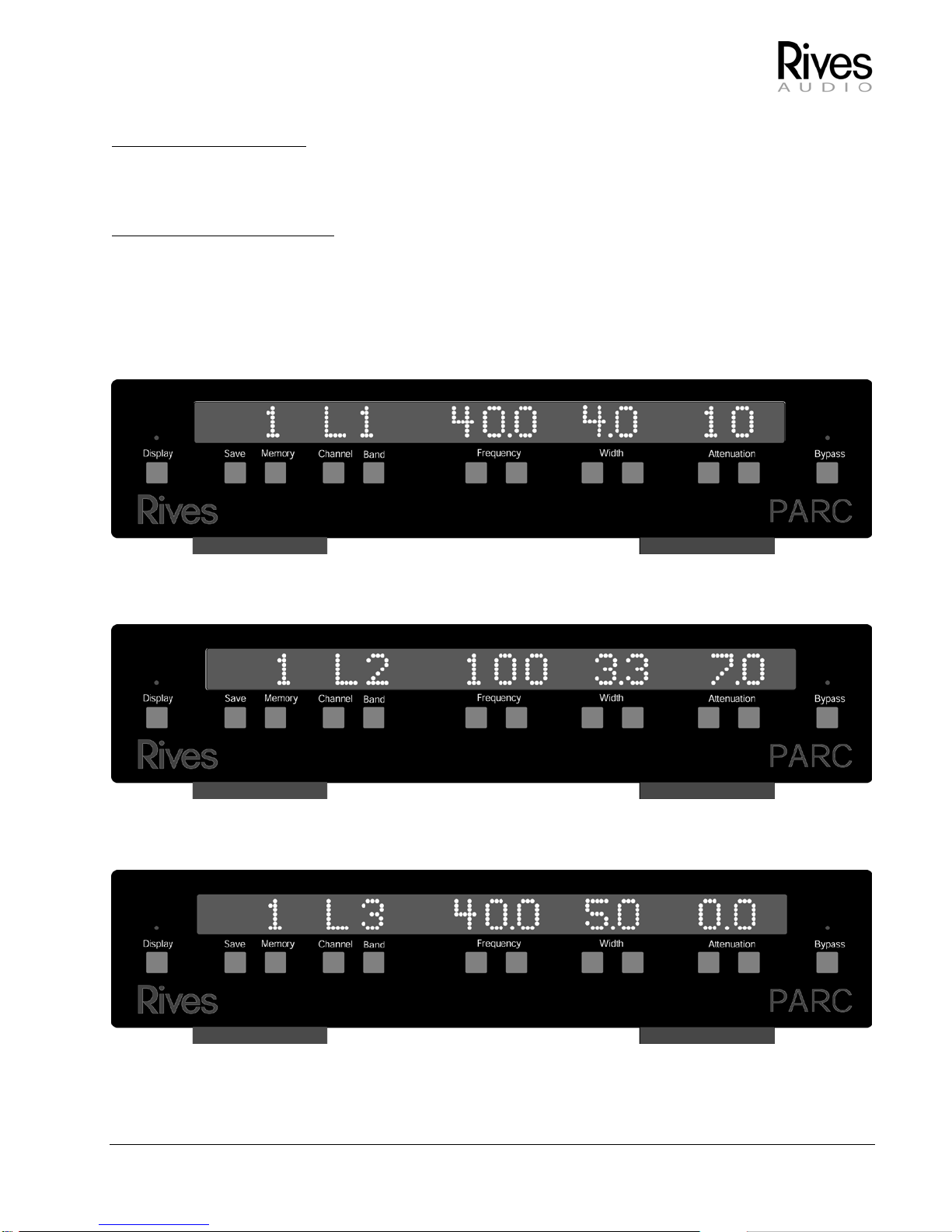
The following diagram shows the basic button functions.
© Copyright 2002 Rives Audio, Inc. Page 7
PARC
Operator’s Manual
First the display must be on. If the red light is lit above the display, and there are no lights in the main panel,
press the display button. The red light should turn off, and there should be a complete set of readings in the
panel. We recommend that you leave the display off unless you are setting up the PARC. When the display is
off, all keys, except the bypass, are not functional. You can only change the settings with the display on.
Second the bypass must be out. If the red light is lit over bypass, the bypass is in. Settings can not be
changed when the bypass is in.
It doesn’t matter the memory setting when you begin. The first thing to do is select the channel to “L” by
pressing the channel select button. Then select the band to 1, by pressing the band select until “1” reads
above the band. Next select the frequency by pressing either frequency up or frequency down until 40 reads
above the frequency. Select the width to 2 in a similar manner and select the attenuation to 10.0. The panel
should look like the following:
Next set up the second band. Select the band to “2” first. Then make the appropriate settings. Do NOT
change the memory setting at this time. The panel should look like the following:
Lastly set the third band. Even though we are not using it, you must insure that it is set to “0.0” attenuation.
The frequency and width do not matter. It should look something like:
Now the left channel is set. To set the right channel. Repeat the measurements, and set it in a similar
fashion. Remember, do not change the memory select during this process.
Page 8 © Copyright 2002 Rives Audio, Inc.
PARC
Operator’s Manual
Save
Now that both channels have been set up, it’s time to save this to memory. There are 3 memories. While the
PARC is primarily designed to be left in one particular compensation mode, the memory settings allow the
user flexibility to tailor the sound for particular situations. We recommend that the flattest response be set to
memory 1 and then tailored responses set to memory 2 and 3. Initially there are no memory presets. The unit
will therefore initially come up with no memory. Any time the unit is powered down, the unit will then power up
with those settings. Thus if it were a memory setting, it will then display the memory it was in. If it was not a
memory setting, it will still come up with that setting but will not display a memory.
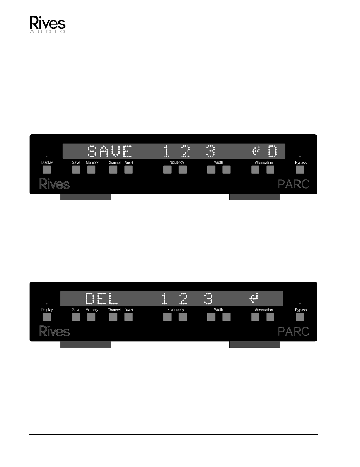
To save a particular setting to memory, program in that setting as described in the previous section. Then
press the save button and hold it down for 1 second. The following screen will appear:
To save a particular memory the user should press the button corresponding the memory location they which
to save to. This will enter the data into memory. If any numbers are double in width, this means something is
already stored in this location. By pressing that button, anything previously stored in that location will be
erased, and re-written with the new data. If they do not wish to save to memory and return to the main mode,
they should press the left attenuation button to return. This will cancel the save operation.
While in save mode, the user can access the delete memory mode. It is possible that the user has set 3
memories, but finds they only toggle through 2 of them and would like to delete one of the other memory
location. While the save screen is showing, the user should press the right attenuation button. The following
screen will appear:
Similar to the memory mode, the user can then delete memory 1, 2 or 3. If the user has entered this mode in
error, they can simply press the left Attenuation key and exit back to the main mode of operation.
Once data is stored into the memory locations the memory button toggles through these saved settings. If
there is only one memory saved, this is the only one that is accessible. If others are saved it will simply scroll
through those.

© Copyright 2002 Rives Audio, Inc. Page 9
PARC
Operator’s Manual
Troubleshooting
No sound through the system:
Be sure the appropriate switch on the back panel is selected. If you are using RCA inputs, the RCA switch
position must be selected, if you are using XLR inputs, the XLR must be selected. This selection is for input
only, it does not matter what the output connection is.
Are any lights on, there should always be at least one light on or the display should be on. If there are no
lights, either there is no power to the unit, or the fuse has gone bad.
Check power, and / or replace fuse.
If you are using a tape loop, be sure the tape mute is not on the loop.
I can’t go above 350 Hz Frequency:
This is normal operation. The unit only functions between 16 and 350 Hz.
The BARE is not communicating with the PARC:
Please see the BARE manual for this. There is a communications troubleshooting protocol built into the
software. It can best be handled from the BARE.
Why can’t I go above 18dB attenuation:
You can by cascading 2 bands at the same center frequency. This is typically not recommended except for
extreme cases, or when there is a broad band overlapped by a narrow band.

Page 10 © Copyright 2002 Rives Audio, Inc.
PARC
Operator’s Manual
Appendix A
SPL meter correction
With a C weighted meter, such as the Radioshack SPL analog meter, the following dB should be added at the
corresponding frequency. This corrects for the non-linearity incorporated by C weighting.
Hz
Correction
10
20.5
12.5
16.5
16
11.5
20
7.5
25
5
31.5
3
40
2.5
50
1.5
63
1.5
80
1.5
100
2
125
0.5
160
-0.5
200
-0.5
250
0.5
315
-0.5
400
0
500
-0.5
630
0
800
0
1000
0
1250
0
1600
-0.5
2000
-1.5
2500
-1.5
3150
-1.5
4000
-2
5000
-2
6300
-2
8000
-2
10000
-1
12500
0.5
16000
0
20000
1
Compensation Numbers Copyrighted by Granite Audio, with all rights reserved, and used here with their kind permission.
These numbers also verified by our own extensive in-house testing.

© Copyright 2002 Rives Audio, Inc. Page 11
PARC
Operator’s Manual
Appendix B
Chart for Q Factor Comparison
Below is a chart that compares Q Factors to the Width in Hertz, at 3 different center frequencies. The
relationship of the Q factor to the octaves remains constant, while the width in Hertz changes with varying
center frequencies. The PARC is set up with constant Q factor circuitry. It is for this reason that the width is
expressed in terms of Q factors.
Width @ 200 Hz
Width @ 125 Hz
Width @ 40 Hz
Q Factor
200.0
125.0
40.0
1 200.0 125.0 40.0
1.5
133.3
83.3
26.7
1.6
125.0
78.1
25.0
1.7
117.6
73.5
23.5
1.8
111.1
69.4
22.2
2
100.0
62.5
20.0
2.2
90.9
56.8
18.2
2.5
80.0
50.0
16.0
2.9
69.0
43.1
13.8
3
66.7
41.7
13.3
3.5
57.1
35.7
11.4
4
50.0
31.3
10.0
4.5
44.4
27.8
8.9
5
40.0
25.0
8.0
5.5
36.4
22.7
7.3
6
33.3
20.8
6.7
7
28.6
17.9
5.7
8
25.0
15.6
5.0
9
22.2
13.9
4.4
10
20.0
12.5
4.0

Page 12 © Copyright 2002 Rives Audio, Inc.
PARC
Operator’s Manual
Appendix C: Frequency Chart for plotting loudspeaker and room response
This chart is best used with the Rives Audio Test CD and a Radio Shack SPL analog meter.
You may download additional copies of this chart at http://www.rivesaudio.com/files/freqchrt.PDF

© Copyright 2002 Rives Audio, Inc. Page 13
PARC
Operator’s Manual
Specifications:
Storage temperature: -40 to 250 degrees F
Operating temperature: 32 to 120 degrees F
Dimensions (inches): 17 W x 4 H x 12.5 D
Voltage: 100, 120, 220, 240 selectable
Power consumption: 50 W
Power cord: Detachable, standard IEC
Inputs: RCA and XLR, input impedance >10k ohms
Outputs: RCA and XLR, output impedance <100 ohms
Number of Channels: 2 channels (right and left)
Number of Bands per Channel: 3 bands per channel
User selectable parameters:
•Center Frequency: 16 Hz to 350 Hz, independent per band and channel
•Width Q: 1 to 10, independent per band and channel
•Attenuation Level: 0 to 18 dB, independent per band and channel
Contact Information:
Rives Audio
The ATI Group, Ste A-1
8301 Patuxent Range Road
Jessup, MD 20794
Phone 800-959-6553
www.rivesaudio.com
for Service and Warranty contact:
service@rivesaudio.com
Table of contents


