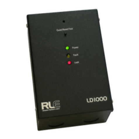
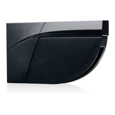
RLE Technologies SeaHawk LD2000 User manual

Leak Detection
LD2000 User Guide

rletech.com 2 970.484.6510
Copyright Notice
©2010 RLE Technologies. All rights reserved. No part of this publication may be reproduced or
distributed in any form or by any means, or stored in a database or retrieval system, without the
prior written permission of RLE Technologies.
Trademark Notices
RLE is a registered trademark and Falcon, Raptor, and SeaHawk are trademarks of RLE
Technologies. All other trademarks or registered trademarks are the property of their respective
companies.
Revision History
Part number 110051
Note: As necessary, blank pages are added to make the page count even.
Rev. No. Date
2.0 June 2010
2.1 October 2010

970.484.6510 3 rletech.com
Product Registration
Product registration helps RLE Technologies inform owners of:
• Product upgrades
• Firmware enhancements
• New products and technologies
• Special offers available only to registered users
Submit registration information on the Support/Product Registration webpage at www.rletech.com.
Any information provided to RLE Technologies through the registration form will be regarded as
confidential. RLE will not sell or distribute any of the information to third parties. To read our
Privacy Policy, please visit our website: www.rletech.com.
Technical Support
Personal assistance is available Monday through Friday, from 8:00 a.m. to 5:00 p.m. MST.
A request for assistance may be sent to support@rletech.com.
Otherwise, please call us directly at: (970) 484-6510, and press “2” for technical support.
The following information is located on the bottom of each LD2000 unit. Please have this
information available whenever a technical support call is placed:
Product Model Number
Product Serial Number
Product Manufacture Date

970.484.6510 4 rletech.com
Notes:

Contents
rletech.com 5 970.484.6510
1 Product Overview . . . . . . . . . . . . . . . . . . . . . . . . . . . . . . . . . . . . . . . . . . . . . . . . 11
Description . . . . . . . . . . . . . . . . . . . . . . . . . . . . . . . . . . . . . . . . . . . . . . . . . . . . . . . . . . . . . . . . . . . 11
Operation . . . . . . . . . . . . . . . . . . . . . . . . . . . . . . . . . . . . . . . . . . . . . . . . . . . . . . . . . . . . . . . . . . . . 11
Mechanical Description . . . . . . . . . . . . . . . . . . . . . . . . . . . . . . . . . . . . . . . . . . . . . . . . . . . . . . . . . . 12
Installation . . . . . . . . . . . . . . . . . . . . . . . . . . . . . . . . . . . . . . . . . . . . . . . . . . . . . . . . . . . . . . . . . . . . 12
Reference Map . . . . . . . . . . . . . . . . . . . . . . . . . . . . . . . . . . . . . . . . . . . . . . . . . . . . . . . . . . . . . . . . 12
Web Interface . . . . . . . . . . . . . . . . . . . . . . . . . . . . . . . . . . . . . . . . . . . . . . . . . . . . . . . . . . . . . . . . . 12
2 Connections and Settings . . . . . . . . . . . . . . . . . . . . . . . . . . . . . . . . . . . . . . . . . 15
Reset. . . . . . . . . . . . . . . . . . . . . . . . . . . . . . . . . . . . . . . . . . . . . . . . . . . . . . . . . . . . . . . . . . . . . . . . 16
Connections . . . . . . . . . . . . . . . . . . . . . . . . . . . . . . . . . . . . . . . . . . . . . . . . . . . . . . . . . . . . . . . . . . 16
TB1: Input Power . . . . . . . . . . . . . . . . . . . . . . . . . . . . . . . . . . . . . . . . . . . . . . . . . . . . . . . . . . 16
P1: Input Power . . . . . . . . . . . . . . . . . . . . . . . . . . . . . . . . . . . . . . . . . . . . . . . . . . . . . . . . . . . 16
TB2: Cable Interface . . . . . . . . . . . . . . . . . . . . . . . . . . . . . . . . . . . . . . . . . . . . . . . . . . . . . . . 16
TB3: Summary Relay . . . . . . . . . . . . . . . . . . . . . . . . . . . . . . . . . . . . . . . . . . . . . . . . . . . . . . . 17
P4: EIA-232 Connector . . . . . . . . . . . . . . . . . . . . . . . . . . . . . . . . . . . . . . . . . . . . . . . . . . . . . 17
SW3: EIA-485 Termination . . . . . . . . . . . . . . . . . . . . . . . . . . . . . . . . . . . . . . . . . . . . . . . . . . 17
TB4: EIA-485 Modbus Port . . . . . . . . . . . . . . . . . . . . . . . . . . . . . . . . . . . . . . . . . . . . . . . . . . 17
P3: RJ45 Network . . . . . . . . . . . . . . . . . . . . . . . . . . . . . . . . . . . . . . . . . . . . . . . . . . . . . . . . . 17
3 Installation . . . . . . . . . . . . . . . . . . . . . . . . . . . . . . . . . . . . . . . . . . . . . . . . . . . . . . 19
Installing the LD2000 . . . . . . . . . . . . . . . . . . . . . . . . . . . . . . . . . . . . . . . . . . . . . . . . . . . . . . . . . . . 19
Connecting the SeaHawk Leak Detection Cable . . . . . . . . . . . . . . . . . . . . . . . . . . . . . . . . . . . . . . 19
Securing Cable to the Floor . . . . . . . . . . . . . . . . . . . . . . . . . . . . . . . . . . . . . . . . . . . . . . . . . . 20
Applying Power to the LD2000. . . . . . . . . . . . . . . . . . . . . . . . . . . . . . . . . . . . . . . . . . . . . . . . 21
Communication . . . . . . . . . . . . . . . . . . . . . . . . . . . . . . . . . . . . . . . . . . . . . . . . . . . . . . . . . . . 22
Set the LD2000's IP Address. . . . . . . . . . . . . . . . . . . . . . . . . . . . . . . . . . . . . . . . . . . . . . 22
4 Web Interface . . . . . . . . . . . . . . . . . . . . . . . . . . . . . . . . . . . . . . . . . . . . . . . . . . . 25
Home. . . . . . . . . . . . . . . . . . . . . . . . . . . . . . . . . . . . . . . . . . . . . . . . . . . . . . . . . . . . . . . . . . . . . . . . 26
Historical Data. . . . . . . . . . . . . . . . . . . . . . . . . . . . . . . . . . . . . . . . . . . . . . . . . . . . . . . . . . . . . . . . . 27
Trend Log. . . . . . . . . . . . . . . . . . . . . . . . . . . . . . . . . . . . . . . . . . . . . . . . . . . . . . . . . . . . . . . . 28
Configuration. . . . . . . . . . . . . . . . . . . . . . . . . . . . . . . . . . . . . . . . . . . . . . . . . . . . . . . . . . . . . . . . . . 29
Leak Settings . . . . . . . . . . . . . . . . . . . . . . . . . . . . . . . . . . . . . . . . . . . . . . . . . . . . . . . . . . . . . 29
Zone Configuration. . . . . . . . . . . . . . . . . . . . . . . . . . . . . . . . . . . . . . . . . . . . . . . . . . . . . . . . . 31
Zone 1-8 Settings. . . . . . . . . . . . . . . . . . . . . . . . . . . . . . . . . . . . . . . . . . . . . . . . . . . . . . . . . . 32
Network Settings/ IP Configuration . . . . . . . . . . . . . . . . . . . . . . . . . . . . . . . . . . . . . . . . . . . . 32
Web Settings/ Configuration . . . . . . . . . . . . . . . . . . . . . . . . . . . . . . . . . . . . . . . . . . . . . . . . . 33
Email/DNS . . . . . . . . . . . . . . . . . . . . . . . . . . . . . . . . . . . . . . . . . . . . . . . . . . . . . . . . . . . . . . . 34
NTP (Network Time Protocol) . . . . . . . . . . . . . . . . . . . . . . . . . . . . . . . . . . . . . . . . . . . . . . . . 36
SNMP/Syslog . . . . . . . . . . . . . . . . . . . . . . . . . . . . . . . . . . . . . . . . . . . . . . . . . . . . . . . . . . . . . 37
Modbus . . . . . . . . . . . . . . . . . . . . . . . . . . . . . . . . . . . . . . . . . . . . . . . . . . . . . . . . . . . . . . . . . 39
BACnet. . . . . . . . . . . . . . . . . . . . . . . . . . . . . . . . . . . . . . . . . . . . . . . . . . . . . . . . . . . . . . . . . . 41
Clock . . . . . . . . . . . . . . . . . . . . . . . . . . . . . . . . . . . . . . . . . . . . . . . . . . . . . . . . . . . . . . . . . . . 43

970.484.6510 6 rletech.com
Alarm Management . . . . . . . . . . . . . . . . . . . . . . . . . . . . . . . . . . . . . . . . . . . . . . . . . . . . . . . . 43
System Management . . . . . . . . . . . . . . . . . . . . . . . . . . . . . . . . . . . . . . . . . . . . . . . . . . . . . . . 45
5 Modbus Communication . . . . . . . . . . . . . . . . . . . . . . . . . . . . . . . . . . . . . . . . . . 47
Implementation Basics . . . . . . . . . . . . . . . . . . . . . . . . . . . . . . . . . . . . . . . . . . . . . . . . . . . . . . . . . . 47
Modes of Transmission . . . . . . . . . . . . . . . . . . . . . . . . . . . . . . . . . . . . . . . . . . . . . . . . . . . . . 47
Slave Address Field. . . . . . . . . . . . . . . . . . . . . . . . . . . . . . . . . . . . . . . . . . . . . . . . . . . . . 47
Function Field . . . . . . . . . . . . . . . . . . . . . . . . . . . . . . . . . . . . . . . . . . . . . . . . . . . . . . . . . 48
Data Field . . . . . . . . . . . . . . . . . . . . . . . . . . . . . . . . . . . . . . . . . . . . . . . . . . . . . . . . . . . . 48
Error Check (Checksum) Field . . . . . . . . . . . . . . . . . . . . . . . . . . . . . . . . . . . . . . . . . . . . 48
5-1.2 Exception Responses. . . . . . . . . . . . . . . . . . . . . . . . . . . . . . . . . . . . . . . . . . . . . . . 48
Packet Communications for the LD2000. . . . . . . . . . . . . . . . . . . . . . . . . . . . . . . . . . . . . . . . . . . . . 49
Function 03: Read Output Registers . . . . . . . . . . . . . . . . . . . . . . . . . . . . . . . . . . . . . . . . . . . 49
Function 04: Read Input Registers. . . . . . . . . . . . . . . . . . . . . . . . . . . . . . . . . . . . . . . . . . . . . 50
Function 06: Preset Single Register. . . . . . . . . . . . . . . . . . . . . . . . . . . . . . . . . . . . . . . . . . . . 53
Function 16: Preset Multiple Registers . . . . . . . . . . . . . . . . . . . . . . . . . . . . . . . . . . . . . . . . . 54
RTU Framing. . . . . . . . . . . . . . . . . . . . . . . . . . . . . . . . . . . . . . . . . . . . . . . . . . . . . . . . . . . . . . . . . . 54
A Firmware Updates . . . . . . . . . . . . . . . . . . . . . . . . . . . . . . . . . . . . . . . . . . . . . . . . 55
Loading Flash Firmware Using TFTP . . . . . . . . . . . . . . . . . . . . . . . . . . . . . . . . . . . . . . . . . . . . . . . 55
B Leak Detection Modbus Master . . . . . . . . . . . . . . . . . . . . . . . . . . . . . . . . . . . . . 57
Connecting Distance Read Panels to the LD2000 (EIA-485 Port) . . . . . . . . . . . . . . . . . . . . . . . . . 57
Connecting Distance Read Panels to the LD2000 (Ethernet). . . . . . . . . . . . . . . . . . . . . . . . . . . . . 58
Configuring the LD2000 Modbus Communications. . . . . . . . . . . . . . . . . . . . . . . . . . . . . . . . . . . . . 59
C Preventive Maintenance . . . . . . . . . . . . . . . . . . . . . . . . . . . . . . . . . . . . . . . . . . . 63
D Troubleshooting . . . . . . . . . . . . . . . . . . . . . . . . . . . . . . . . . . . . . . . . . . . . . . . . . 65
E Technical Specifications . . . . . . . . . . . . . . . . . . . . . . . . . . . . . . . . . . . . . . . . . . 67

Figures
rletech.com 7 970.484.6510
2 Connections and Settings . . . . . . . . . . . . . . . . . . . . . . . . . . . . . . . . . . . . . . . . . 17
Figure 2.1 LD2000 Connections . . . . . . . . . . . . . . . . . . . . . . . . . . . . . . . . . . . . . . . . . . . 17
3 Installation . . . . . . . . . . . . . . . . . . . . . . . . . . . . . . . . . . . . . . . . . . . . . . . . . . . . . 21
Figure 3.1 SeaHawk Leak Detection Cable (Sensing Cable) . . . . . . . . . . . . . . . . . . . . . 22
Figure 3.2 Cable Installation Methods . . . . . . . . . . . . . . . . . . . . . . . . . . . . . . . . . . . . . . 23
4 Web Interface . . . . . . . . . . . . . . . . . . . . . . . . . . . . . . . . . . . . . . . . . . . . . . . . . . . 27
Figure 4.1 LD2000 Log In Page . . . . . . . . . . . . . . . . . . . . . . . . . . . . . . . . . . . . . . . . . . . 27
Figure 4.2 LD2000 Home Page . . . . . . . . . . . . . . . . . . . . . . . . . . . . . . . . . . . . . . . . . . . 28
Figure 4.3 Historical Data Page . . . . . . . . . . . . . . . . . . . . . . . . . . . . . . . . . . . . . . . . . . . 29
Figure 4.4 Trend Log . . . . . . . . . . . . . . . . . . . . . . . . . . . . . . . . . . . . . . . . . . . . . . . . . . . 30
Figure 4.5 Configuration Main Menu . . . . . . . . . . . . . . . . . . . . . . . . . . . . . . . . . . . . . . . 31
Figure 4.6 Latching Alarms/Leak Configuration . . . . . . . . . . . . . . . . . . . . . . . . . . . . . . . 32
Figure 4.7 Zone Configuration . . . . . . . . . . . . . . . . . . . . . . . . . . . . . . . . . . . . . . . . . . . . 33
Figure 4.8 Link Configuration Page . . . . . . . . . . . . . . . . . . . . . . . . . . . . . . . . . . . . . . . . 34
Figure 4.9 IP Configuration. . . . . . . . . . . . . . . . . . . . . . . . . . . . . . . . . . . . . . . . . . . . . . . 34
Figure 4.10 Web Configuration. . . . . . . . . . . . . . . . . . . . . . . . . . . . . . . . . . . . . . . . . . . . . 35
Figure 4.11 E-mail Configuration Page. . . . . . . . . . . . . . . . . . . . . . . . . . . . . . . . . . . . . . . 37
Figure 4.12 Network Time Protocol (NTP) Configuration . . . . . . . . . . . . . . . . . . . . . . . . . 38
Figure 4.13 SNMP/Syslog Configuration . . . . . . . . . . . . . . . . . . . . . . . . . . . . . . . . . . . . . 40
Figure 4.14 LCD-240 Option. . . . . . . . . . . . . . . . . . . . . . . . . . . . . . . . . . . . . . . . . . . . . . . 42
Figure 4.15 Modbus/EIA-485 Configuration (Johnson N2 Shown). . . . . . . . . . . . . . . . . . 42
Figure 4.16 BACnet Configuration . . . . . . . . . . . . . . . . . . . . . . . . . . . . . . . . . . . . . . . . . . 44
Figure 4.17 Clock Configuration Page . . . . . . . . . . . . . . . . . . . . . . . . . . . . . . . . . . . . . . . 45
Figure 4.18 Alarm Management Configuration. . . . . . . . . . . . . . . . . . . . . . . . . . . . . . . . . 46
Figure 4.19 System Management Page . . . . . . . . . . . . . . . . . . . . . . . . . . . . . . . . . . . . . . 47
Figure 4.20 Exit to Bootloader Page. . . . . . . . . . . . . . . . . . . . . . . . . . . . . . . . . . . . . . . . . 48
B Leak Detection Modbus Master . . . . . . . . . . . . . . . . . . . . . . . . . . . . . . . . . . . . 59
Figure B.1 LD2000 EIA-485 Connection Diagram . . . . . . . . . . . . . . . . . . . . . . . . . . . . . 59
Figure B.2 Address Assignment for Units . . . . . . . . . . . . . . . . . . . . . . . . . . . . . . . . . . . 60
Figure B.3 Modbus/EIA-485 Configuration (Johnson N2 Shown) . . . . . . . . . . . . . . . . . 61
Figure B.4 Zone Configuration . . . . . . . . . . . . . . . . . . . . . . . . . . . . . . . . . . . . . . . . . . . . 61
Figure B.5 Modbus Physical Zones . . . . . . . . . . . . . . . . . . . . . . . . . . . . . . . . . . . . . . . . 62
Figure B.6 Home Menu . . . . . . . . . . . . . . . . . . . . . . . . . . . . . . . . . . . . . . . . . . . . . . . . . 62
Figure B.7 Individual Slave Unit Page . . . . . . . . . . . . . . . . . . . . . . . . . . . . . . . . . . . . . . 63

Tables
rletech.com 9 970.484.6510
4 Web Interface. . . . . . . . . . . . . . . . . . . . . . . . . . . . . . . . . . . . . . . . . . . . . . . . . . . 27
Table 4.1 Link Settings Menu Settings . . . . . . . . . . . . . . . . . . . . . . . . . . . . . . . . . . . . . 31
Table 4.2 Zone Configuration Menu Settings . . . . . . . . . . . . . . . . . . . . . . . . . . . . . . . . 33
Table 4.3 Email Menu Options . . . . . . . . . . . . . . . . . . . . . . . . . . . . . . . . . . . . . . . . . . . 36
Table 4.4 NTP Menu Options . . . . . . . . . . . . . . . . . . . . . . . . . . . . . . . . . . . . . . . . . . . . 38
Table 4.5 SNMP/Syslog Menu Options . . . . . . . . . . . . . . . . . . . . . . . . . . . . . . . . . . . . . 39
Table 4.6 Modbus Configuration Menu Options . . . . . . . . . . . . . . . . . . . . . . . . . . . . . . 41
Table 4.7 BACnet Configuration Menu Options . . . . . . . . . . . . . . . . . . . . . . . . . . . . . . 43
Table 4.8 Alarm Management Menu Options . . . . . . . . . . . . . . . . . . . . . . . . . . . . . . . . 45
Table 4.9 System Management Menu Options . . . . . . . . . . . . . . . . . . . . . . . . . . . . . . . 47
5 Modbus Communication . . . . . . . . . . . . . . . . . . . . . . . . . . . . . . . . . . . . . . . . . 49
Table 5.1 Exception Codes . . . . . . . . . . . . . . . . . . . . . . . . . . . . . . . . . . . . . . . . . . . . . . 50
Table 5.2 Read Output Register Packet Structure . . . . . . . . . . . . . . . . . . . . . . . . . . . . 51
Table 5.3 Output Registers . . . . . . . . . . . . . . . . . . . . . . . . . . . . . . . . . . . . . . . . . . . . . . 51
Table 5.4 Read Input Registers Packet Structure . . . . . . . . . . . . . . . . . . . . . . . . . . . . . 52
Table 5.5 Input Registers . . . . . . . . . . . . . . . . . . . . . . . . . . . . . . . . . . . . . . . . . . . . . . . 52
Table 5.6 Status Flags (Register 30001). . . . . . . . . . . . . . . . . . . . . . . . . . . . . . . . . . . . 54
Table 5.7 Status Flags (Register 30010). . . . . . . . . . . . . . . . . . . . . . . . . . . . . . . . . . . . 54
Table 5.8 Status Flags (Register 30011). . . . . . . . . . . . . . . . . . . . . . . . . . . . . . . . . . . . 54
Table 5.9 Status Flags (Even Registers 30012-30040). . . . . . . . . . . . . . . . . . . . . . . . . 55
Table 5.10 Preset Single Register Packet Structure . . . . . . . . . . . . . . . . . . . . . . . . . . . . 55
Table 5.11 Preset Multiple Registers Packet Structure . . . . . . . . . . . . . . . . . . . . . . . . . . 56
Table 5.12 Response Sample . . . . . . . . . . . . . . . . . . . . . . . . . . . . . . . . . . . . . . . . . . . . . 56
D Troubleshooting . . . . . . . . . . . . . . . . . . . . . . . . . . . . . . . . . . . . . . . . . . . . . . . . 67
Table D.1 Troubleshooting. . . . . . . . . . . . . . . . . . . . . . . . . . . . . . . . . . . . . . . . . . . . . . . 67
E Technical Specifications . . . . . . . . . . . . . . . . . . . . . . . . . . . . . . . . . . . . . . . . . 69
Table E.1 Technical Specifications . . . . . . . . . . . . . . . . . . . . . . . . . . . . . . . . . . . . . . . . 69

970.484.6510 10 rletech.com
Notes:

www.rletech.com 11 970.484.6510
CHAPTER
CHAPTER 0PRODUCT OVERVIEW
1.1. Description
The LD2000 is a complete monitoring system that detects and reports the presence of water and
other conductive liquids. The LD2000 couples the SeaHawk Leak Detection Cable (SC) with
an advanced control panel. Each LD2000 monitors up to 2000 feet (609m) of SC cable. When a
conductive liquid comes in contact with the SC cable, the distance to the leak is shown on the
LD2000's front panel display. Alarm notifications are distributed via user-configurable Modbus
(EIA-485 or TCP/IP), BACnet (IP), SNMP, SMTP (email), or Relay output.
1.2. Operation
When the LD2000's analog circuitry measures a current in excess of the user-defined leak
threshold, the unit's microprocessor computes the distance to the leak. The unit then
annunciates the leak and logs the alarm in its event log. The summary relay has one output. The
LD2000 provides a webpage interface to allow users to check updates on the unit's conditions
via the Internet or local area network. The LD2000 also provides Modbus outputs via EIA-485,
twisted-pair wire, or TCP/IP.
The LD2000 is a supervised system—it continually monitors the cable for continuity. A cable
break or excess contamination of the cable causes a cable break indication and activates a relay.
The LD2000 sends alarm notifications to predetermined recipients when an alarm sounds. The
LD2000 produces an alarm during the following conditions:
Leak detection
Cable break
Cable contamination

www.rletech.com 12 970.484.6510
1Product Overview
1.3. Mechanical Description
The LD2000 is built with one circuit board. The main board is mounted inside of the enclosure.
A reset switch is provided inside of the enclosure on the board to reset the microprocessor
without cycling power to the unit.
1.4. Installation
The LD2000 is a wall-mounted device. Before applying power to the unit, ensure that all
connections are correct and all screw terminals are secure. The LD2000 is powered by 24 VAC
or 24 VDC power. DO NOT connect 120/230 VAC to the unit, damage will occur to the
circuitry.
1.5. Reference Map
Users are advised to purchase a framed reference map (part #FM1114) for use with the LD2000
to help locate any detected leaks along the SC cable; to view sample maps, go to the SeaHawk
Accessories webpage at www.rletech.com. Once all the SC cable is installed, compare this
reference map with the actual cable installation. Note any discrepancies and return the map to
the original author for correction. Keep a copy for use until the map is revised.
1.6. Web Interface
The LD2000's webpage interface provides remote information updates via network
communications. The interface's menu structure is as follows:
Home
– Alarm Status
– Cable Length
– Cable Current
– Leg 1 Resistance
– Leg 2 Resistance
– Alarm Delay Counts
– Last Alarm Time
– Model
– Flash Application
– Flash Appl. Size
– Bootloader Version
– MAC Address

www.rletech.com 14 970.484.6510
1Product Overview
Notes:

www.rletech.com 15 970.484.6510
CHAPTER
CHAPTER 0CONNECTIONS AND SETTINGS
The LD2000 contains one circuit board. All connections are accessible when the unit is inside
of its enclosure. The connectors on the main board, found at the bottom of Figure 2.1, are
labeled TB1 through TB4 and P1 through P4.
Figure 2.1
LD2000 Connections

www.rletech.com 16 970.484.6510
2Connections and Settings
2.1. Reset
When held this button will reset the unit and clear any alarms. The LD2000 will then recheck
for any alarm conditions.
2.2. Connections
2.2.1 TB1: Input Power
This is an optional two position connector—you may also use P1 for input power—with the
following connections:
TB1-1 24VDC positive (+)
TB1-2 24VDC negative (-)
2.2.2 P1: Input Power
This is an optional barrel connection for input power-you may also use TB1 for input power-
with the following connection:
Inside positive (+)
Outside negative (-)
Power is recommended to be supplied by a 24VDC wall adapter power supply (part
#WA-DC-24-ST), which is not included with the LD2000 and can be purchased separately. For
more information on RLE power supplies, visit the SeaHawk Accessories webpage at
www.rletech.com, or contact RLE.
2.2.3 TB2: Cable Interface
The SeaHawk Water Leak Detection Cable (SC) connects to TB2. A 15 foot (4.57m)
non-sensing leader cable is required to connect the LD2000 to the SC cable. The non-sensing
cable is included in a leader cable kit (part #LC-KIT; purchased separately). Connect the cable
wires to TB2 as follows:
TB2-1 White wire
TB2-2 Black wire
TB2-3 Green wire
TB2-4 Red wire

www.rletech.com 17 970.484.6510
2Connections and Settings
2.2.4 TB3: Summary Relay
Terminal TB3 is a Form C Relay Output. This relay provides alarm notification when a leak is
detected, a cable fault is detected, or a cable contamination is detected.
The three contacts on TB3 are labeled NO, C, and NC. Connect the alarm relay wires to TB3 as
follows:
TB3-1 Leak alarm normally open (NO)
TB3-2 Leak alarm common (C)
TB3-3 Leak alarm normally closed (NC)
Both relays (all alarms) can be configured to be latched or unlatched. A latched alarm requires
a manual reset of the system once a leak or cable problem is no longer present; see 4.3.1, “Leak
Settings” on page 29 for configuration instructions.
2.2.5 P4: EIA-232 Connector
The EIA-232 uses a baud rate of 9600. The EIA-232 port is set to 8 databits, no parity, and 1
stop bit (8, N, 1). A straight through cable should be used to connect a terminal or PC to the
LD2000. This connection should only be used for setting the IP address, advanced diagnostics,
uploading firmware, and troubleshooting.
2.2.6 SW3: EIA-485 Termination
Switch SW3, when switched on (down position), places a termination resistor across the + and
- terminals of the EIA-485 port. This is used when the LD2000 is the last unit on a EIA-485
network.
2.2.7 TB4: EIA-485 Modbus Port
TB4 connects to a EIA-485 network. A grounded shield contact is provided for connection to
shielded cable. If the shield contact is used, verify the power connector is properly grounded
and there is no voltage potential between units on the network.The EIA-485 port is set to 8
databits, no parity, and 1 stop bit (8, N, 1). Connect the EIA-485 wires to TB4 as follows:
TB3-1 A (+)
TB3-2 B (-)
TB3-3 Shield
2.2.8 P3: RJ45 Network
A 10/100 BaseT Ethernet connection is available to connect the LD2000 on a local area
network. Use a crossover cable (shipped with the LD2000; blue cable with yellow ends) for
initial connection and configuration. The default settings are as follows:
IP Address: 10.0.0.188
Subnet Mask: 255.255.255.0

www.rletech.com 18 970.484.6510
2Connections and Settings
Notes:

www.rletech.com 19 970.484.6510
CHAPTER
CHAPTER 0INSTALLATION
3.1. Installing the LD2000
The LD2000 is a wall mounted device. There are four mounting holes on the sides of the unit
spaced 7.5 inches (.19m) apart. Use drywall anchors if securing the unit to drywall.
3.2. Connecting the SeaHawk Leak Detection Cable
The LD2000 is shipped with a 15-foot (4.57m) leader cable. One end of this leader cable
connects to the LD2000 controller, and the other end connects to the SeaHawk leak detection
cable (sensing cable). Connect each end of the leader cable as follows:
1With the screws of the terminal block connector on the LD2000 facing up, connect the four
stripped, bare wires of the leader cable to the terminals in this order, from left to right: white,
black, green, red.
Note If the terminal connector is removed from the end of the cable, make sure the wires are in
this same order when the connector is reapplied.
2Unscrew the end-of-line (EOL) terminator from the other end of the leader cable.
3Attach the first length of leak detection cable (sensing cable) to the leader cable.

www.rletech.com 20 970.484.6510
3Installation
4Route the sensing cable according to a cable layout diagram, if provided. Lay the cable
according to the 5, “Secure the EOL terminator on the unoccupied end of the SC cable.” on
page 20.
Figure 3.1
SeaHawk Leak Detection Cable (Sensing Cable)
5Secure the EOL terminator on the unoccupied end of the SC cable.
3.2.1 Securing Cable to the Floor
Secure the sensing cable to the floor with either J-clips (part #JC), or one of the other approved
methods shown in Figure 3.2 on page 3-21. Available from RLE and designed specifically for
use with SC cable, J-clips (part #JC) are the manufacturer's recommended installation method
and can be installed as follows:
Place one J-clip every 5 to 6 feet (1.52 to 1.83m) along the length of the SC cable and one at
each turn of the cable. Use more J-clips if a “tighter” configuration is required.
If the cable is installed over an obstruction, clip the cable on both sides, as close to the
obstruction as possible.
Do not install the cable directly in front of an air conditioner. Allow a minimum of
4 to 6 feet (1.22 to 1.83m) between the unit and the cable. If the cable is too
close to the air conditioning unit’s air stream, the moisture from the humidifier
may cause false leak readings. If the cable must be installed in front of an air
conditioning unit, place the J-clips 12 to 18 inches (.305 to .457m) apart.
Finish the end of the SeaHawk leak detection cable (sensing cable) with the end terminator
(EOL) that is shipped with the LD2000. If the EOL terminator is not present, a cable fault
will register. Note any variances between the cable layout diagram and the actual cable
installation.
WARNING
Table of contents
Other RLE Technologies Security Sensor manuals
Popular Security Sensor manuals by other brands

MetalTech
MetalTech I-CAISCGR Assembly instructions
Risco
Risco Wireless VITRON RWT6G installation instructions

Powerfix Profi
Powerfix Profi PMDL 5 A1 operating instructions
jablotron
jablotron JA-152SHM quick start guide
Elkron
Elkron IR600FC Installation, programming and functions manual

Thermo Scientific
Thermo Scientific Vanquish VF-D20 operating manual


