RMILEC 4047NB20 User manual

Introduction of the New Model
NB20 system adopts the latest RF technology, providing very high adjacent
channel rejection ratio and anti-blocking performance, which gives rise to the
outstanding anti-jamming capability of the new system. NB20 receiver can detect the
frequency and amplitude of EMI interference with unbeatable accuracy and precision
based on the extremely low self-noise of -125dBm. The RF performance of NB20
system surpasses the older 4047 systems several orders of magnitude. Furthermore,
NB20 system takes high-speed processor for signal acquisition and output with very
high precision. Its high efficiency transceiver can make full use of band width
limitation and spend shorter time to work out data exchanging,and frequency
calibration. As for operation, NB20 system is compatible with any receiver to
construct a signal relay system. It is highly compatible with mature products on the
present market, such as FUT, JR, HITEC, TDF, FS, XINYI etc. There is no need for
consumers to change the old remote control system or any parameter settings to
directly extend the remote control range. PWM output-and-input is one-to-one. It can
relay signal with very high precision. By using the powerful forwarding of 20
channels, UAV’s parameter can be adjusted in the air, and the aerial cameraman and
pilot could work together with single radio. In addition, one transmitter can be shared
by several operators. As for the receiver, either EMI or RSSI signal can be displayed
on LED, which allows debugging according to the visual signal strength. The new
system is of longer remote control distance and higher reliability, because the source
of interference can be more quickly and accurately ruled out.

Comparison between the new and old
models
Similarities
TX:
The hardware operating frequency: 400-470Mhz
Use three frequency hopping. Scan interfering frequencies before TX(i.e., Listen
Before Talk).
RX:
The receiver has the spectral analysis ability with the range of 400~470Mhz, which
leads to scan interfering frequencies of on board equipments in detail to select
frequency band with lowest background noise.
Differences
(Values below are typical.)
Differences New model 4047NB20 Old Model 4047
Average RF
power
5w (peak number is 5.8W ) 1.6w (peak number is
2W)
Sensitivity -115 dBm -112dBm
Adjacent
Channel
Rejection
Very High LOW
Anti
signal-blocking
Very High LOW
Default
operating
frequency
435+-2.5、445+-2.5 、455+-2.5 、
433ISM
435+-10 、
433ISM(internal jumper
settings)
Signal of servo
for transmission
20 channels 10 channels
Signal of servo
for output
PWM output 20 channels PPM output
20 channels SBUS output 18 channels
PWM8 channels PPM 10
channels
Input Mode PPM, PWM,SBUS PPM \ PCM 1024-F
Control
Mode
one to many One to one

4047NB20 System Operating
Instructions
Components and Functions
Transmitter
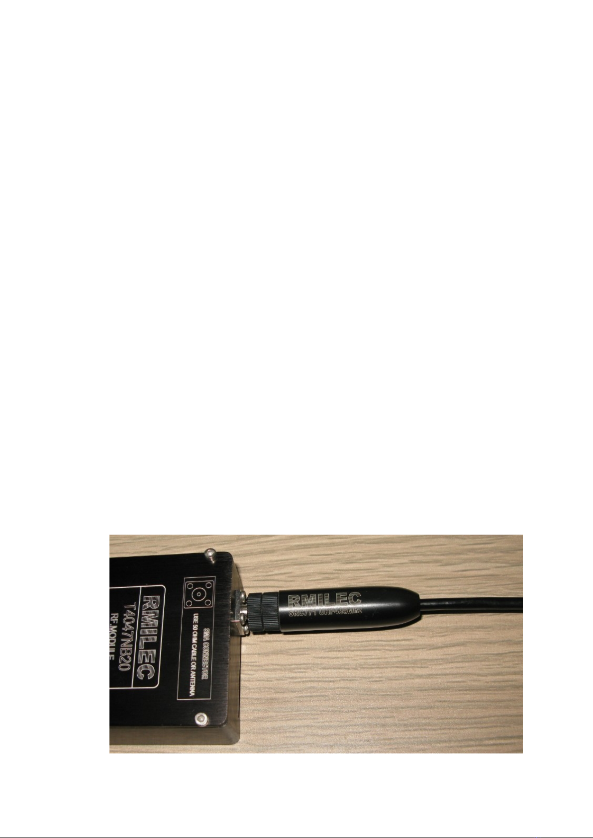
RF output
Output interface is 50 ohm SMA socket. RF socket need to be connected to the
antenna during the operation. If RF socket is open circuit or short circuit, the amplifier
will be damaged by overheated.
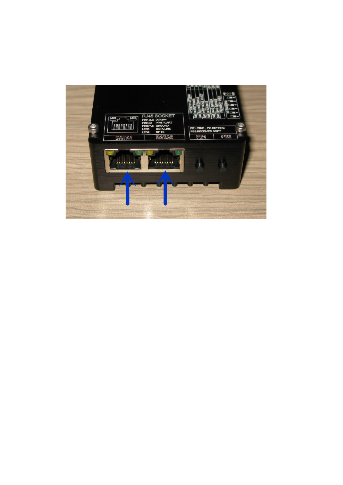
Power and Data socket
DATA1: Data and power input socket 1
Input data is PPM or UART digital signal, which can be switched through
SW3.Voltage range is 10~14VDC, typically 12VDC. Exceeding normal range of
operation will result in increasing failure rate, or even permanent damage.
DATA2: Data and power input socket 2
Functions are the same as DATA1.
Notes:
When using the PPM mode, 10CH PPM signal can be input through DATA1.
The corresponding output of the UHF receiver is 1-10CH. DATA2 can also input
10CH PPM signal, the corresponding output of the UHF receiver is 11-20CH.
When using UART digital signal, the functions of DATA1 and DATA2 are
identical, either of which can be connected with signal acquisition system and
input 20CH data.

DIP Switch
SW1 is designed for RF power selecting.
“ON” indicates high-power mode, of which output power is 5W. The RF output
warning tone is do, re, mi, fa..
“OFF” indicates low-power mode, of which output power is 2W. The RF output
warning tone is do, re, mi.
Note:
There is no warning tone of do, re, mi, or do, re, mi, fa in debug mode.
When used as a hand-held transmitter, please select low-power mode. SW1 will
directly take effect when it is set before or after power on.
SW2 is designed for Failsafe setting.
“ON” indicates disable failsafe. Servos will remain on the last position after
losing signal.
“OFF” indicates enable failsafe. After losing signal, the receiver will read out
servo position data which is previously stored in the receiver.
Note:
SW2 can only take effect when it is set before the transmitter and receiver
power on.
SW3 is designed for selecting input signal.
“ON” indicates DATA1 and DATA2 can only input PPM signal. UHF transmitter

is used for directly connecting to the remote control equipment.
“OFF” indicates DATA1 and DATA2 can only input digital signal. It is used to
connect the signal acquisition system.
Note:
When using the PPM signal, please select low power mode in order to avoid
distortion of the PPM signal and the crash of remote control equipment.SW3 can
only take effect when it is set before the transmitter power on.
SW4 is designed for debug mode.
“ON” indicates for enable the debug mode. Then the RF power amplifier will
turn off, and the RF output will be very weak. This mode is used for checking whether
the transmitting and receiving communication is normal.
“OFF” indicates for the normal mode.
Note:
SW4 can only take effect when it is set before the transmitter power on.
SW5 and SW6 are designed for select the output frequency. The frequency table
is as follow
SW5 is OFF&SW6 is OFF 435Mhz amateur bands
SW5 is OFF&SW6 is ON 445Mhz amateur bands
SW5 is ON &SW6 is OFF 455Mhz amateur bands
SW5 is ON &SW6 is ON 433Mhz ISM band
Please set the frequency according to the local law.
Note:
Changing the transmitting frequency will need the corresponding
transmitter antenna. SW5 and SW6 can only take effect before the transmitter is
power on. It is need to be rebind with the receiver again.
If you want to change the output frequency, the corresponding antenna is
needed. SW5 and SW6 would take effect when they are before the transmitter is
power on, and, the transmitter needs to be rebind with the UHF receiver.
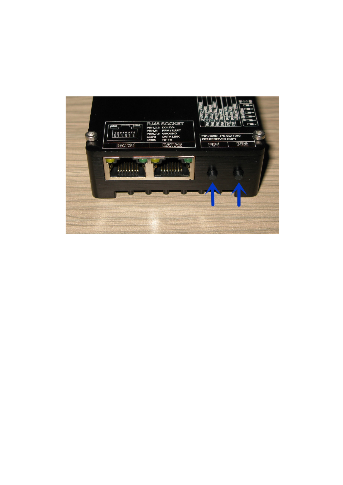
Buttons
PB1:
The transmitter will be switched to binding mode by pressing this button before
power on the transmitter.
Keeping pressing this button for 5 seconds after power on the transmitter, the
current servo position data will be stored in the receiver.
PB2: The receiver will be switched to the data copy mode by pressing the PB2
button before power on the transmitter.

RJ45 LED
LED1: Valid data input indicator,of which lighting up indicates that valid data is
being input. The data is PPM or 20CH digital data.
LED2: RF output indicator,of which lighting up indicates that the current input
data is being emitted into the air by the RF.
The meaning of Warning Tones
do, re, mi Starting to transmit in 2W mode
do, re, mi, fa Starting to transmit in 5W mode.
mi, re, do Stop transmitting
mi, do, delay, mi, do No signal being input into transmitter
do, delay, do, The transmitter is switched to the re-debug mode.
do, do, do, do ........ Transmitter input signal is lost. There is input signal
line fault.

Signal Acquisition System
Power Terminal
12V DC power input
Data Terminal

PIN1, PIN15 are ground. Connected to the negative terminal of the be-relayed
receiver.
PIN2, PIN16 are 4.8V positive power supply output, connected to the positive
power of the be-relayed receiver.
Note:
PIN1-PIN2 and PIN15-PIN16, which internally parallel, can provide two be-
relayed receiver .
Terminology:
Be-relayed receiver - This receiver: does not refer to R4047NB20, but means the
receiver which input data into the Signal Acquisition System, namely the original
receiver of the remote control equipment, the R6203SB and R6014HS, for
example.
PIN3-PIN12 are PWM input, which are used to connect with the output terminal
of the R6014HS’s PWM output. The FUTABA servo, for example, white wire of
which is PWM signal. The PWM signal acquired by PIN3-PIN12 are corresponded to
the CH1-CH10 PWM output signal of R4047NB20 receiver.
PIN17-PIN26 are PWM input, which functions the same as PIN3-PIN12.
The PWM signal acquired by PIN17-PIN26 correspond to the CH11-CH20
PWM output of R4047NB20 receiver.
PIN13 is PPM input. If be-relayed equipment has PPM output interface, such as
head tracker or the receiver with PPM output, you can use PIN13 to input signal to

avoid cumbersome wiring. The PPM indicator lamp will light up when the valid PPM
signal is detected.
Note:
PIN13 can input PPM containing 14 channels of data, while the the PPM
signal rate should be larger than 30Hz. Moreover, the PPM content should be
more than 4 channels of data, otherwise it will be considered as invalid signal or
error signal.
PIN14 is SBUS input. If you have receiver like R6203SB, you can use single
terminal such as PIN1,PIN2,PIN14 to forward 18CH. If a valid SBUS signal is
detected, SBUS LED will light up.
PIN27 is the IDLE control terminal of the transmitter. The input signal is PWM
signal. When the input pulse width more than 1.55 milliseconds, T4047NB20
transmitter will move to IDLE mode with no signal to be transmitted and IDLE LED
will light up. When the input pulse width is equal or lesser than 1.55 ms, T4047NB20
will keep transmitting with the previous frequency. If there is no signal on PIN27 ,
then there is no operation.
PIN28 is the IDLE control terminal of the transmitter. The input signal is logic
signal. If there is no load, then no operation will be conducted,and the transmitter will
be in the normal mode. When there is short circuit to GND, the transmitter will move
to IDLE mode with no signal transmitting,and the IDLE LED will light up. When
there is open circuit to GND, the transmitter will move to normal mode.
Note:
When input a mixed-signal, the PWM signal has priority over PPM, and
PPM has priority over SBUS.
For example, when SBUS and the PWM input at the same time, the
corresponding servo signal of SBUS will be replaced by PWM signal and then be
transmitted.
When there is no data input, the signal acquisition system will not output
data and the fault LED will light up . When there is any valid data input through
PWM \ PPM \ SBUS, the signal acquisition system will output data stream, and
the data output LED will light up.
If the input signal is lost, the other channels besides CH3 and CH13 will
transmit 1.5mS signal automatically. And the CH3 and CH13 will transmit
1.1mS signal.
WARNING: Please correctly set ESC or the engine throttle control direction.
1.1 ms means engine cut. This is opposite to the default direction of FUTABA
radio. If it is set incorrectly, the motor may suddenly start up under failure

condition, leading to accident. Only CH3 and CH13 can be configured to throttle
channel. If you want to use other channels to control the throttle, please handle it
with caution. You should correctly set failsafe of R4047NB20 to avoid accidents.
RJ45 ELD
LED1: no signal input. Light-up LED1 means no input signal. By this time, no
data will be output. T4047NB20 transmitter will send output regular alarm to indicate
no signal.
LED2: data output indicator. Light-up of LED2 means 20CH digital data is being
output.
Common Indicators
PPM LED: It will light up after a valid PPM signal was detected.
S.BUS LED: It will light up after a valid SBUS signal was detected.
IDLE LED: The T4047NB20 transmitter will move to IDLE mode when the
IDLE control terminal input pulse width is more than 1.55mS. By this time, IDLE
LED lights up, which means there is no signal to be transmitted.

Receiver
Receiver Pin Definitions
PIN1-PIN10 are CH1-CH10 PWM output
PIN11 is CH1-CH10 PPM output
PIN12 is CH1-CH18 SBUS output (compatible with the FUT SBUS)
PIN13-PIN22 are CH11-CH20 PWM output
PIN23 is CH11-CH20 PPM output
PIN24 is RSSI output, which the maximum current is 20mA with 50
Ohms internal resistance.

Buttons
Press BIND and power on the receiver, then it will move to binding mode or
copy mode.
Press SCAN, and power on the receiver, then it will move to the interference
scan mode.
Common Indicators
RF RX: When the receiver RX or TX (there is RF output under binding mode)
RF RX LED will light up.
DONE: It will light up when binding operation or F/S setting is completed.
ANT1: Light-up of ANT1 indicates the receiver choose ANT1 RF signal.
ANT2: Light-up of ANT2 indicates the receiver choose ANT2 RF signal.
Signal Strength Indicator
Note:
The scopes of the indication of RSSI and EMI signal are the same. When
indicate RSSI , the more LED lights the stronger signal is received and the
situation is better.
When indicate EMI, the more LED lights the stronger interference is
received and the environment worse.
LED1 - LED5 are all off: indicates that the input signal is less than-115dBm
LED1 lit: the input signal is -115dBm to -109dBm
LED2 lit: the input signal is -109dBm to -103dBm
LED3 lit: the input signal is -103dBm to -97dBm
LED4 lit: the input signal is-97dBm to -85dBm
LED5 lights up when the input signal exceeds -85dBm
The Calculation of RSSI Output Voltage
Y = -120 + X / 20;
Y: RSSI Unit is dBm
X: RSSI voltage Unit is mV.
Examples as follows:
If the measured RSSI voltage is 900mV, according to the above formula,
900/20-120 = -75, then the actual received RSSI is-75dBm.
If the measured RSSI voltage is 0.1V, according to the above formula,
100/20-120 = -115, then the actual received RSSI is-115dBm. (Minimum value)
Installation
Transmitter Installation
Control Process
Take FUTABA T12FG as example, T12FG transmits signals to R6203SB, and then
R6203SB transmits the SBUS signal to the signal acquisition system, subsequently
the signal acquisition system transmits signals to T4047NB20, following that
T4047NB20 transmits UHF RF signal to R4047NB20, and R4047NB20 output 18
channels of PWM signals to each servo.
The Installation of RF Part
The antenna can be installed directly to the transmitter's RF interface. You can
also use the RF cable with SMA terminal.

The picture above shows the use of hand-held antenna.
The picture above shows the use of car antenna(RG402 cable is recommended).
Data Interface and Power Supply Connection
The data interface is RJ45 interface, connected to the signal acquisition system
with a flat 8-pin data cable. The signal acquisition system is powered by large
capacity batteries or by a car cigarette lighter.

Powered by a Cigarette Lighter
The Connection with the be-relayed receiver
Be-relayed receiver connect the SBUS signal to the signal acquisition system, or
connect the PWM signal needed to be transmitted to any of the PWM input pin on the
acquisition box.

The picture above shows the PWM connection, in which CH12 connects to he IP
interface. the 12FG settings allows the sync-transmit of 4047NB20 system and the
12FG. Under sync-transmit, 12FG powers on coupled with the 4047NB20 starting.
And when 12FG is off, the 4047NB20 move to IDLE mode. The configuration of
12FG is as followed:
The picture above shows FUNCTION settings. CH12 is controlled by SH.
The picture above is 1-4CH Fail-Safe setted to HOLD.
The picture above is 5-8CH Fail-Safe setted to HOLD.

The picture above is 5-8CH Fail-Safe setted to HOLD, CH12 F / S +100%.
The picture above is the SBUS Connection.
NOTE:
There has to be no electronic device within 30cm of the transmitter antenna,
including the signal acquisition system and the be-relayed receiver. Because the
strong radio influence is very likely to cause signal instability and it may also cause
the malfunction or permanent damage of the be-relayed receiver.

Anti-Interference and Safe Cabling Measures
The picture above shows safe cabling method for the handheld antenna.
There is no electronic device within 30cm around the transmitter antenna.
Table of contents


