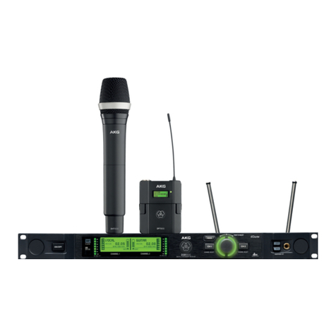
Harman AKG CMS380 User manual

CMS380 UHF WIRELESS MICROPHONE SYSTEM
USER MANUAL

2
CMS380
Symbols Used ..................................................................................................... 3
Important Safety Information ............................................................................... 4
Introduction to CMS380....................................................................................... 5
Features......................................................................................................... 5
Unpacking............................................................................................................ 6
Description .......................................................................................................... 7
SR380............................................................................................................ 7
HT380 .......................................................................................................... 10
PT380 .......................................................................................................... 12
HC380.......................................................................................................... 14
Installation & Preparation .................................................................................. 15
SR380.......................................................................................................... 15
HT380 / PT380 ............................................................................................ 16
Frequency Synchronization ............................................................................... 17
SR380.......................................................................................................... 17
HT380 / PT380 ............................................................................................ 18
Specifications .................................................................................................... 19
Troubleshooting ................................................................................................. 20
Channels & Frequencies ................................................................................... 21
CONTENTS

3
CMS380
SYMBOLS USED
The exclamation point in an equilateral triangle on the equipment indicates that it
is necessary for the user to refer to the User Manual.
In the User Manual, this symbol marks instructions that the user must follow to
ensure safe operation of the equipment.
The symbol marks important notes, hints, or explanations that make it easier to
user the equipment.
When the product reaches the end of its life, separate the housing, electronics
and cables and dispose of all components in accordance with local waste dis-
posal regulations.
The lighting flash with arrowpoint in an equilateral triangle means that there are
dangerous voltages present with the equipment.
The packaging can be recycled. Dispose the packaging in a suitable collection
system.
Disclosure for poinsonous and harmful substances or elements for the name
and content in Product:
PARTS
HAZARDOUS SUBSTANCE
Pb Hg Cd Cr6+ PBB PBDE
METAL PARTS XOOOOO
CABLES X O O O O O
“O” indicates that the concentration of the hazardous substance in homoge-
neous materials in the parts is below the relevant threshold of the SJ/T11363-
2006 standard.
“X” indicates that the concentration of the hazardous substance of at least
one of all homogeneous materials in the parts is above the relevant threshold
of the SJ/T11363-2006 standard.
CHINA-RoHS Declaration

4
CMS380
IMPORTANT SAFETY INFORMATION
1. Read and keep these instructions.
2. Heed and follow all warnings.
3. Do not use this apparatus near water.
4. Clean only with a dry cloth.
5. Do not block any ventilation openings. Install in accordance with the manufacturer’s instructions.
6. Do not install near any heat sources such as radiators, heat registers, stoves, or other apparatus
(including amplifiers) that produce heat.
7. Do not defeat the safety purpose of the polarized or grounding type plug. A polarized plug has two blades
with one wider than the other. A grounding-type plug has two blades and a third grounding prong. The
wide blade or the third prong is provided for your safety. If the provided plug does not fit into your outlet,
consult an electrician for replacement of the obsolete outlet.
8. Protect the power cord from being walked on or pinched, particularly at plugs, convenience receptacles,
and the point where they exit from the apparatus.
9. Only use attachments/accessories specified by the manufacturer.
10. Use only with a cart, stand, tripod, bracket, or table specified by the manufacturer, or sold with the
apparatus. When a cart is used, use caution when moving the cart/apparatus combination to avoid injury
from tip-over.
11. Unplug this apparatus during lightning storms or when unused for long periods of time.
12. Refer all servicing to qualified service personnel. Servicing is required when the apparatus has been
damaged in any way, such as power-supply cord or plug is damaged, liquid has been spilled or objects
have fallen into the apparatus, the apparatus has been exposed to rain or moisture, does not operate
normally, or has been dropped.
13. Use the mains plug to disconnect the apparatus from the mains.
14. WARNING: TO REDUCE THE RISK OF FIRE OR ELECTRIC SHOCK, DO NOT EXPOSE THIS APPARATUS
TO RAIN OR MOISTURE.
15. DO NOT EXPOSE THIS EQUIPMENT TO DRIPPING OR SPLASHING AND ENSURE THAT NO OBJECTS
FILLED WITH LIQUIDS, SUCH AS VASES, ARE PLACED ON THE EQUIPMENT.
16. THE MAINS PLUG OF THE POWER SUPPLY CORD SHALL REMAIN READILY OPERABLE.
SAFETY
To prevent electric shock do not remove top or button covers. No user service-
able parts inside. Refer servicing to qualified service personnel.
To completely disconnect this equipment from the AC mains, disconnect the
power supply cord plug from the AC receptacle. The mains plug of the power
supply cord shall remain readily operable.
To reduce the risk of electric shock, grounding of the centre pin of the plug
must be maintained.
Replace fuse with same type fuse and rating.
5
CMS380
INTRODUCTION TO CMS380
Thank you for purchasing AKG CMS380!
AKG CMS380 is a UHF Wireless Microphone System designed for applications where
wireless transmission is in demand. CMS380 is available in two sets:
Vocal Set Mix Set
1 x SR380 Dual-channel Receiver
2 x HT380 Hand-held Transmitter
1 x SR380 Dual-channel Receiver
1 x HT380 Hand-held Transmitter
1 x PT380 Pocket Transmitter
1 x HC380 Headset Microphone
Both the Vocal set and the Mix set include a SR380 UHF dual-channel receiver, featur-
ing interference-free and reliable transmission. SR380 offers 200 frequency band op-
tions and is capable for multi-system communications. Its Hopping Technology ensures
non-stop signal transmission during speech or performance.
The HT380 hand-held transmitter/microphone provides high and low transmission pow-
er options for applications in either small or large venues. The hand-held microphone is
unique for its auto mute function, which will put the microphone into sleep when left idle
for 15 seconds and resume active immediately when picked up.
The combination of PT380 pocket transmitter and HC380 headset microphone is meant
to free your hands. The PT380 pocket transmitter requires only a single 1.5V AA battery
to drive and has its gain individually set. The HC380 headset microphone aims not to
intrude your presentation or performance, hence, is designed in an ultra compact size
and beige colour. Besides, the headset is resistant to sweat and moisture and comfort-
able to wear for longer hours.
To make your voice or speech clear, accurate and interference-free, this is what
CMS380 Wireless Microphone System is designed for.
Features
• UHF frequency band, interference-free and reliable transmission;
• 200 frequency band options for multi-system communications;
• Advanced Hopping Technology for non-stop signal transmission;
• Infrared technology for easy & quick setup;
• Anti-collision protection;
• Auto mute puts the handheld microphone into sleep when left idle for 15 seconds;
• Precision engineered circuit for optimal acoustic performance and lower power
consumption.

6
CMS380
Please unpack and inspect your purchase package for any damage that may have
occurred during transit. If damage is found, notify the transportation company immedi-
ately. Only you can initiate a claim for shipping damage. Save the shipping carton as
evidence of damage for the shipper’s inspection.
Please check your package upon delivery by referring to the table below. In the event
that something is missing, please contact your local AKG dealer.
NO. Scope of Delivery Vocal Set Mix Set
1SR380
Dual-channel Receiver 1 1
2HT380
Hand-held Transmitter 2 1
3PT380
Pocket Transmitter x 1
4HC380
Headset Microphone x 1
5Audio Cable 1 1
6Antenna (for SR380) 2 2
7Power Adapter (for SR380) 1 1
8Mounting Bracket (for SR380) 1 1
9Mounting Ear (for SR380) 1 1
10 Mounting Plate (for SR380) 1 1
UNPACKING

7
CMS380
DESCRIPTIONS SR380
SR380 Front View
1. Volume: Rotate the knob to set output level of CH1 or CH2.
2. Up: Press the button to select transmission channel.
3. Menu: Supports short press and long press:
• Short press: Short press the button to toggle between manual tuning or auto
scan of transmission channels.
• Long press: Long press the button for 3 seconds to lock the Up/Menu/Down
buttons. “ ” will appear on the LCD Display. Long press again to unlock.
4. Down: Press the button to select transmission channel.
5. LCD Display: Shows status of CH1 and CH2: radio frequency status, audio fre-
quency status, transmission channel, transmission frequency, and output volume.
6. IR Sensor: For frequency synchronization with HT380 or PT380.
7. Antenna: Detachable antenna. Attach the UHF antennas provided.
DON’T hand hold or block this area while SR380 is working.

8
CMS380
SR380 Rear View
7. Antenna: Detachable antenna. Attach the UHF antennas provided.
DON’T hand hold or block this area while SR380 is working.
8. ON/OFF: Press the switch to turn on or off SR380.
9. 12 V DC: Connect the power adapter provided.
10. BALANCED OUT 1/2: 3-pole XLR jack. Connect a microphone input of a mixer to
this output, for example.
11. SENSITIVITY 1/2: The tap selector controls sensitivity of each channel. Use a flat
-head screwdriver to set each to desired value.
12. MIX OUT: 6.5 mm jack connector. Connect a guitar amplifier, for example.
DESCRIPTIONS SR380

9
CMS380
DESCRIPTIONS
SR380 LCD
13. Channel: The channel designated for transmitting audio signal of CH1 or CH2.
14. AF: Indicates intensity of audio signal detected.
15. RF: Indicates intensity of radio signal detected.
16. Lock Status: “ ” appears when the navigation buttons are locked through long
press the Menu button on the front panel.
17. Antenna (A/B): Shows the antenna receiving the audio signal.
18. Mute Status: “ ” appears when the transmitter, e.g. HT380 or PT380, is muted.
19. Volume: Indicates the output volume of the channel.
20. Frequency: Shows the transmission radio frequency for the channel.
SR380

10
CMS380
H L
HT380 Front View
1. Voice Pick-up: For vocal or instrument sound pick-up.
DON’T hand hold or block this area while HT380 is working.
2. IR Sensor: For frequency synchronization with SR380.
3. LCD Display: Shows status of HT380: battery level, transmission channel, au-
to-mute status.
4. Grip / Battery Compartment: Twist off to install two 1.5V AA batteries.
5. Antenna: For wireless transmission of audio signal.
DON’T hand hold or block this area while HT380 is working.
6. On/Off button: Supports short press and long press:
• Long press: Long press the button for 3 seconds to power on or off HT380.
• Short press: Short press the button for 3 times to activate or deactivate
auto-mute. “ ” appears on the LCD when auto mute is on.
Auto Mute
• When auto-mute is activated, HT380 will mute automatically when laid idle for 15
seconds.
• When HT380 is muted, simply pick it up will automatically deactivate the mute
status.
7. Transmission Power Control: Inside the Battery Compartment. Use the switch to
select appropriate transmission power of HT380.
Transmission Power
• H=50mW. Suitable for application in large venue.
• L=30mW. Suitable for application in small space.
DESCRIPTIONS HT380

11
CMS380
H L
HT380 LCD
8. Battery Level: Indicates the battery level when HT380 is powered on. Flashes
when the battery is low.
9. Channel: The transmission channel designated for HT380.
10. Auto Mute: Short press the On/Off button for 3 times to activate or deactivate
auto-mute. “ ” appears when auto mute is on.
Auto Mute
• When auto-mute is activated, HT380 will mute automatically when laid idle for 15
seconds.
• When HT380 is muted, simply pick it up will automatically deactivate the mute
status.
DESCRIPTIONS HT380

12
CMS380
PT380 Front & Top View
1. LCD Display: Shows the following information of battery level (when powered on),
transmission channel, and status (off, mute/program).
2. Belt Clip: To attach the pocket transmitter to a belt.
3. Battery Compartment: Remove the cover to install one 1.5V AA battery.
4. Antenna: Integrated flexible antenna. For wireless transmission of audio signal.
DON’T hand hold or block this area while PT380 is working.
5. IR Sensor: For frequency synchronization with SR380.
6. Audio Input Jack: Uses a 3-pole male mini XLR connector for connection with
HC380.
7. Slider Switch: The slider switch has three positions:
• OFF: Turns off the power supply of PT380.
• MUTE/PRG: Prepare for frequency tuning or mute PT380.
• ON: Turns on PT380 for audio signal transmission.
Before setting up transmission channel of PT380, please ensure the Slider
Swith is positioned to “MUTE/PRG” .
DESCRIPTIONS PT380

13
CMS380
DESCRIPTIONS PT380
8. Gain Control: Inside the Battery Compartment. Set to desired level using the
battery cover pin-out or a flat-head screwdriver.
PT380 LCD
9. Channel: The transmission channel designated for PT380.
10. Mute Status: Shows mute status of PT380. “ ” appears when PT380 is
muted through the MUTE/PRG Slider Switch.
11. Battery Level: Indicates the battery level when PT380 is powered on. Flashes
when the battery is low.

14
CMS380
1. Audio Output Jack: Uses a 3-pole mini female XLR connector for connection with
PT380.
2. Ear Hookers: To wear the headset to your head.
3. Voice Pick-up: For voice picking up.
DON’T hand hold or block this area while HC380 is working.
DESCRIPTIONS HC380

15
CMS380
INSTALLATION & PREPARATION SR380
Please follow the guidance to install your SR380.
1. Place SR380 on the flat and stable work-desk or mount it onto an equipment rack
(refer to the image below for rack-mounting).
RACK-MOUNTING OF SR380
Mounting 1xSR380
Mounting 2xSR380
将SR380固定于机架
固定1台SR380
固定2台SR380
2. Attach the antennas provided to SR380.
3. Connect the power adapter provided to SR380.
4. Connect SR380’s BALANCE OUT 1/2 or MIX OUT to the downstream audio de-
vice, e.g. mixer or amplifier.
5. Switch on SR380.
Ensure volume of all audio devices, including SR380, is turned to the lowest
before you connect them up.

16
CMS380
Please follow the guidance below to prepare your HT380 or PT380.
To prepare HT380:
1. Insert two pieces of 1.5V
AA batteries.
2. Select appropriate trans-
mission power.
3. Long press the On/Off
button to power on.
To prepare PT380:
1. Insert one piece of 1.5V AA
battery.
2. Set appropriate gain level
using the battery cover
pin-out.
3. Connect HC380 to PT380.
4. Set the slider switch to
appropriate position.
INSTALLATION & PREPARATION HT380 / PT380
1.5V AA
x 1
1.5V AA
x 2

17
CMS380
Please follow instructions below to set up transmission channel between SR380 and
HT380 or PT380.
1. Set transmission channel for SR380.
Transmission frequency of SR380 can be set up via manual tuning or auto scan.
A) Manual Tuning:
Simply short-press the Up or Down
button to select the channel.
B) Auto Scan:
1) Short press the Menu button. 2) Then the LCD shows “CH SCA”.
3) Short press the Up or Down button
to start auto scan.
4) The valid and usable transmission channel
will flash three times. Otherwise, repeat
step 1-3 till the result channel is valid.
FREQUENCY SYNCHRONIZATION SR380

18
CMS380
2. Synchronize transmission channel for HT380 or PT380.
1) Long press the Up button of SR380. 2)The LCD flashes “ ”.
3) Power on HT380 or PT380. Position their IR sensor next to IR sensor of SR380.
When frequency synchronization is done, HT380 or PT380 will share the same trans-
mission channel with SR380.
Before setting up transmission channel of PT380, please ensure the Slider
Switch is positioned to “MUTE/PRG” .
3. Slightly turn up output volume using the Volume Knob of SR380. Now you
can start the singing or speech.
FREQUENCY SYNCHRONIZATION HT380 / PT380

19
CMS380
SPECIFICATIONS
HC380
Frequency Response 20 to 18K Hz
Polar Pattern Cardioid
Sensitivity @ 1KHz -42 ± 3 dB
Impedance 2,200 ohm
Connector Mini XLR
Net Weight 19 g
HT380
Switching Bandwidth 30 MHz
Modulation FM
RF Output Power 30/50 mW
Spurious Suppression -60 dB
Antenna Built-in antenna
Frequency Response 20 to 18K Hz
THD typ. ≤0.5%
S/N Ratio (A-weighted) typ. 105 dB(A)
Battery Life > 8 hrs
Size 257 mm x Ø37 mm
Net Weight 324.5 g
SR380
Carrier Frequency 740 - 770 MHz
Switching Bandwidth 30 MHz
Modulation FM
Spurious Suppression ≥75 dB
Antenna External antenna
Frequency Response 20 to 18K Hz
THD typ. ≤0.5%
S/N Ratio (A-weighted) typ. 105 dB(A)
Power Supply DC 12 V / 500 mA
Size 210 mm x 194 mm x 43
mm
Net Weight 1,070 g
PT380
Switching Bandwidth 30 MHz
Modulation FM
RF Output Power 50 mW
Spurious Suppression -60 dB
Antenna External antenna
Frequency Response 20 to 18K Hz
THD typ. ≤0.5%
S/N Ratio (A-weighted) typ. 105 dB(A)
Battery Life > 4 hrs
Size 60 mm x 73.5 mm x
30 mm
Net Weight 65 g

20
CMS380
TROUBLESHOOTING
Problem Possible cause Remedy
No sound
AC adapter is not connected to receiver
and/or power outlet.
Connect AC adapter to receiver and/or
power outlet.
Receiver is OFF. Push ON/OFF switch to switch receiver ON.
Receiver is not connected to mixer or
amplifier.
Connect receiver output to mixer or amplifier
input.
Volume knob on receiver is at zero. Turn up Volume knob.
Transmitter has a different frequency
range or is tuned to a different frequency
from the receiver.
Use a transmitter with the same frequency
range as the receiver or tune both to the
same frequency.
Transmitter on/off switch is at "OFF" or
"MUTE".
Set transmitter on/off switch to "ON".
Transmitter batteries are not inserted
properly.
Insert batteries conforming to "+" and "-"
marks.
Transmitter batteries are flat. Replace transmitter batteries.
Transmitter is too far away from receiver. Move closer to receiver.
Obstructions between transmitter and
receiver.
Remove obstructions.
No line of sight between transmitter and
receiver.
Avoid spots where you cannot see receiver.
Receiver is too close to metal objects. Remove interfering objects or move receiver
away from them.
Noise, crack-
ling, unwanted
signals
Antenna position. Move receiver to a different location.
Interference from other wireless systems,
TV, radio, walkie-talkies, or defective
electrical appliances or installations.
Switch off interference sources or defective
appliances or use a CMS380 system tuned
to a different frequency; have electrical
installation checked.
Distortion
GAIN control is set too high or too low. Turn GAIN control up or down until distortion
goes away.
Interference from other wireless systems,
TV, radio, walkie-talkies, or defective
electrical appliances or installations.
Switch off interference sources or defective
appliances or use a CMS380 tuned to a dif-
ferent frequency; have electrical installation
checked.
Antenna position. Move receiver to a different location. If dead
spots persist, mark and avoid them.
Table of contents
Other Harman Microphone System manuals

Harman
Harman AKG DMM12 User manual

Harman
Harman AKG WMS420 User manual

Harman
Harman AKG DMS100 User manual

Harman
Harman AKG WMS420 User manual

Harman
Harman AKG WMS420 User manual

Harman
Harman AKG KM200 User manual

Harman
Harman JBL QUANTUM Stream Talk User manual

Harman
Harman JBL VM200 User manual

Harman
Harman JBL VM300 User manual

Harman
Harman AKG DMS800 User manual