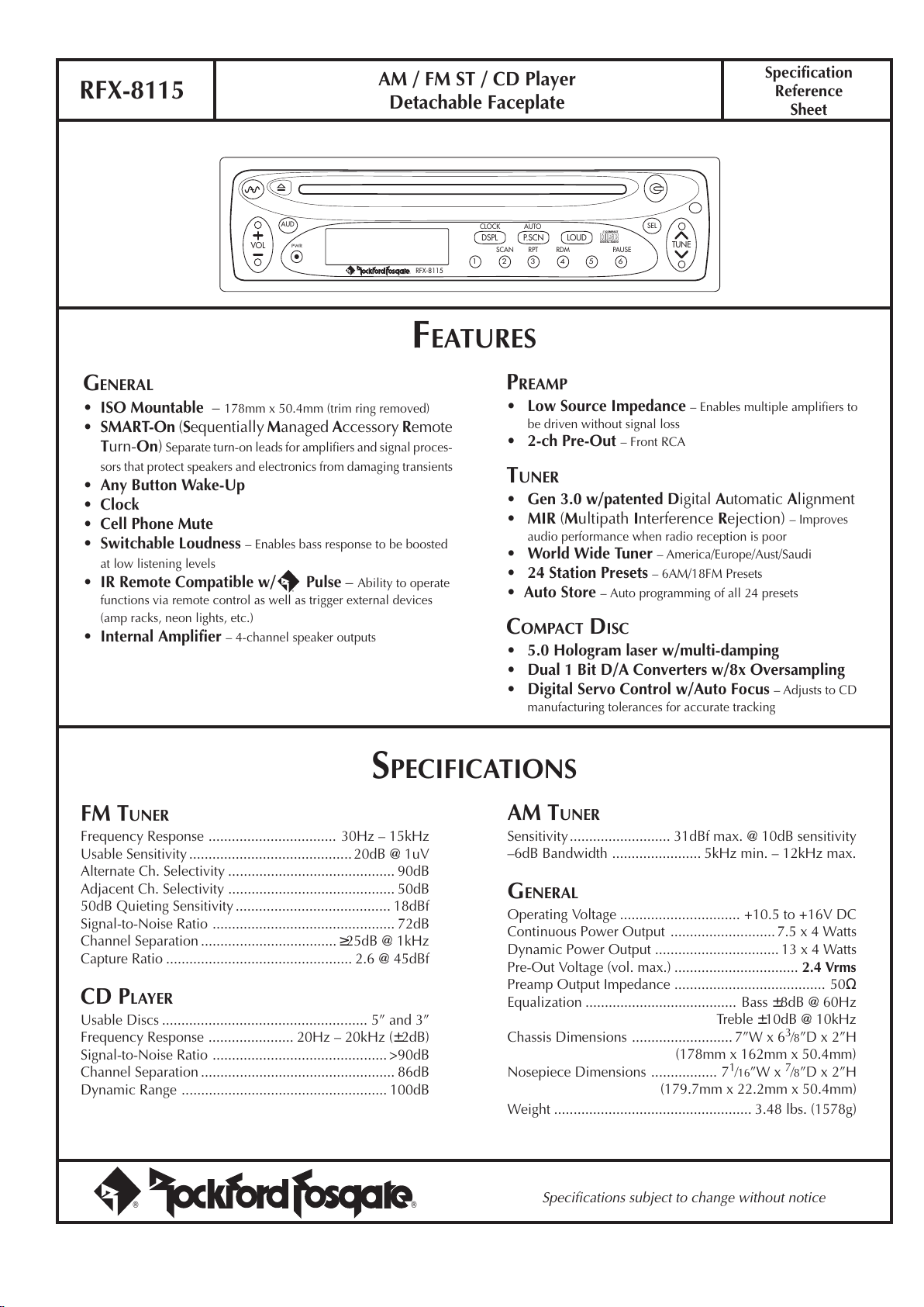
AM / FM ST / CD Player
Detachable Faceplate
RFX-8115 Specification
Reference
Sheet
GENERAL
•ISO Mountable – 178mm x 50.4mm (trim ring removed)
•SMART-On (Sequentially Managed Accessory Remote
Turn-On) Separate turn-on leads for amplifiers and signal proces-
sors that protect speakers and electronics from damaging transients
•Any Button Wake-Up
•Clock
•Cell Phone Mute
•Switchable Loudness – Enables bass response to be boosted
at low listening levels
•IR Remote Compatible w/ Pulse – Ability to operate
functions via remote control as well as trigger external devices
(amp racks, neon lights, etc.)
•Internal Amplifier – 4-channel speaker outputs
FEATURES
PREAMP
•Low Source Impedance – Enables multiple amplifiers to
be driven without signal loss
•2-ch Pre-Out – Front RCA
TUNER
•Gen 3.0 w/patented Digital Automatic Alignment
•MIR (Multipath Interference Rejection) – Improves
audio performance when radio reception is poor
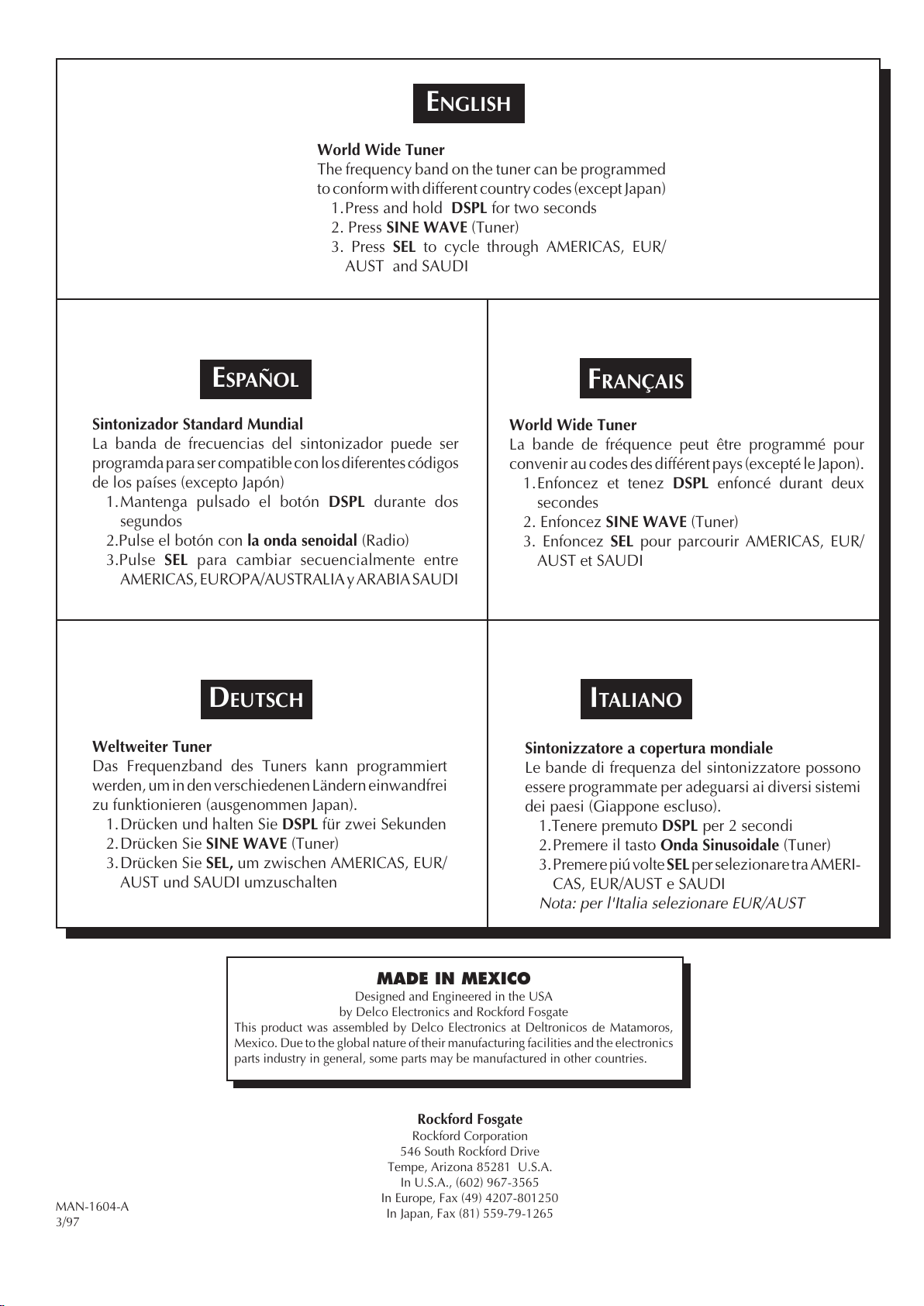
•World Wide Tuner – America/Europe/Aust/Saudi
•24 Station Presets – 6AM/18FM Presets
•Auto Store – Auto programming of all 24 presets
COMPACT DISC
•5.0 Hologram laser w/multi-damping
•Dual 1 Bit D/A Converters w/8x Oversampling
•Digital Servo Control w/Auto Focus – Adjusts to CD
manufacturing tolerances for accurate tracking
SPECIFICATIONS
FM TUNER
Frequency Response ................................. 30Hz – 15kHz
Usable Sensitivity..........................................20dB @ 1uV
Alternate Ch. Selectivity ........................................... 90dB
Adjacent Ch. Selectivity ........................................... 50dB
50dB Quieting Sensitivity........................................ 18dBf
Signal-to-Noise Ratio ............................................... 72dB
Channel Separation ...................................≥25dB @ 1kHz
Capture Ratio ................................................ 2.6 @ 45dBf
CD PLAYER
Usable Discs ..................................................... 5” and 3”
Frequency Response ...................... 20Hz – 20kHz (±2dB)
Signal-to-Noise Ratio ............................................. >90dB
Channel Separation .................................................. 86dB
Dynamic Range ..................................................... 100dB
AM TUNER
Sensitivity.......................... 31dBf max. @ 10dB sensitivity
–6dB Bandwidth ....................... 5kHz min. – 12kHz max.
GENERAL
Operating Voltage ............................... +10.5 to +16V DC
Continuous Power Output ...........................7.5 x 4 Watts
Dynamic Power Output ................................ 13 x 4 Watts
Pre-Out Voltage (vol. max.) ................................ 2.4 Vrms
Preamp Output Impedance ....................................... 50Ω
Equalization ....................................... Bass ±8dB @ 60Hz
Treble ±10dB @ 10kHz
Chassis Dimensions .......................... 7”W x 63⁄8”D x 2”H
(178mm x 162mm x 50.4mm)
Nosepiece Dimensions ................. 71⁄16”W x 7⁄8”D x 2”H
(179.7mm x 22.2mm x 50.4mm)
Weight ................................................... 3.48 lbs. (1578g)
®®
Specifications subject to change without notice
®
RFX-8115
®®
AUD SEL
6
RDMRPTSCAN PAUSE
43 521
P.SCN LOUDDSPL
CLOCK
PWR
AUTO
VOL TUNE
COMPACT
DIGITAL AUDIO