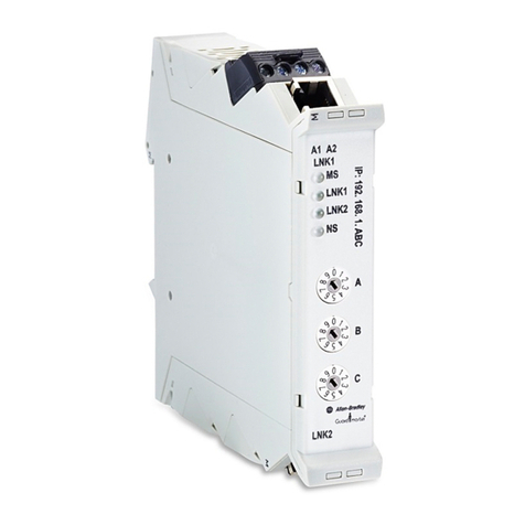
Rockwell Automation AllenBradley 432ES-IG3 User manual

User Manual Original Instructions
GuardLink EtherNet/IP
Interface
Catalog Number 432ES-IG3

2Rockwell Automation Publication 432ES-UM001A-EN-P - September 2022
GuardLink EtherNet/IP Interface User Manual
Important User Information
Read this document and the documents listed in the additional resources section about installation, configuration, and
operation of this equipment before you install, configure, operate, or maintain this product. Users are required to familiarize
themselves with installation and wiring instructions in addition to requirements of all applicable codes, laws, and standards.
Activities including installation, adjustments, putting into service, use, assembly, disassembly, and maintenance are required to
be carried out by suitably trained personnel in accordance with applicable code of practice.
If this equipment is used in a manner not specified by the manufacturer, the protection provided by the equipment may be
impaired.
In no event will Rockwell Automation, Inc. be responsible or liable for indirect or consequential damages resulting from the use
or application of this equipment.
The examples and diagrams in this manual are included solely for illustrative purposes. Because of the many variables and
requirements associated with any particular installation, Rockwell Automation, Inc. cannot assume responsibility or liability for
actual use based on the examples and diagrams.
No patent liability is assumed by Rockwell Automation, Inc. with respect to use of information, circuits, equipment, or software
described in this manual.
Reproduction of the contents of this manual, in whole or in part, without written permission of Rockwell Automation, Inc., is
prohibited.
Throughout this manual, when necessary, we use notes to make you aware of safety considerations.
These labels may also be on or inside the equipment to provide specific precautions.
The following icon may appear in the text of this document.
WARNING: Identifies information about practices or circumstances that can cause an explosion in a hazardous environment,
which may lead to personal injury or death, property damage, or economic loss.
ATTENTION: Identifies information about practices or circumstances that can lead to personal injury or death, property
damage, or economic loss. Attentions help you identify a hazard, avoid a hazard, and recognize the consequence.
IMPORTANT Identifies information that is critical for successful application and understanding of the product.
SHOCK HAZARD: Labels may be on or inside the equipment, for example, a drive or motor, to alert people that dangerous
voltage may be present.
BURN HAZARD: Labels may be on or inside the equipment, for example, a drive or motor, to alert people that surfaces may
reach dangerous temperatures.
ARC FLASH HAZARD: Labels may be on or inside the equipment, for example, a motor control center, to alert people to
potential Arc Flash. Arc Flash will cause severe injury or death. Wear proper Personal Protective Equipment (PPE). Follow ALL
Regulatory requirements for safe work practices and for Personal Protective Equipment (PPE).
Identifies information that is useful and can help to make a process easier to do or easier to understand.

Rockwell Automation Publication 432ES-UM001A-EN-P - September 2022 3
Table of Contents
About This Publication . . . . . . . . . . . . . . . . . . . . . . . . . . . . . . . . . . . . . . . . . . . 7
Who Should Use this Manual. . . . . . . . . . . . . . . . . . . . . . . . . . . . . . . . . . . . . . 7
Definitions . . . . . . . . . . . . . . . . . . . . . . . . . . . . . . . . . . . . . . . . . . . . . . . . . . . . . . 8
Additional Resources . . . . . . . . . . . . . . . . . . . . . . . . . . . . . . . . . . . . . . . . . . . . . 9
Chapter 1
Introduction Overview . . . . . . . . . . . . . . . . . . . . . . . . . . . . . . . . . . . . . . . . . . . . . . . . . . . . . . . 11
Requirements . . . . . . . . . . . . . . . . . . . . . . . . . . . . . . . . . . . . . . . . . . . . . . . 12
Automatic Diagnostics . . . . . . . . . . . . . . . . . . . . . . . . . . . . . . . . . . . . . . . 12
Physical Features . . . . . . . . . . . . . . . . . . . . . . . . . . . . . . . . . . . . . . . . . . . . . . . 12
Modes of Operation. . . . . . . . . . . . . . . . . . . . . . . . . . . . . . . . . . . . . . . . . . 13
System Design. . . . . . . . . . . . . . . . . . . . . . . . . . . . . . . . . . . . . . . . . . . . . . . . . . 13
GuardLink Components. . . . . . . . . . . . . . . . . . . . . . . . . . . . . . . . . . . . . . 13
Taps . . . . . . . . . . . . . . . . . . . . . . . . . . . . . . . . . . . . . . . . . . . . . . . . . . . . . . . . . . . 13
Tap Connections . . . . . . . . . . . . . . . . . . . . . . . . . . . . . . . . . . . . . . . . . . . . 14
Tap Cabling . . . . . . . . . . . . . . . . . . . . . . . . . . . . . . . . . . . . . . . . . . . . . . . . . 14
Tap Replacement . . . . . . . . . . . . . . . . . . . . . . . . . . . . . . . . . . . . . . . . . . . . 16
Channel Order . . . . . . . . . . . . . . . . . . . . . . . . . . . . . . . . . . . . . . . . . . . . . . 16
Terminator . . . . . . . . . . . . . . . . . . . . . . . . . . . . . . . . . . . . . . . . . . . . . . . . . . . . . 17
Commissioning Example. . . . . . . . . . . . . . . . . . . . . . . . . . . . . . . . . . . . . 18
Chapter 2
Mechanical Installation Approximate Dimensions. . . . . . . . . . . . . . . . . . . . . . . . . . . . . . . . . . . . . . . . 19
High Vibration Areas . . . . . . . . . . . . . . . . . . . . . . . . . . . . . . . . . . . . . . . . 19
Cable Clearance. . . . . . . . . . . . . . . . . . . . . . . . . . . . . . . . . . . . . . . . . . . . . . . . . 20
Chapter 3
Electrical Connections Wiring . . . . . . . . . . . . . . . . . . . . . . . . . . . . . . . . . . . . . . . . . . . . . . . . . . . . . . . . . 21
Power Supply . . . . . . . . . . . . . . . . . . . . . . . . . . . . . . . . . . . . . . . . . . . . . . . . . . . 23
Multiple Power Supplies . . . . . . . . . . . . . . . . . . . . . . . . . . . . . . . . . . . . . . . . . 24
Chapter 4
Add the Network Interface
Module
Set the IP Address. . . . . . . . . . . . . . . . . . . . . . . . . . . . . . . . . . . . . . . . . . . . . . . 25
Requirements . . . . . . . . . . . . . . . . . . . . . . . . . . . . . . . . . . . . . . . . . . . . . . . 25
Alternative Methods to Set the IP Address. . . . . . . . . . . . . . . . . . . . . . 26
Update Firmware . . . . . . . . . . . . . . . . . . . . . . . . . . . . . . . . . . . . . . . . . . . . . . . 26
Before You Update. . . . . . . . . . . . . . . . . . . . . . . . . . . . . . . . . . . . . . . . . . . 26
Update Firmware . . . . . . . . . . . . . . . . . . . . . . . . . . . . . . . . . . . . . . . . . . . . 28
Install the Profile. . . . . . . . . . . . . . . . . . . . . . . . . . . . . . . . . . . . . . . . . . . . . . . . 30
Add the Network Interface Module to a Controller Project . . . . . . . . . . 30
View Module Profile Properties . . . . . . . . . . . . . . . . . . . . . . . . . . . . . . . 31
General Page . . . . . . . . . . . . . . . . . . . . . . . . . . . . . . . . . . . . . . . . . . . . . . . . 32
Connection Page . . . . . . . . . . . . . . . . . . . . . . . . . . . . . . . . . . . . . . . . . . . . 35
Safety Page . . . . . . . . . . . . . . . . . . . . . . . . . . . . . . . . . . . . . . . . . . . . . . . . . 36
Module Info Page. . . . . . . . . . . . . . . . . . . . . . . . . . . . . . . . . . . . . . . . . . . . 39
Channels Page . . . . . . . . . . . . . . . . . . . . . . . . . . . . . . . . . . . . . . . . . . . . . . 40

4Rockwell Automation Publication 432ES-UM001A-EN-P - September 2022
Table of Contents
Internet Protocol Page . . . . . . . . . . . . . . . . . . . . . . . . . . . . . . . . . . . . . . . 41
Port Configuration Page . . . . . . . . . . . . . . . . . . . . . . . . . . . . . . . . . . . . . 42
Network Page . . . . . . . . . . . . . . . . . . . . . . . . . . . . . . . . . . . . . . . . . . . . . . . 43
Time Sync Page. . . . . . . . . . . . . . . . . . . . . . . . . . . . . . . . . . . . . . . . . . . . . . 44
Append GuardLink Nodes . . . . . . . . . . . . . . . . . . . . . . . . . . . . . . . . . . . . . . . 44
Append GuardLink Nodes to the Network Interface Module . . . . . 44
Manual Method . . . . . . . . . . . . . . . . . . . . . . . . . . . . . . . . . . . . . . . . . . . . . 45
Discover Modules Method . . . . . . . . . . . . . . . . . . . . . . . . . . . . . . . . . . . . 45
Chapter 5
Modify GuardLink Topology Overview . . . . . . . . . . . . . . . . . . . . . . . . . . . . . . . . . . . . . . . . . . . . . . . . . . . . . . . 49
Online Node Changes . . . . . . . . . . . . . . . . . . . . . . . . . . . . . . . . . . . . . . . . 49
Controller Online . . . . . . . . . . . . . . . . . . . . . . . . . . . . . . . . . . . . . . . . . . . . 49
Safety Locked or Unlocked. . . . . . . . . . . . . . . . . . . . . . . . . . . . . . . . . . . . 49
Node Tags Used in Routines . . . . . . . . . . . . . . . . . . . . . . . . . . . . . . . . . . 50
Insert a Node . . . . . . . . . . . . . . . . . . . . . . . . . . . . . . . . . . . . . . . . . . . . . . . . . . . 50
Change a Node . . . . . . . . . . . . . . . . . . . . . . . . . . . . . . . . . . . . . . . . . . . . . . . . . 57
Append a Node . . . . . . . . . . . . . . . . . . . . . . . . . . . . . . . . . . . . . . . . . . . . . . . . . 61
Delete a Node. . . . . . . . . . . . . . . . . . . . . . . . . . . . . . . . . . . . . . . . . . . . . . . . . . . 63
Remove the Last Node . . . . . . . . . . . . . . . . . . . . . . . . . . . . . . . . . . . . . . . 63
Chapter 6
Controller Tags Interface Input Tags . . . . . . . . . . . . . . . . . . . . . . . . . . . . . . . . . . . . . . . . . . . . 67
Tap Input Tags. . . . . . . . . . . . . . . . . . . . . . . . . . . . . . . . . . . . . . . . . . . . . . . . . . 71
Guard Locking Input Tags . . . . . . . . . . . . . . . . . . . . . . . . . . . . . . . . . . . . . . . 72
Tap and Guard Locking Output Tags. . . . . . . . . . . . . . . . . . . . . . . . . . . . . . 75
Chapter 7
Troubleshooting Diagnostic Status Indicators . . . . . . . . . . . . . . . . . . . . . . . . . . . . . . . . . . . . . 77
Faults . . . . . . . . . . . . . . . . . . . . . . . . . . . . . . . . . . . . . . . . . . . . . . . . . . . . . . . . . . 78
Controller Organizer Faults . . . . . . . . . . . . . . . . . . . . . . . . . . . . . . . . . . 78
Channel Faults . . . . . . . . . . . . . . . . . . . . . . . . . . . . . . . . . . . . . . . . . . . . . . 79
Node Faults . . . . . . . . . . . . . . . . . . . . . . . . . . . . . . . . . . . . . . . . . . . . . . . . . . . . 79
Fault Status Indicators . . . . . . . . . . . . . . . . . . . . . . . . . . . . . . . . . . . . . . . 79
All Nodes Faulted . . . . . . . . . . . . . . . . . . . . . . . . . . . . . . . . . . . . . . . . . . . . 80
Verify Module Properties . . . . . . . . . . . . . . . . . . . . . . . . . . . . . . . . . . . . . . . . 80
Verify Device on the Network . . . . . . . . . . . . . . . . . . . . . . . . . . . . . . . . . . . . 82
Appendix A
Specifications General Specifications. . . . . . . . . . . . . . . . . . . . . . . . . . . . . . . . . . . . . . . . . . . 85
Environmental Specifications . . . . . . . . . . . . . . . . . . . . . . . . . . . . . . . . . . . . 85
Catalog Number Explanation . . . . . . . . . . . . . . . . . . . . . . . . . . . . . . . . . . . . 86
Appendix B
Certifications and Directives Agency and Directive Marks . . . . . . . . . . . . . . . . . . . . . . . . . . . . . . . . . . . . . 87
Declaration of Conformity . . . . . . . . . . . . . . . . . . . . . . . . . . . . . . . . . . . . . . . 88
CE Conformity . . . . . . . . . . . . . . . . . . . . . . . . . . . . . . . . . . . . . . . . . . . . . . 88

Rockwell Automation Publication 432ES-UM001A-EN-P - September 2022 5
Table of Contents
UKCA Conformity . . . . . . . . . . . . . . . . . . . . . . . . . . . . . . . . . . . . . . . . . . . 88
SIL Rating. . . . . . . . . . . . . . . . . . . . . . . . . . . . . . . . . . . . . . . . . . . . . . . . . . . . . . 88
Performance Level/Category . . . . . . . . . . . . . . . . . . . . . . . . . . . . . . . . . . . . . 89
EMC Directive . . . . . . . . . . . . . . . . . . . . . . . . . . . . . . . . . . . . . . . . . . . . . . . . . . 89
Appendix C
Safety Statements CIP Safety Devices . . . . . . . . . . . . . . . . . . . . . . . . . . . . . . . . . . . . . . . . . . . . . . 91
Appendix D
Uninstall the Logix Designer
Application Module Profile
Instructions . . . . . . . . . . . . . . . . . . . . . . . . . . . . . . . . . . . . . . . . . . . . . . . . . . . . 93
Appendix E
Configure Automatic
Diagnostics
Automatic Diagnostics on PanelView 5000 Display. . . . . . . . . . . . . . . . . 97
Index . . . . . . . . . . . . . . . . . . . . . . . . . . . . . . . . . . . . . . . . . . . . . . . . . . . . . . . 101

6Rockwell Automation Publication 432ES-UM001A-EN-P - September 2022
Table of Contents
Notes:

Rockwell Automation Publication 432ES-UM001A-EN-P - September 2022 7
Preface
About This Publication This manual is a reference guide for the 432ES-IG3 EtherNet/IP™
Communications Module for the 432ES-IG3 GuardLink® Network Interface
Module.
This publication describes the procedures to install, wire, configure, and
troubleshoot the 432ES-IG3 GuardLink network interface module. You must be
familiar with the following:
• Use of a safety controller in a Logix 5000® control system.
• Use of safety systems.
• Use of the Studio 5000® Logix and View Designer application
environment.
• Knowledge of applicable regulatory standards.
Who Should Use this Manual Use this manual to design, install, program, or troubleshoot systems that use
the 432ES-IG3 GuardLink EtherNet/IP network interface module.
You are required to have a basic understanding of electrical circuitry and
familiarity with safety-related control systems. If you do not, obtain the proper
training before using this product.
ATTENTION: Personnel who are responsible for the design, application, and
maintenance of safety-related programmable electronic systems (PES) must
be aware of the safety requirements in the application of the system.
Personnel must also be trained in the use of the system.
IMPORTANT Read and thoroughly understand the manual before installing or
operating a system that contains this device.

8Rockwell Automation Publication 432ES-UM001A-EN-P - September 2022
Preface
Definitions The Industrial Automation Glossary (publication AG-7.1) contains terms and
abbreviations that Rockwell Automation uses to describe industrial
automation systems. Table 1 lists specific terms and abbreviations that are
used in this manual.
Table 1 - Terms and Abbreviations
Term Description
AOP Add-on Profile - A Logix Designer application file that facilitates the implementation of
the 432ES. This term is also known as the module profile.
CIP Common Industrial Protocol - An industrial communication protocol that Logix 5000-
based automation systems use on Ethernet, ControlNet®, and DeviceNet®
communication networks.
CIP Safety Safety certified version of CIP™.
Client The client is a GuardLink-enabled device that connects into one of the GuardLink
circuit channels of the 432ES-IG3 network interface module. Each client is known as a
node.
DHCP Dynamic Host Configuration Protocol - A network management protocol that Internet
Protocol networks use to dynamically assign an IP address and other network
configuration parameters to each device on a network.
FW Firmware revision level.
GuardLink circuit Includes all hardware that connects to one channel of the 432ES. This hardware
includes the cables, taps, safety devices, and the terminator.
HI The on-state of the output of a logic block, or the state of an input to a logic block, or a
voltage level that is above the turn-on threshold. HI is equivalent to a Boolean value of
1.
HMI Human Machine Interface - A Rockwell Automation® product in the PanelView™ family.
Host The host is the 432ES-IG3 network interface module.
HW Hardware revision level.
LO Logic off-state or a voltage level below the turn-off threshold. LO is equivalent to a
Boolean value of 0.
MAC ID Media Access Control Identification Number - An Ethernet device on a network is
assigned a unique physical (hardware) number. This number must associate with the
IP address that is assigned to the device for proper communication.
NC No connection.
Node A GuardLink-enabled device that is installed in a GuardLink circuit. Up to 32 nodes can
connect to a circuit. The nodes are numbered from 0 to 31.
Operational state All nodes on the GuardLink channel are safety valid, and the safety Status tag for the
channel is set to a value of 1.
OSSD
Output Signal Switching Device - Typically, OSSD is a pair of solid-state signals that are
connected to a DC source supply. The signals are tested for short circuits to the DC
power supply, to the DC common, and between the two signals.
The 432ES-IG3 network interface module does not have OSSD outputs because the
safety status is transmitted over the Ethernet network. In the controller input tags, the
SIL 3 rated signal for the safety output on each channel is called Status.
PFHd The probability of failure to danger per hour.
PLC (PAC) A programmable logic controller or a programmable automation controller.
Reaction time The input reaction time is the time from when the signal changes on an input terminal
to when safety data is sent to the GuardLogix® controller.
Response time Describes the time between the initial demand that is placed on a safety device/
system, to the time when its output changes to a safe state.
Safe state One or more nodes on the GuardLink channel are not safety valid, and the safety Status
tag for the channel is set to a value of 0.
Safety valid The safety circuit receives input signals that satisfy its requirements to allow
transition to an operational state.
Tap
A tap connects a safety device to the GuardLink circuit. GuardLink-enabled taps are
nodes on the GuardLink circuit. Passive taps are not GuardLink-enabled and therefore
must connect to a GuardLink-enabled device to be considered as a node on the
GuardLink circuit. A tap is not considered as a node when the tap is a passive or
passive power tap with a shorting plug.
Rockwell Automation Publication 432ES-UM001A-EN-P - September 2022 9
Preface
Additional Resources These documents contain additional information concerning related products
from Rockwell Automation.
You can view or download publications at rok.auto/literature.
Resource Description
ControlLogix System Selection Guide, publication 1756-SG001 Provides information to help you select a ControlLogix® system.
ControlLogix 5580 and GuardLogix 5580 Controllers User Manual, publication
1756-UM543 Provides information to help you design a system, operate a ControlLogix or
GuardLogix-based controller system, and develop applications.
Guardmaster DGSafety Relay and GuardLink System User Manual, publication
440R-UM015 Provides a detailed description of the GuardLink system when connected to the DG safety
relay.
GuardLink EtherNet/IP Network Interface Installation Instructions,
publication 432ES-IN001 Describes how to install a 432ES-IG3 network interface module.
ControlFLASH Plus Quick Start Guide, publication CFP-QS001 Describes how to use the ControlFLASH Plus™ software to upgrade device firmware.
EtherNet/IP Network Devices User Manual, publication ENET-UM006 Describes how to configure and use EtherNet/IP devices to communicate on the EtherNet/IP
network.
Ethernet Reference Manual, publication ENET-RM002 Describes basic Ethernet concepts, infrastructure components, and infrastructure features.
Ethernet Media Specifications Technical Data, publication 1585-TD001 Provides technical specifications for Ethernet media cables and accessories.
System Security Design Guidelines Reference Manual,
publication SECURE-RM001
Provides guidance on how to conduct security assessments, implement Rockwell
Automation products in a secure system, harden the control system, manage user access,
and dispose of equipment.
Industrial Components Preventive Maintenance, Enclosures, and Contact
Ratings Specifications, publication IC-TD002 Provides a quick reference tool for Allen-Bradley industrial automation controls and
assemblies.
Safety Guidelines for the Application, Installation, and Maintenance of
Solid-state Control, publication SGI-1.1
Designed to harmonize with NEMA Standards Publication No. ICS 1.1-1987 and provides
general guidelines for the application, installation, and maintenance of solid-state control in
the form of individual devices or packaged assemblies incorporating solid-state
components.
Industrial Automation Wiring and Grounding Guidelines, publication 1770-4.1 Provides general guidelines for installing a Rockwell Automation industrial system.
Product Certifications website, rok.auto/certifications. Provides declarations of conformity, certificates, and other certification details.

10 Rockwell Automation Publication 432ES-UM001A-EN-P - September 2022
Preface
Notes:

Rockwell Automation Publication 432ES-UM001A-EN-P - September 2022 11
Chapter 1
Introduction
Overview A GuardLink® system is a collection of components to simplify a series
connection of safety devices while achieving the highest industrial safety
rating. The system has these important features:
• Simplifies the connection of series connected safety devices.
• Facilitates the scalability of the safety series connections.
• Provides diagnostic information about each device in the system without
having to run a separate status wire back to the machine control system.
• Allows the simultaneous or individual lock and unlock of guard locking
interlocks in the series connected system. No need for an additional wire
from the machine control system to lock and unlock the safety gate.
• Helps ease communication to the machine control system over
EtherNet/IP™. Communication includes sending non-safety commands
to devices and receiving status information back from the safety devices.
Figure 1 shows a typical safety system that uses the 432ES-IG3 network
interface module. A typical system consists of an HMI, a GuardLogix®
controller, the 432ES-IG3 GuardLink EtherNet/IP network interface module,
and a series connection of safety devices, which connect to the interface
through taps in a trunk and drop network configuration.
The GuardLogix controller and PanelView™ reside in an environmentally
protected control cabinet. The 432ES network interface module and associated
taps and devices are at various points on the machine.
Figure 1 - Typical 432ES-IG3 Network Interface Module Safety System
432ES-IG3 network interface module can control up to three safety zones, one
zone for each GuardLink channel. With logic, the channels can combine to
control only one or two zones.
On Machine
Esc
Sel
In Cabinet
5069-OBV8S
SIL2CPU
5069-L3100ERMS2
CompactGuardLogix
5069-OBV8S
5069-IB8S5069-IB8S
OUTPUT OUTPUT
SAPower MOD Power
INPUT
INPUT INPUT INPUT INPUT
INPUTINPUT INPUTINPUT
INPUT
INPUT INPUT INPUT
432ES-IG3
V34.01
INPUTPWR
432ES-IG3
PanelView 5000
On the MachineIn Cabinet
GuardLogix
CIP Safety™
over EtherNet/IP
Zone 1
Zone2
Zone 3
24V DC Power Supplies
Class 2 (4 A)
Tap
Trunk
Drop
Terminator
Passive Power Tap

12 Rockwell Automation Publication 432ES-UM001A-EN-P - September 2022
Chapter 1 Introduction
Requirements
A GuardLogix controller must control the 432ES-IG3 network interface
module. See the publication 1756-SG001. As of the time of release, you can use
the following controllers:
• 1756 GuardLogix 5580 controllers
• 5069 Compact GuardLogix 5370 controllers
The controller must run Studio 5000® version 34.01 or later. You must use
FactoryTalk® Linx 6.30 or later for communications. A PanelView 5000 HMI is
required for automatic diagnostic reporting.
The 432ES-IG3 network interface module provides additional status
information and the ability to upgrade the firmware in GuardLink-enabled
devices. To achieve this functionality, the firmware in the taps and guard
locking switch is upgraded to 2.00x. The 432ES-IG3 network interface module
can operate with firmware 1.00x, but 2.00x is the preferred level. When
multiple levels of protocol connect on a channel, the channel operates at the
lowest level.
Automatic Diagnostics
Automatic diagnostics is a system-level feature in devices that provides device
diagnostics to HMIs and other clients, with zero programming. GuardLink 2.0
products come with the automatic diagnostics feature enabled by default, so
diagnostics - including device description conditions and state events - are
sent to an HMI device.
You can deactivate and activate the whole feature while online or offline from
the Controller Properties dialog box. You can also deactivate automatic
diagnostics for a specific device in the module properties. See
Configure Automatic Diagnostics on page 97 for more information.
Physical Features Figure 2 identifies the key physical features of the 432ES-IG3 network interface
module. Connections for the GuardLink channels, the Ethernet ports, and the
power connections are all M12 quick disconnect cables to reduce installation
and troubleshooting costs. Status indicators use color and blink rates to
provide status and diagnostic information.
Figure 2 - 432ES Network Interface Module Key Features
EtherNet/IP Link 2
D-code M12 connector
GuardLink connectors
M12 A-Code
Micro Style
Link 1 status indicator
Label Pockets
Power In
4-Pin M12 A-code
Micro Style
Power Out
4-Pin M12 A-code
Micro Style
Channel status indicators
GuardLink Channel 1
Link 2 status indicator
GuardLink Channel 2
GuardLink Channel 0
Node address switches
Network status indicator
Module status indicator
Module Power
status indicator
EtherNet/IP Link 1
D-code M12 connector
PWR
Ch2
Ch1
Ch0
EtherNet/IP Link 2
D-code M12 Connector
Link 2 Status Indicator
Network Status Indicator
Node Address Switches
Label Pockets
GuardLink Connectors
M12 A-Code Micro Style
Power Out
4-Pin M12 A-code Micro Style
EtherNet/IP Link 1
D-code M12 Connector
Link 1 Status Indicator
GuardLink Channel 0
GuardLink Channel 1
Channel Status Indicators
GuardLink Channel 2
Module Power
Status Indicator
Power In
4-Pin M12 A-code Micro Style
Module Status Indicator

Rockwell Automation Publication 432ES-UM001A-EN-P - September 2022 13
Chapter 1 Introduction
Modes of Operation
The GuardLink system has four modes of operation for each channel:
• Start Up - Initializes the system when power is initially applied. The
432ES network interface module determines the number of channels in
use, and the number and type of nodes on each channel.
• Operational - All safety devices on the GuardLink channel are
safety-valid.
• Safe State - One or more of the devices on the GuardLink channel are not
safety-valid.
• Firmware Update - The 432ES network interface module or one of its
client devices is undergoing a firmware update. Updates can only occur
when the system is in the safe state.
The 432ES network interface module has three independent channels. Any
channel can be in the operational state, while the others can be in a safe state.
The 432ES-IG3 network interface module has one safety-rated controller
Status tag for each channel.
In the operational state, the 432ES network interface module transmits the
channel Status = 1 to the safety controller, which indicates the channel is in an
operating state. The machine must use the Status tag as part of the safety
function to allow the machine to enter Run mode.
In the safe state, the 432ES network interface module transmits the channel
Status = 0 to the safety controller, which indicates the channel is operating in a
safe state; one or more safety devices are actuated (not valid).
System Design GuardLink Components
Each GuardLink circuit accommodates up to 32 taps.
A typical GuardLink system consists of:
• One GuardLink interface
• One tap for each safety device
• One terminator for each GuardLink circuit
• Patchcords and cordsets
Taps Taps create nodes in the GuardLink circuit. A safety device connects to each
tap. The following types of taps are available:
• GuardLink-enabled taps that interface with devices that have
voltage-free safety contacts
• GuardLink-enabled taps that interface with devices that have OSSD
signals
• GuardLink-enabled 8-pin taps can be either Power to Release or Power to
Lock
• Passive taps that interface with devices that are GuardLink-enabled
• Passive power taps that interface with devices that are
GuardLink-enabled and add power to the link
GuardLink-enabled taps are available in an 8-pin and 5-pin device connection
version. Passive style taps are only available in a 5-pin device connection
version.

14 Rockwell Automation Publication 432ES-UM001A-EN-P - September 2022
Chapter 1 Introduction
The taps are intended to mount on the machine, near the location of the device
the tap monitors. You can mix and connect the different tap types and versions
in any order.
Tap Connections
Figure 3 identifies the tap connections. Follow the instructions to modify the
GuardLink circuit. The Link In (J1) connection supplies power to the tap.
Figure 3 - Tap Connections
Tap Cabling
The GuardLink system is designed to minimize wiring with quick-disconnect
patchcords, while also allowing some manual wiring to terminals, when
pin-out incompatibilities exist.
The preferred cables are the Bulletin 889D hardware (red jacket, PVC,
unshielded, with epoxy coat). Use any jacket color, however, the red is the
preferred color to indicate a safety circuit. To minimize the voltage drop due to
wire resistance, the preferred wiring gauge for the link cable is 18 AWG
(0.823 mm).
Visit rockwellautomation.com/en-us/products/hardware/allen-bradley/
connection-devices/cables-and-cordsets/dc-micro--m12-/dc-micro-cordsets-
and-patchcords.html for other options, such as right-angle connectors,
stainless-steel couplings, and shielded cables.
Tap Type Description
OSSD Tap
The OSSD tap is designed to specifically interface with safety products that generate OSSD
outputs. The OSSD tap does not perform testing on the OSSD signals as the input device must
perform the test.
The OSSD tap verifies if the outputs of the connected device are energized or de-energized. If the
outputs are de-energized, then the tap goes to a safe state, and the input status indicator is red. If
the outputs of the device are energized, then the tap shows a solid or flashing green input status
indicator.
If the OSSD tap inputs are not the same state for 3 or more seconds, then the tap enters a
recoverable fault state. Both inputs must go to LO and then back to HI to recover.
EMSS Tap
The EMSS tap is designed to interface with two voltage-free contacts. The tap applies 24V to one
side of the contact on both channels and looks for the 24V on the monitoring input. The tap pulse
tests these contacts.
The tap verifies if both contacts are closed or open. When the contacts open, the tap goes to a
safe state, and the input status indicator is red. When the contacts close, the tap goes to an
operational state, which turns the input status indicator either solid or flashing green.
The EMSS tap has a 10 second simultaneity window. If one contact opens, the second contact must
open within 10 seconds. Similarly, if one contact closes, the second contact must close within 10
seconds. If the simultaneity window requirement is not met, the tap goes to a recoverable fault
state. To recover, both contacts must cycle open and then closed again within 10 seconds.
Passive Tap The passive tap is designed to interface with safety rated devices that have built-in GuardLink
technology. The passive tap simply passes the GuardLink signals to and from the device. The
passive tap does not operate with safety devices that have OSSD or EMSS outputs.
PassivePower
Tap
The passive power tap has two significant features:
• The passive power tap acts as a passive tap by passing the GuardLink signals directly to
devices with built-in GuardLink technology
• The passive power tap allows additional power to be introduced into the GuardLink circuit to
compensate for voltage drops resulting from long cable lengths and numerous devices in the
circuit.
INPUT INPUTPWR
Passive PowerGuardLink-enabled and Passive
J1 Link In
J3 Device
J2 Link Out J1 Link In
J3 Device
J2 Link Out
J4 Power In

Rockwell Automation Publication 432ES-UM001A-EN-P - September 2022 15
Chapter 1 Introduction
To maintain the integrity of the GuardLink signal, the wiring distance between
GuardLink-enabled devices is important. There are two application cases:
•Case 1: Includes Guard Locking Devices
•Case 2: No Guard Locking Devices on page 16
For both cases, the wiring distance between the taps and the safety device is
limited to 10 m (32.8 ft). Proper wiring requires at least 22 AWG (0.33 mm)
wire size for 5-conductor cables and for 8-conductor cables.
Case 1: Includes Guard Locking Devices
When the GuardLink circuit includes one or more guard locking devices, the
maximum distance between GuardLink-enabled devices is 30 m (98.4 ft). If the
distance between devices is greater than 30 m (98.4 ft), you must insert a
GuardLink-enabled tap at a maximum of every 30 m (98.4 ft). If a device is not
needed at a particular location, use a shorting plug for the device connection.
Figure 4 on page 15 shows an example GuardLink circuit that includes at least
one guard locking device.
Tap 1 is a GuardLink-enabled tap that can be connected to a guard locking or a
non-guard locking device.
Tap 2 is a passive tap, which is connected to a GuardLink-enabled device.
Figure 4 on page 15 shows tap 3 as a safety device with terminal block
connections. In this case, a cordset is used to connect the safety device to the
tap. The safety device can be a guard locking or non-guard locking device.
Because the GuardLink circuit has at least one guard locking switch, the
maximum distance between GuardLink-enabled devices is 30 m (98.4 ft).
When a passive tap is used, the cable length includes both the length of the link
cable and the length of the device cable.
Figure 4 - Example Guard Locking Circuit
INPUT INPUT
+ + - -
INPUT
889D-F5NCDM-x
5wire Patchcord or
889D-F8NBDM-x
8wire Patchcord
10 m (32.8 ft) length, max
889D-F4NE-30
Wire Cordset
30 m (98.4 ft) length, max
898D-418U-DM2
Terminator
Guard Locking or
Non-guard Locking
Safety Device
DG
Safety
Relay
White Brown Blue
24V
Power
Supply
GuardLink-
enabled Guard
Locking Safety
Device
889D-M5NC-x
5wire Cordset or
889D-M8NB-x
8wire Cordset
10 m (32.8 ft) length, max
889D-F5NCDM-x
5wire Patchcord
10 m (32.8 ft) length, max
30 m (98.4 ft) length, max
between GuardLink-enabled Devices
(includes link and device cables)
GuardLink-enabled Tap Passive Tap GuardLink-enabled Tap
Black
All lengths 30 m (98.4 ft) length, max
Guard Locking or
Non-guard
Locking Safety
Device

16 Rockwell Automation Publication 432ES-UM001A-EN-P - September 2022
Chapter 1 Introduction
Case 2: No Guard Locking Devices
Figure 5 shows an example of a GuardLink circuit with no guard locking
devices. When the GuardLink circuit excludes any guard locking devices, the
maximum distance between 2…32 GuardLink-enabled devices is 100 m (328.1
ft). The distance from the DG safety relay or the 432ES-IG3 network interface
to the first tap is limited to 30 m (98.4 ft). If a passive power tap is used with a
shorting plug, the total length between the two neighboring
GuardLink-enabled taps is 100 m (328.1 ft).
Figure 5 - Example of a Non-guard Locking Circuit
Tap Replacement
You can replace a GuardLink tap with the same type of tap while the link is
powered. When the connections are remade, the GuardLink circuit recovers
automatically.
When a GuardLink tap is replaced with another type of tap that is removed or
added to the circuit, cycle the power to the DG safety relay to relearn the
number and types of connected taps. If you use the 440R-ENETR interface,
cycle its power and update the AOP of the interface.
For applications with the 432ES network interface, momentarily remove a link
cable to cycle the power to the channel, or cycle the power to the 432ES network
interface. The 432ES network interface AOP must also be updated.
Channel Order
Each channel acts independently. You can add the nodes to any channel in any
order. For example, it is not necessary to add nodes to Channel 0 first. You can
add to Channel 1 or Channel 2 first.
Each channel can accommodate up to 32 nodes, numbered 0...31. The nodes
must be sequential with no skipping over numbers.
You can either add the hardware, then add the nodes into the Controller
Organizer (software), or vice versa. We recommend you add the hardware
before you change the controller tree as this order allows the Discover Modules
feature to add the nodes to the Controller Organizer quickly, in the correct
order, with the correct part number, and compatible electronic keying.
INPUT INPUT
+ + - -
INPUTPWR
889D-F5NCDM-x
5wire Patchcord or
889D-F8NBDM-x
8wire Patchcord
10 m (32.8 ft) length, max
889D-F4NE-30
Wire Cordset
30 m (98.4 ft) length, max
898D-418U-DM2
Terminator
Non-guard Locking
Safety Device
DG
Safety
Relay
White Brown Blue
24V
Power
Supply
898D-41KU-DM2
Shorting Plug
889D-M5NC-x
5wire Cordset or
889D-M8NB-x
8wire Cordset
10 m (32.8 ft) length, max
889D-F5NCDM-x
5wire Patchcord
10 m (32.8 ft) length, max
Two 889D-F4MEDM-x
4-wire Patchcord
100 m (328 ft) length, max
GuardLink-enabled Tap Passive Power Tap GuardLink-enabled Tap
Black
Link 1: 30 m (98.4 ft) length, max
Links 2…32: 100 m (328 ft) length, max
Non-guard
Locking Safety
Device

Rockwell Automation Publication 432ES-UM001A-EN-P - September 2022 17
Chapter 1 Introduction
• Channels 0 and 1 can accommodate protocols 2.0 and 1.0.
• When multiple levels of protocol connect on a channel, the channel
operates at the lowest level. Protocol 1.0 provides basic on/off
information, with limited diagnostics. Protocol 2.0 provides on/off,
additional diagnostic information, and firmware updates.
• Channel 2 only operates with GuardLink 2.0 devices.
Terminator The terminator plays a key role in the GuardLink system. To understand the
role of the terminator helps you to understand the modifications you can apply
to the GuardLink circuit, such as how to change tap types, insert nodes, delete
nodes, and append nodes.
The terminator (Figure 6), must be installed on the J2 connector of the last tap
to complete the link connection. The terminator contains internal electrical
components specifically for a GuardLink system; other terminators cannot be
used as substitutes.
Figure 6 - Terminator (Catalog Number 898D-418U-DM2)
Figure 7 shows an example GuardLink circuit. When power is applied to the
GuardLink circuit, components in the terminator set a specific reference
voltage. The device, which connects to the terminator, reads this voltage and
determines that it is the last device. The last device is the safety source, as it
initiates the GuardLink safety signal. Upon initiation, the GuardLink safety
signal determines the number of devices and the identity of the devices in the
circuit. After initiation, the GuardLink signal monitors all devices for their
safety status.
Figure 7 - Terminator Determines the Source of the GuardLink Safety Signal
The terminator affects the closest GuardLink-enabled device. As of the date of
this publication, the device can be a Smart Tap or a 440G-MZ guard locking
switch. Additional GuardLink-enabled devices will be available in the future.
After the initial power-up and establishment of the GuardLink circuit, the
terminator plays no role. You can remove the GuardLink circuit with no effect
on the system, though this action causes the next power cycle to result in a
faulted state.
A new GuardLink configuration does not generate if you move the terminator
without a power cycle. Modifications to the GuardLink circuit are only realized
upon power-up with the terminator in place. For a simple power-up, break the
link signal at any point in the circuit before the device that last had the
terminator.
INPUTINPUTINPUT INPUT INPUT INPUT INPUT
432ES-IG3
Node 0 1 2 3 4 5 6
Terminator
GuardLink Safety Signal
Upon power-up, the Terminator establishes the
source of the GuardLink safety signal as node 6.

18 Rockwell Automation Publication 432ES-UM001A-EN-P - September 2022
Chapter 1 Introduction
The terminator is also an important tool when you commission a new system,
troubleshoot an existing system, or make topology changes.
Commissioning Example
For example, the system requires 15 nodes. During commissioning, connect 5
nodes at a time, rather than connecting all 15 at once. After moving the
terminator, cycle power to the tap or switch from where the terminator is
removed. Reapply power to the channel after you install the terminator in its
new location.
To help troubleshoot a GuardLink system, reduce the number of taps in the
GuardLink circuit by relocating the terminator. After relocation, cycle power to the
DG safety relay to allow it to relearn how many taps are connected. If a
440R-ENETR interface is used, then you must cycle the power to it and update the
Add-on Profile (AOP) of the interface.
For applications with the 432ES network interface, momentarily remove a link
cable to cycle the power to the channel, or cycle the power to the 432ES network
interface. The 432ES network interface AOP must also be updated.

Rockwell Automation Publication 432ES-UM001A-EN-P - September 2022 19
Chapter 2
Mechanical Installation
Approximate Dimensions Figure 8 shows the body and mounting dimension of the 432ES network
interface module. Two sets of mounting holes allow you to mount the module
directly to a panel, or to the front or side of the machine.
Mounting holes accommodate M3 (#4) pan head screws. Torque to
0.68 N•m (6 lb•in).
Figure 8 - Dimensions [mm (in.)]
High Vibration Areas
Figure 9 on page 20 shows the recommended mounting if the module is in an
area that is subject to shock or vibration.
Use a flat and lock washer; mount the flat washer underneath the lock washer.
Torque the mounting screws to 0.68 N•m (6 lb•in).
37 (1.46)
16.2 (0.64)
168.6 (6.64)
(1.26)
32
(1.70)
43.3
(0.78)
19.8
166.5 (6.56)
M3 (#4)
27
(1.06)
179 (7.05)
18
(0.71)
M3 (#4)
M3 (#4)
M3 (#4)

20 Rockwell Automation Publication 432ES-UM001A-EN-P - September 2022
Chapter 2 Mechanical Installation
Figure 9 - High Vibration Mounting [mm (in.)]
Cable Clearance The 432ES-IG3 network interface module can accommodate both straight and
right-angle connectors. Figure 10 shows the typical vertical cable clearance for
the straight and right-angle connectors.
Figure 10 - Cable Clearance [mm (in.)]
Figure 11 shows an example of the 432ES-IG3 network interface module that is
mounted against a side wall with all cables using right-angle quick-disconnect
connectors.
Figure 11 - Side Mounting with Right-angle Connectors
Lock Washer
Flat Washer
6.5 (0.25) max outside diameter
68 (2.7)
100 (3.93)
432ES-IG3
EtherNet/IP™ Link 1
EtherNet/IP Link 2
Power Connections
GuardLink® Channels
Table of contents
Other Rockwell Automation Recording Equipment manuals

Rockwell Automation
Rockwell Automation Guardmaster 440R-ENETR User manual

Rockwell Automation
Rockwell Automation 1784-KTX User manual

Rockwell Automation
Rockwell Automation AB Quality Allen-Bradley MicroLogix... User manual

Rockwell Automation
Rockwell Automation Allen-Bradley PowerFlex 4-Class HIM User manual

Rockwell Automation
Rockwell Automation Trusted T8871 User manual

Rockwell Automation
Rockwell Automation Guardmaster 440R-ENETR User manual