Note: It is extremely important the
unit centerline is continuous
and straight to ensure proper
installation.
1
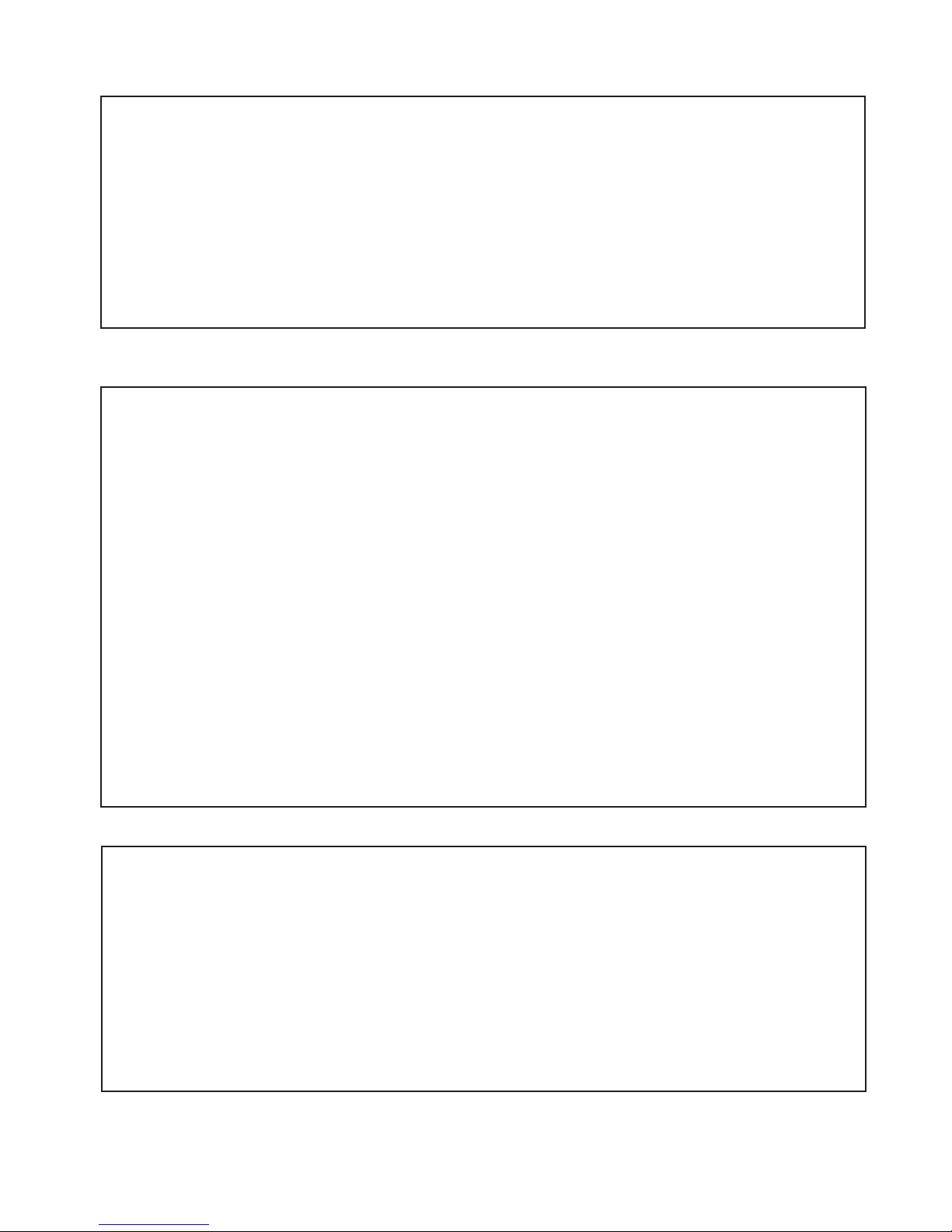
If a continuous unit centerline does not exist from the
original measuring process, it will be necessary to create one.
Lightly mark a continuous unit centerline on the threshold.
Next, mark a continuous unit centerline on each wall, starting
where the threshold centerline meets the wall. Use a level to
ensure the wall centerline is plumb and straight. The wall
centerlines should be a minimum of the unit height from the
threshold.
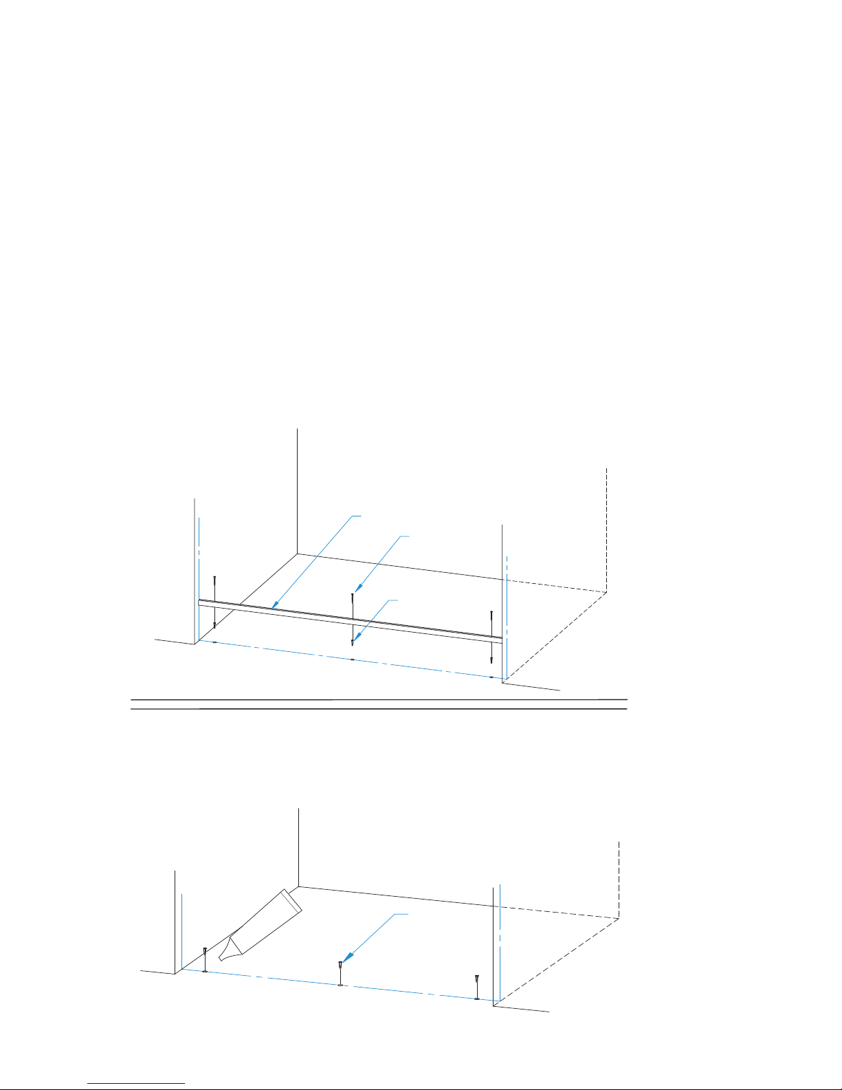
Note: Centerline (CL) is a term used to describe the center or
mid-point of the unit. The position of the unit centerline can
be located anywhere within the width of the threshold, as
long as adequate structure exists beneath the centerline for
fastening and the outer edges of the unit will not overhang
the threshold. The most common unit centerline position is
the middle of the threshold.
QCI0150 REV. 0 Page 5 of 14 Certified 06/04/10
2
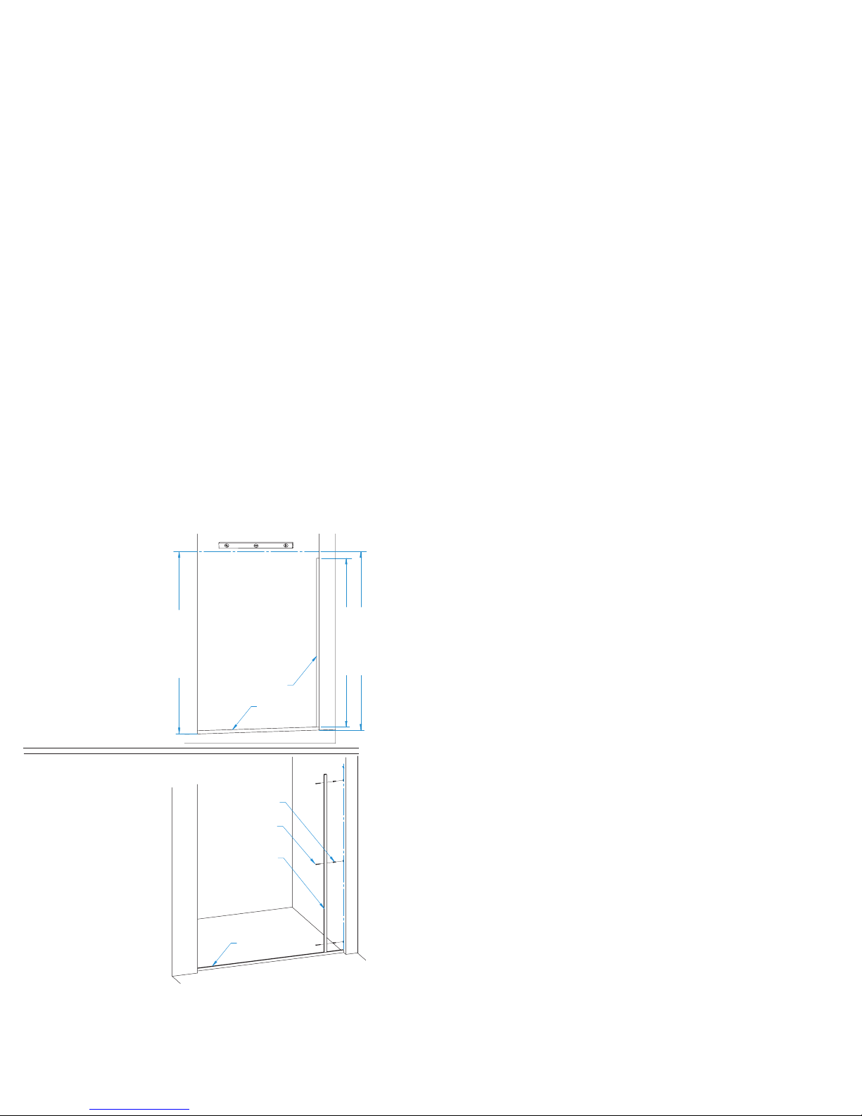
**IMPORTANT**
Keep both holes in-line to ensure
the header mounts level.
3/16"
Unit Height - 1/2”
Use a level to check the threshold for out of level conditions if the original
measured conditions are not available. If no conditions exist, measure up each wall
centerline a distance of Unit Height - 1/2” from the threshold, and clearly mark each location.
Note: Header Mount Hole = Unit Height - 1/2“ , or Panel Glass Height + 1 11/16”
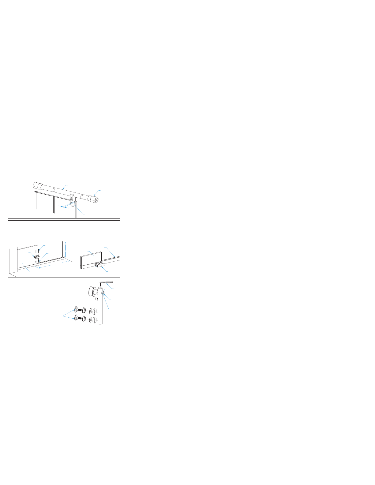
If out of level conditions exist; measure up the “high” side wall centerline a
distance of “Unit Height - 1/2” from the threshold and clearly mark this location.
For the wall centerline distance on the “low” side of the threshold, use a level to
determine the threshold out of level distance and add that value to the equation
“Unit Height - 1/2”. Measure this summed distance up the “low” side wall centerline,
from the threshold and clearly mark this location.
Next drill a 7/16” diameter hole approximately
3” deep, at each marked wall location.
(See illustration example.)
Unit Height - 1/2”
(Unit Height - 1/2”) + 3/16”
THRESHOLD OUT OF
LEVEL EXAMPLE. FOR
REFERENCE ONLY.