Rohde TE Series User manual

deutschenglish
françaisitalianoespañol
Bedienungsanleitung
Elektro-Toplader für Keramik bis 1320°C
Instruction Manual
Electric Toploaders for Ceramics up to 1320°C
Mode d'emploi
Fours électriques verticaux pour la céramique jusqu'à 1320°C
Istruzioni per l´uso
Forni elettrici a pozzetto per ceramica fino a 1320°C
Manual de instrucciones
Horno eléctrico de carga superior para cerámica hasta 1320°C

Seite 2von 16 Stand: 09/2017 Stand: 09/2017 Seite 3von 16
Aus Freude am Ergebnis
deutsch
1. VORWORT
Herzlichen Glückwunsch, Sie haben sich für einen ROHDE-Brennofen entschieden, einem Markenprodukt für höchste
Ansprüche. Dieser Toplader ist das Ergebnis intensiver Weiterentwicklung kleinerer und mittlerer Keramikbrennöfen.
Das Resultat ist ein 1320°C-Ofen* mit hochwertiger Innenauskleidung für Anwendungen in der Keramik- und Glas-
bearbeitung.
Diese Bedienungsanleitung soll Ihnen das Kennenlernen Ihres ROHDE-Topladers vereinfachen. Aus diesem Grund
haben wir einige wichtige Hinweise und Richtlinien zusammengefasst, um Ihnen einen einfachen und sicheren Umgang
mit Ihrem Brennofen zu ermöglichen. Bitte lesen Sie die Bedienungsanleitung vor der ersten Benutzung des ROHDE-
Toplader sorgfältig durch. Lernen Sie die Funktionsweisen Ihres Topladers und der Regelanlage kennen.
*ACHTUNG: Tmax. bei Ecotop 60 L abweichend.
2. PRODUKTFAMILIE
*ZWR = Zwischenring zur Erweiterung Sonderspannungen für alle EU-Netze auf Anfrage
INHALTSVERZEICHNIS Seite
1. Vorwort . . . . . . . . . . . . . . . . . . . . . . . . . . . . . . . . . . . . . . . . . . . . . . . . . . . . . . . . . . . . . . . . . . . . . . . . . . . 3
2. Produktfamilie. . . . . . . . . . . . . . . . . . . . . . . . . . . . . . . . . . . . . . . . . . . . . . . . . . . . . . . . . . . . . . . . . . . . . . 3
3. Übersicht . . . . . . . . . . . . . . . . . . . . . . . . . . . . . . . . . . . . . . . . . . . . . . . . . . . . . . . . . . . . . . . . . . . . . . . . . . 4
4. Wichtige Sicherheitshinweise. . . . . . . . . . . . . . . . . . . . . . . . . . . . . . . . . . . . . . . . . . . . . . . . . . . . . . . . . 5
4.1. Allgemeine Anmerkungen . . . . . . . . . . . . . . . . . . . . . . . . . . . . . . . . . . . . . . . . . . . . . . . . . . . . . . . . . . . . . . 5
4.2. Sicherheitshinweise . . . . . . . . . . . . . . . . . . . . . . . . . . . . . . . . . . . . . . . . . . . . . . . . . . . . . . . . . . . . . . . . . . . 5
4.3. Sicherheitshinweise für den Einsatz . . . . . . . . . . . . . . . . . . . . . . . . . . . . . . . . . . . . . . . . . . . . . . . . . . . . . . . 5
5. Inbetriebnahme. . . . . . . . . . . . . . . . . . . . . . . . . . . . . . . . . . . . . . . . . . . . . . . . . . . . . . . . . . . . . . . . . . . . . 6
5.1. Anlieferung/Ofen auspacken . . . . . . . . . . . . . . . . . . . . . . . . . . . . . . . . . . . . . . . . . . . . . . . . . . . . . . . . . . . 6
5.2. Verpackung entsorgen. . . . . . . . . . . . . . . . . . . . . . . . . . . . . . . . . . . . . . . . . . . . . . . . . . . . . . . . . . . . . . . . . 6
5.3. Betriebsumgebung/Aufstellort . . . . . . . . . . . . . . . . . . . . . . . . . . . . . . . . . . . . . . . . . . . . . . . . . . . . . . . . . . 6
5.4. Aufbau des Brennofens . . . . . . . . . . . . . . . . . . . . . . . . . . . . . . . . . . . . . . . . . . . . . . . . . . . . . . . . . . . . . . . . 6
5.5. Abluft installieren . . . . . . . . . . . . . . . . . . . . . . . . . . . . . . . . . . . . . . . . . . . . . . . . . . . . . . . . . . . . . . . . . . . . . 7
5.6. Zuluftschieber . . . . . . . . . . . . . . . . . . . . . . . . . . . . . . . . . . . . . . . . . . . . . . . . . . . . . . . . . . . . . . . . . . . . . . . 7
5.7. Netzanschluss/Regelanlage anschließen . . . . . . . . . . . . . . . . . . . . . . . . . . . . . . . . . . . . . . . . . . . . . . . . . . 7
5.8. Wandmontage der Regelanlage . . . . . . . . . . . . . . . . . . . . . . . . . . . . . . . . . . . . . . . . . . . . . . . . . . . . . . . . . . 8
5.9. Ofen einbrennen/Besatz einbrennen . . . . . . . . . . . . . . . . . . . . . . . . . . . . . . . . . . . . . . . . . . . . . . . . . . . . . 8
5.10. Hinweise Stromanschluss/RCD-Schutzschalter . . . . . . . . . . . . . . . . . . . . . . . . . . . . . . . . . . . . . . . . . . . . . 8
6. Allgemeine Bedienungshinweise . . . . . . . . . . . . . . . . . . . . . . . . . . . . . . . . . . . . . . . . . . . . . . . . . . . . . . 9
6.1. Bedienungshinweise Regelanlage . . . . . . . . . . . . . . . . . . . . . . . . . . . . . . . . . . . . . . . . . . . . . . . . . . . . . . . . 9
6.2. Richtiger Umgang beim Brand. . . . . . . . . . . . . . . . . . . . . . . . . . . . . . . . . . . . . . . . . . . . . . . . . . . . . . . . . . . 9
7. Weitere Funktionen . . . . . . . . . . . . . . . . . . . . . . . . . . . . . . . . . . . . . . . . . . . . . . . . . . . . . . . . . . . . . . . . 10
7.1. Transport/Verbringung . . . . . . . . . . . . . . . . . . . . . . . . . . . . . . . . . . . . . . . . . . . . . . . . . . . . . . . . . . . . . . . 10
7.1.1. Deckel abmontieren . . . . . . . . . . . . . . . . . . . . . . . . . . . . . . . . . . . . . . . . . . . . . . . . . . . . . . . . . . . . . . . . . . 10
7.1.2. Hauptring demontieren . . . . . . . . . . . . . . . . . . . . . . . . . . . . . . . . . . . . . . . . . . . . . . . . . . . . . . . . . . . . . . . 10
7.1.3. Zwischenring demontieren . . . . . . . . . . . . . . . . . . . . . . . . . . . . . . . . . . . . . . . . . . . . . . . . . . . . . . . . . . . . . 10
7.1.4. Fußgestell demontieren . . . . . . . . . . . . . . . . . . . . . . . . . . . . . . . . . . . . . . . . . . . . . . . . . . . . . . . . . . . . . . . 11
7.2. Wende-Fußgestell . . . . . . . . . . . . . . . . . . . . . . . . . . . . . . . . . . . . . . . . . . . . . . . . . . . . . . . . . . . . . . . . . . . 11
7.3. Besatzbeispiel . . . . . . . . . . . . . . . . . . . . . . . . . . . . . . . . . . . . . . . . . . . . . . . . . . . . . . . . . . . . . . . . . . . . . . 11
8. Wartung/Pflege/Reinigung . . . . . . . . . . . . . . . . . . . . . . . . . . . . . . . . . . . . . . . . . . . . . . . . . . . . . . . . 12
9. Tipps zur Störungssuche. . . . . . . . . . . . . . . . . . . . . . . . . . . . . . . . . . . . . . . . . . . . . . . . . . . . . . . . . . . . 12
10. Garantiebestimmungen. . . . . . . . . . . . . . . . . . . . . . . . . . . . . . . . . . . . . . . . . . . . . . . . . . . . . . . . . . . . . 13
11. Schutzrechte/Markennamen/Haftungsausschluss . . . . . . . . . . . . . . . . . . . . . . . . . . . . . . . . . . . . 13
12. Konformitätserklärung. . . . . . . . . . . . . . . . . . . . . . . . . . . . . . . . . . . . . . . . . . . . . . . . . . . . . . . . . . . . . . 14
13. Ersatzteile . . . . . . . . . . . . . . . . . . . . . . . . . . . . . . . . . . . . . . . . . . . . . . . . . . . . . . . . . . . . . . . . . . . . . . . . 15
14. Service-Adressen . . . . . . . . . . . . . . . . . . . . . . . . . . . . . . . . . . . . . . . . . . . . . . . . . . . . . . . . . . . . . . . . . . 15
Modell Tmax Innenmaße Außenmaße Leistung Strom Anschluss- Besatz- Gewicht
(mm) (mm) stecker platten Netto
Volumen °C b t h B T H kW A mm kg
Ecotop 20 1320 ø 330 230 560 560 520 2,3 10,0 Schuko ø 310 49
Ecotop 43 L 1320 ø 400 340 650 700 630 2,9 13,0 Schuko ø 350 72
Ecotop 50 1320 ø 400 380 650 700 725 3,6 16,0 Schuko ø 350 76
Ecotop 50 S 1320 ø 400 380 650 700 725 4,5 6,5 CEE16 A ø 350 76
Ecotop 60 L 1200 ø 400 450 650 700 740 2,9 13,0 Schuko ø 350 85
Ecotop 60 1320 ø 400 450 650 700 740 3,6 16,0 Schuko ø 350 85
Ecotop 60 S 1320 ø 400 450 650 700 740 5,0 10,0 CEE16A ø 350 85
Modell Tmax Innenmaße Außenmaße Leistung Strom Anschluss- Besatz- Gewicht
(mm) (mm) stecker platten Netto
Volumen °C b t h B T H kW A mm kg
TE 75 MCC+ 1320 ø470 460 720 740 800 6,0 13 CEE 16 ø420 101
ZWR75 MCC+ ø470 230 650 700 230 3,0 - - - 23
TE 110 MCC+ 1320 ø470 690 720 740 1030 9,0 13 CEE 16 ø420 123
TE100 MCC+ 1320 ø520 460 800 830 800 7,0 15 CEE 16 ø470 110
ZWR100 MCC+ ø520 230 800 830 230 3,5 - - - 22
TE150 MCC+ 1320 ø520 690 800 830 1030 10,5 15 CEE 16 ø470 130
TE130 MCC+ 1320 ø590 460 830 880 800 7,3 16 CEE 16 ø550 110
ZWR130 MCC+ ø590 230 830 880 230 3,7 - - - 25
TE190 MCC+ 1320 ø590 690 830 880 1030 11,0 16 CEE 16 ø550 150
TE200 MCC+ 1320 ø740 460 1000 1050 800 9,2 20 CEE 32 Zuschnitt 160
ZWR200 MCC+ ø740 230 1000 1050 230 4,6 - - - 32
TE300 MCC+ 1320 ø740 690 1000 1050 1030 13,8 20 CEE 32 Zuschnitt 190
Modell Tmax Innenmaße Außenmaße Leistung Strom Anschluss- Besatz- Gewicht
(mm) (mm) stecker platten Netto
Volumen °C b t h B T H kW A mm kg
TE 80 S 1320 ø 450 460 770 780 780 6,0 13 CEE 16 ø 420 115
ZWR 80 S ø 450 150 770 780 150 3,0 - - - 20
TE 100 S 1320 ø 450 610 770 780 930 9,0 13 CEE 16 ø 420 145
TE 95 S 1320 ø 520 460 850 800 775 7,0 16 CEE 16 ø 470 153
ZWR 95 S ø 520 230 850 800 230 3,5 - - - 35
TE 145 S 1320 ø 520 690 850 800 1000 10,5 16 CEE 16 ø 470 142
TE 130 S 1320 ø 610 460 950 950 770 8,8 19 CEE 32 ø 550 135
ZWR130 S ø 610 230 950 950 230 4,4 - - - 33
TE 200 S 1320 ø 610 690 950 950 1000 13,2 19 CEE 32 ø 550 190
TE 165 S 1320 730 630 460 1050 950 790 10,0 22 CEE 32 Zuschnitt 166
ZWR165 S 730 630 230 1050 950 230 5,0 - - - 36
TE 250 S 1320 730 630 690 1050 950 1020 15,0 22 CEE 32 Zuschnitt 222
TE 300 S 1320 830 630 690 1160 950 1020 15,0 22 CEE 32 Zuschnitt 225
Seite 4von 16 Stand: 09/2017 Stand: 09/2017 Seite 5von 16
Aus Freude am Ergebnis
deutsch
4. WICHTIGE SICHERHEITSHINWEISE
4.1. Allgemeine Anmerkung
Beachten Sie unbedingt die Sicherheitshinweise, aber auch die Sicherheitskennzeichen, um mögliche Gefährdungen
ausschließen zu können. Lesen Sie die folgenden Sicherheitshinweise in Ihrem eigenen Interesse vollständig durch,
bevor Sie den Brennofen in Betrieb nehmen.
Bewahren Sie die Bedienungsanleitung sorgfältig auf. Verwenden Sie zu Ihrer eigenen Sicherheit ausschließlich
ROHDE-Ersatzteile!
Die Helmut Rohde GmbH übernimmt keine Haftung für Schäden, welche durch falsche oder fehlerhafte Heizspiralen
eines Fremdherstellers entstehen. Ebenfalls erlöschen auch sämtliche Garantieansprüche mit dem Einbau nicht
originaler Ersatzteile!
4.2. Sicherheitshinweise
Achtung: Heiße Oberfläche,
nicht in heißem Zustand öffnen.
Achtung: Vor Öffnen des Elektro-
kastens Netzstecker ziehen! (BGV
A8).
Achtung: Warnung vor gefährlicher
elektrischer Spannung.
Das CE Zeichen bestätigt, dass das
Konformitätsbewertungs-Verfahren
nach EG-Richtlinien durchgeführt
wurde:
Richtlinie 2004 / 108 / EG
Richtlinie 93 / 68 EWG, CE-Kenn-
zeichnung.
4.3. Sicherheitshinweise für den Einsatz
Nur unter Einhaltung der folgenden Sicherheitshinweise kann ein gefahrloser Betrieb des ROHDE-Brennofens
ermöglicht werden:
• Bei Gewerbebetrieben sind der Brennofen und die Regelanlage vor der ersten Inbetriebnahme und im Zeitabstand
von 4Jahren durch eine Elektrofachkraft auf ordnungsgemäßen und einwandfreien Zustand nach BGV A3 Prüfung
zu prüfen.
• Reparatur und Wartungsarbeiten an elektrischen Bauteilen dürfen nur durch eine Elektrofachkraft durchgeführt
werden.
• Aus Sicherheitsgründen muss vor Wartungsarbeiten der Netzstecker gezogen werden.
• Es darf kein Verlängerungskabel verwendet werden!
Deckel mörtellos gefügt
Steine gegen Verrutschen
mechanisch verankert
Fase verhindert Befall
alle Modelle teilbar,
einige nachträglich erweiterbar
einzigartiges
Wende-Fußgestell
Zuluftschieber an allen
Topladermodellen
Wandaufbau Studio-Toplader
Serie TE-MCC+
Wandaufbau
Profi-Toplader
Serie TE-S
Wandaufbau
Ecotop-Toplader
Deckelverschluss,
justier- und abschließbar
Halbleiterrelais serienmäßig
in allen TE-S und Ecotop
Personenschutzschalter
Abluftstutzen
Metall-Transportgriffe
Heizspiralen passgenau fixiert
Thermoelement geschützt
eingebaut
Steinkanten sauber
bearbeitet
Deckel weit und leicht zu öffnen, stabile Aufstellungstabiles Deckel-Scharnier
gasdruckfederunterstützte
Deckelöffnung
114mm 110mm
95mm

Seite 6von 16 Stand: 09/2017 Stand: 09/2017 Seite 7von 16
Aus Freude am Ergebnis
deutsch
5.5. Abluft installieren
Achtung: Der Abluftstutzen wurde so konzipiert, dass
abstrahlende Hitze nicht an Wände, Flächen oder
Gegenstände strahlen kann. Wird der Abluftstutzen
am Brennofen montiert, kann das Abluftloch nicht ver-
schlossen werden. Möchten Sie das Abluftloch während
des Brandes verschließen, darf der Stutzen nicht ange-
schraubt werden.
Schrauben Sie den mitgelieferten Abluftstutzen (Bild 4)
an die dafür vorgesehene Bohrung auf der linken Seite
des Brennofens. Die Befestigungsstelle ist so gewählt,
dass austretende Dämpfe und Gase durch einen Abluft-
schlauch (optionales Zubehör) abgeleitet werden. Der
Abluftschlauch wird in den Abluftstutzen gesteckt (Bild
5) und mit der Fixierschraube im Stutzen befestigt.
5.6. Zuluftschieber
Alle Modelle der ROHDE-Toplader verfügen über einen Zuluftschieber (Bild 6) am Boden.
Ist der Zuluftschieber in linker Position, so ist die Luftzuführung unterbrochen. Wenn
der Schieber nach rechts zeigt, ist die Zuluft geöffnet.
Auch hier kann die Lebensdauer der Heizwendeln erheblich erhöht werden,
wenn die Zuluft bis ca. 600–700°C geöffnet ist.
5.7. Netzanschluss / Regelanlage anschließen
Der Ofen ist mit einem Anschlusskabel für Netzanschluss ausgestattet. Die entsprechenden Daten können dem
Typenschild entnommen werden. Die Stromzuführung muss dem Brennofen entsprechend ausgelegt und in unmittel-
barer Nähe des Brennofens sein. Verwenden Sie keinesfalls ein Verlängerungskabel! Das Zuleitungskabel
darf den heißen Ofen nicht berühren.
Spannungsschwankungen sind örtlich möglich. In
Deutschland kann die Nennspannung von 230/400 Volt
um 10% schwanken. Das führt zu einer Abweichung in
der Nennleistung. Fällt die Spannung unter Last auf
210Volt ab, so sinkt die Ofenleistung um ca.16%.
Die Regelanlage (Bild 7) wird über eine 14-polige Steck-
schraubverbindung an den Brennofen gekoppelt. Die
dafür vorgesehene schwarze Steckdose (Bild 8) am Ofen
befindet sich neben der elektrischen Zuleitung an der
Seite des Anschlusskastens.
Stecken Sie bitte zuerst den schwarzen Regelungsstecker
ein. Eventuell müssen Sie den Stecker etwas drehen, bis
er einrastet. Dann den Verschraubungsring festdrehen
und damit den Stecker sichern.
Bei allen erweiterbaren Brennöfen sind die für die Erwei-
terungen erforderlichen Anschlussmöglichkeiten (Bild 9)
bereits installiert (Bild 10).
Bild 4 Bild 5
Bild 7 Bild 8
Bild 9 Bild 10
Bild 6
5. INBETRIEBNAHME
5.1. Anlieferung / Ofen auspacken
Wird der ROHDE-Toplader auf Palette mit Spedition geliefert, prüfen Sie die Sendung sofort bei der Anlieferung auf
sichtbare Beschädigungen der Verpackung. Ist dies der Fall, packen Sie die Palette zusammen mit dem Fahrer aus
und prüfen die Ware erneut auf Beschädigungen. Vermerken Sie evtl. Schäden sofort auf dem Lieferschein und
lassen Sie den Fahrer unbedingt gegenzeichnen. Behalten Sie eine Kopie der Schadensreklamation. Melden Sie die
Beschädigung sofort der Transportfirma. Spätere Reklamationen sind zwecklos.
5.2. Verpackung entsorgen
Bringen Sie die Holz-, Karton- und Folienverpackung zu einer entsprechenden Entsorgungsstelle und helfen Sie mit,
aktiv den Umweltschutz zu fördern.
Weitere Informationen zum Entsorgen der Verpackungen erhalten Sie von Ihrem Händler oder der Gemeinde- bzw.
Stadtverwaltung.
5.3. Betriebsumgebung / Aufstellort
Wählen Sie einen geeigneten Aufstellort, beachten Sie dabei unbedingt folgende Regeln und bereiten Sie den Auf-
stellort entsprechend vor:
• Stellen Sie den Brennofen auf eine ebene Fläche.
• Der Abstand zu Wänden sollte an allen Seiten mindestens 25 cm betragen.
• Der Boden, Deckenisolierung, Wände, Trennwände, Verkleidungen etc. müssen aus schwer entflammbarem Material
sein.
• Achten Sie darauf, dass der Aufstellort gut belüftbar ist. Andernfalls muss eine Abluftanlage installiert werden.
Fragen Sie hierzu in jedem Fall einen Lüftungstechniker.
5.4. Aufbau des Brennofens
Kontrollieren Sie zunächst das
mitgelieferte Zubehör (Bild 1):
• 3 Cordierit-Klötzchen (6 Klötzchen bei TE 165/250 und TE 300)
• 1 Keramik-Rohr für Abluft
• 2 Verschlussstopfen
• 1 Kunststoffkappe für Fußgestell
• 1 Ersatz-Kunststoff-Fuß
• 1 Abluftstutzen inkl. Befestigungsschrauben
• 1 Montageplatte für Regelanlage inkl. Befestigungsschrauben
Die Regelanlage inkl. Bedienungsanleitung sowie die
Bedienungsanleitung zum Brennofen sind ebenfalls bei-
gelegt.
Montieren Sie zuerst die Montageplatte der Regelanlage
(Bild 2) an den dafür vorgesehenen Bohrungen am
Deckelbügel.
Nehmen Sie dann das Keramikrohr aus dem Karton und
stecken Sie es in das auf der linken Ofenseite vorhandene
Abluftloch (Bild 3).
Bild 2
Bild 1
Bild 3
Seite 8von 16 Stand: 09/2017 Stand: 09/2017 Seite 9von 16
Aus Freude am Ergebnis
deutsch
6. ALLGEMEINE BEDIENHINWEISE
6.1. Bedienung der Regelanlage
Bitte lesen Sie zunächst die entsprechende Betriebsanleitung für Ihre Regelanlage sorgfältig durch! Nach dem
Anschließen der Netzleitung sowie der Regelungszuleitung ist der Ofen betriebsbereit.
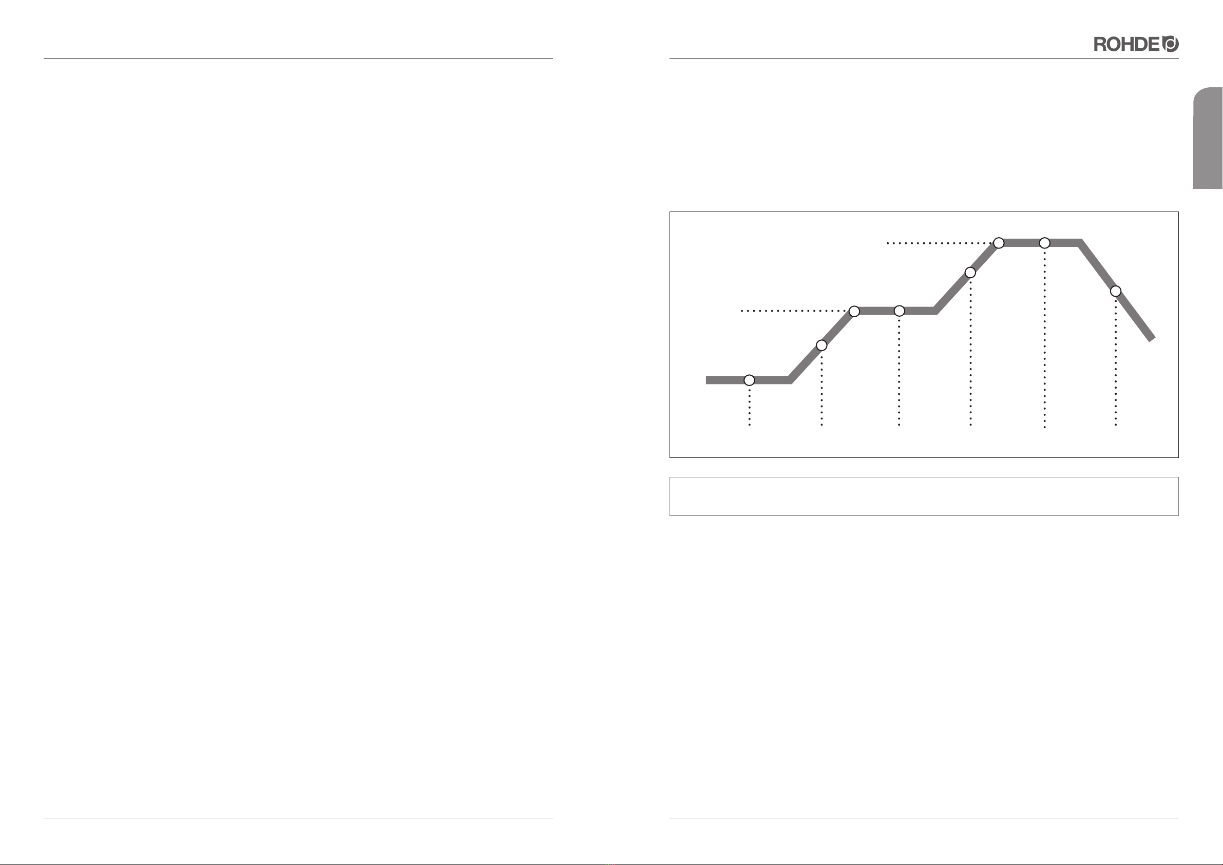
Typische Brennkurven am Beispiel einer Regelanlage TC 504
6.2. Richtiger Umgang beim Brand
• Keine brennbaren Gegenstände in unmittelbare Nähe legen.
• Der Brennofen darf nur in einem gut belüftbarem Raum aufgestellt und betrieben werden. Um einen zuverlässigen
Betrieb des Brennofens zu gewährleisten, darf der Ofen nur bis zu einer Umgebungstemperatur von 40°C betrieben
werden.
• Der Brennofen muss frei stehen. Die Wärmeabstrahlung darf nicht behindert werden. Legen Sie keine Gegenstände
auf oder am Ofen ab.
• Öffnen Sie keinesfalls den Brennofen, solange er noch in Betrieb oder nicht vollständig abgekühlt ist. Hohe, aus-
tretende Temperaturen führen zu Brand- und Verletzungsgefahr und führen zu vorzeitigem Verschleiß am Ofen.
Der Hersteller übernimmt dafür keinerlei Haftung.
• Brennen Sie Materialien, welche gesundheitsschädliche Gase und Dämpfe entwickeln, ist es unbedingt erforderlich,
eine Abluftanlage zu installieren und diese ins Freie umzuleiten.
• Brennen Sie niemals brennbare Materialien oder Lebensmittel im Ofen.
Schrühbrand0.00 100 600 0.10 150 950 0.05 SKIP
Glasurbrand 0.00 150 300 0.05 150 1050 0.20 SKIP
5.8. Wandmontage der Regelanlage
Montage der Regelanlage TC 304
Wählen Sie einen sicheren, gut bedienbaren Platz neben dem Ofen an der Wand. Schrauben Sie zuerst die beiden
mitgelieferten Rändelschrauben in die auf der Rückseite der Regelanlage vorgesehenen Löcher. Damit wird der Regler
später in der Halterung fixiert.
Montieren Sie jetzt mit Hilfe der 3 Dübel und 3 Schrauben die Befestigungsschiene der Regelanlage TC 304 so, dass
ein Befestigungsloch nach oben zeigt und zwei Löcher nach unten. Die Klarsichtschutzfolie muss in jedem Fall zu
Ihnen gerichtet sein!
Jetzt kann die Regelanlage von oben in die jeweilige Halterung eingehängt werden. U.U. müssen die Rändelschrauben
am Regler ein wenig gelockert werden.
Montage der anderen TC Modelle
Wählen Sie einen sicheren, gut bedienbaren Platz neben dem Ofen an der Wand. Die Wandhalterung der TC Regel-
anlagen abnehmen. Die Befestigungsteile mit 2 Dübeln und 2 Schrauben an der Wand befestigen. Jetzt kann die
Regelanlage von oben in die jeweilige Halterung gesteckt werden.
5.9. Ofen einbrennen / Besatzmaterial einbrennen
ACHTUNG: Entfernen Sie nun unbedingt die Schutzfolie vom gesamten Brennofen (Boden, Ringe und
Deckel)!!!
Bevor der Ofen in den täglichen Gebrauch geht, sollte ein Trockenbrand gefahren werden. Hierbei bitte das seitliche
Abluftloch und die Zuluft nicht verschließen. Das „Einbrennen“ ist zum einen nötig, um Restfeuchtigkeit aus der
Ofenwand zu entfernen, zum anderen wird durch dieses „Einbrennen“ eine schützende Oxydschicht auf den Heiz-
wendeln erzeugt, welche die Lebensdauer der Heizwendel entscheidend verlängert.
Leistungseinstellung für das Einbrennen:
• Aufheizen mit 100°C/h
• Endtemperatur 1050°C
• Haltezeit: 1 Std. 30 Min.
Beachten Sie bitte, dass das Offenlassen des Abluftlochs bis ca. 600–700°C, auch bei den zukünftigen Bränden,
die Lebensdauer der Heizwendeln erheblich erhöht.
Zeitgleich mit dem Einbrennen des Brennofens können Sie das Einbrennen der Hohlstützen und Besatzplatten (optio-
nales Zubehör) vornehmen. Weitere Informationen hierzu finden Sie unter Punkt 7.3.
Nach dem ersten Brand ist es dringend erforderlich, dass die Spannbänder am Deckel und Hauptring nachgezogen
werden. Weitere Informationen hierzu finden Sie unter Punkt 8.0.
5.10. Hinweise Stromanschluss / RCD-Schutzschalter
Für den Betrieb Ihres Brennofens in Werkstätten, Laborräumen, etc. ist es unbedingt erforderlich, eine separate
Stromzufuhr mit eigener Absicherung von einer Elektrofachkraft bereitstellen zu lassen.
RCD-Schutzschalter mit 0,03 A Auslösestrom (z.B. für Feuchträume in Wohnungen) können zum vorzeitigen Auslösen
(z.B. wegen Raumfeuchtigkeit bzw. Brenngutfeuchtigkeit) neigen.
Der RCD-Schutzschalter kann größer gewählt werden (Empfehlung 0,3A), wenn sichergestellt ist, dass der gewählte
Stromkreis ausschließlich nur für den Brennofen genutzt wird.
Falls dies nicht gewährleistet werden kann, ist ein Festanschluss vorzusehen.
tmp2
tmp1
t0 rmp1 t1 rmp2 t2 rmp3
Seite 10 von 16 Stand: 09/2017 Stand: 09/2017 Seite 11 von 16
Aus Freude am Ergebnis
deutsch
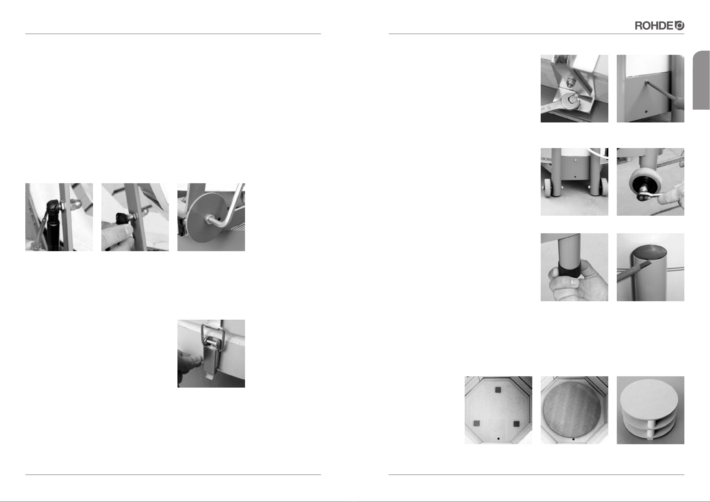
7.1.4. Fußgestell demontieren
Falls es noch erforderlich ist, kann auch das Fußgestell
vom Boden getrennt werden:
Hierzu muss die vordere (Bild 15) und hintere (Bild 16)
Befestigungsschraube gelöst werden. Sie können nun
den Boden abheben und ebenfalls waagrecht lagern.
Stellen Sie den Boden keinesfalls senkrecht auf den
Rand!
7.2. Wende-Fußgestell
Das Fußgestell wurde als „Wendegestell“ (Bild 17) konzi-
piert und kann auf eine optimale Arbeitshöhe eingestellt
werden:
Als erstes müssen die Transportrollen (nur bis TE 75
MCC+) abmontiert werden (Bild 18).
Danach lösen Sie die schwarzen Kunststoff-Füße und
entfernen diese vom Fußgestell (Bild 19).
Lösen Sie zuletzt die Kunststoffkappe (Bild 20) vom
oberen Teil des Fußgestells.
Wenden Sie nun das Fußgestell auf die richtige Arbeits-
höhe. Tauschen Sie nun die entsprechenden Bauteile auf
die gegenüberliegenden Befestigungsmöglichkeiten.
7.3. Besatzbeispiel
Platzieren Sie die 3 mitgelieferten Cordierit-Klötzchen (Bild 21) auf den Boden des Brennofens, dann legen Sie eine
erste Besatzplatte (optionales Zubehör) darauf (Bild 22). Beachten Sie, dass alle Besatzplatten und Stützen eingebrannt
werden müssen (siehe Punkt 5.9)! Eine zu nahe an die Heizwendeln gesetzte Platte ist stark rissgefährdet. Es sollten
mindestens 20 mm Abstand zur Spirale eingehalten werden.
Sehr zu empfehlen ist eine
3-Punkt-Auflage (Bild 23)
der Besatzplatten (bei
2-teiligen Besatzplatten
auch jeweils 3 Klötzchen
pro Platte), wobei jeweils
Stütze über Stütze stehen
sollte. Ansonsten werden
die Platten auf Biegung
beansprucht, was immer
wieder zu Verformungen
oder Rissen der Besatz-
platten führt.
Bild 20
Bild 17 Bild 18
Bild 19
Bild 21 Bild 22 Bild 23
Bild 15 Bild 16
7. WEITERE FUNKTIONEN
7.1. Transport/Verbringung
Für die Verbringung des Ofens an seinen endgültigen Aufstellort kann es notwendig werden, dass der Ofen zerlegt
werden muss, bei kleineren Modellen ist das meist nicht nötig. Ab TE 60 aufwärts ist es jedoch sehr hilfreich, den
Ofen in Deckel, Ringe und Boden zu zerlegen. Transportieren Sie den Ofen nur an den dafür vorgesehenen Trage-
griffen oder am Fußgestell.
Heben Sie den Brennofen nicht am Deckelbügel im Bereich des Sicherheitsschalters. Hier besteht die Gefahr, dass
der Sicherheitsschalter aus dem Rundloch gehebelt und die Funktion dadurch beeinträchtigt wird. Dies führt zum
Abschalten des Brennofens mit entsprechender Fehlermeldung.
7.1.1. Deckel abmontieren
Öffnen Sie den Deckel des Brennofens. Schieben Sie die Metallmanschette am Federkopf mit Hilfe eines Schrau-
benziehers so weit nach oben (Bild 11), bis Sie die Gasdruckfeder vom Kugelkopf (Bild 12) wegziehen können. Lassen
Sie den Deckel von einer Hilfskraft festhalten, damit dieser nicht auf den Hauptring fällt.
Als nächstes lösen Sie die beiden Innensechskantschrauben (Bild 13) mit einem Inbusschlüssel Größe 8 und ziehen
Sie beide Schrauben heraus. Nun können Sie den Deckel anheben und beiseitelegen. Legen Sie den abmontierten
Deckel flach auf eine ebene und glatte Fläche. Stellen Sie ihn keinesfalls senkrecht auf den Deckelrand!
Achten Sie darauf, dass der Sicherheitsschalter nach dem Zusammenbau des Topladers im Brennraum wieder
ordnungsgemäß in das Rundloch fällt. Ist dies nicht der Fall, kann es zum Abschalten des Brennofens mit entspre-
chender Fehlermeldung kommen.
7.1.2. Hauptring demontieren
Ab dem Brennofenmodell TE 60 ist der Hauptring vom
Boden teilbar. Für den Transport des Ofens ist der Spann-
verschluss mit einem Splint gesichert. Um den Hauptring
entfernen zu können, muss nun der Sicherungssplint
entfernt werden. Biegen Sie den Sicherungssplint (Bild 14)
in eine gerade, waagrechte Position und ziehen Sie diesen
aus dem Spannverschluss heraus.
7.1.3. Zwischenring demontieren
Hat Ihr Brennofen einen Zwischenring, so muss dieser für die Verbringung abmontiert werden. Stecken Sie den
Elektroanschluss vom Schaltkasten ab und gehen Sie wie in Punkt 7.1.2. beschrieben vor. Legen Sie Haupt- und
Zwischenring flach und ebenerdig ab, eine unsachgemäße Lagerung kann zu Beschädigungen der Feuerleichtsteine
führen! Stellen Sie ihn nicht senkrecht auf den Rand!
Bild 11
Bild 14
Bild 12 Bild 13
Seite 12 von 16 Stand: 09/2017 Stand: 09/2017 Seite 13 von 16
Aus Freude am Ergebnis
deutsch
Brennöfen und Maschinen für Keramik, Glas und Metall
Modell / Model:
Maximale Betriebstemperatur /
Maximum operating temperature:
SN:
16 A
1320 °C 50 Hz
7,3 kW
TE 95 S # 32694
3/N/PE AC 400 V
01 / 2013
Spannung /Voltage: Strom / Current: Leistung / Power:
Baujahr /Y. O. M.:
Helmut Rohde GmbH
Ried 9
D - 83134 Prutting
Frequenz:
CE
10. GARANTIEBESTIMMUNGEN
Wir garantieren einwandfreie Verarbeitung und Funktion des gelieferten Brennofens und gewähren 36 Monate Garantie
ab Rechnungsdatum.
Ausgenommen von der Garantie sind neben den Heizwendeln (Verschleißteile) folgende Punkte:
• Vom Kunden verursachte Beschädigungen, z.B. Steinabbrüche am Deckel, welche durch das Ablegen von
Gegenständen auf dem Deckel verursacht wurde.
• Beschädigungen, die vom Brenngut verursacht wurden, z.B. durch Überschreiten der maximalen Temperatur.
• Beschädigungen durch unsachgemäße(n) Transport(e).
• Beschädigungen durch nicht für den Ofen zulässige chemische Reaktionen während des Brandes (z. B.: Salzbrand).
• Korrosionsspuren, welche durch aggressive Glasuren bzw. unzureichende Belüftung des Brennraumes entstehen.
• Ausschluss jeglicher Haftung des Herstellers bei unsachgemäßem Umgang und damit entstandenen Schäden.
Wichtig: Die GARANTIEKARTE bitte sofort ausgefüllt zurücksenden! Beachten Sie bitte: Ohne die eingesandte
Garantiekarte ist eine kostenlose und schnelle Bearbeitung im Schadensfall nicht möglich.
Achtung: Die Feuerleichtsteine der Ausmauerung sind starken Temperaturschwankungen ausgesetzt. Dadurch
können Haarrisse in der Steinausmauerung entstehen. Dieser Vorgang ist normal und beeinträchtigt nicht die
Funktion des Ofens. Sie sind daher auch kein Anlass für eine Reklamation.
Was tun im Garantie-/Schadensfall?
Informieren Sie bitte Ihren Fachhändler – und zwar bevor etwaige Kosten entstehen. Ihr Fachhändler entscheidet
nach Rücksprache mit uns, dem Hersteller, was weiter zu tun ist.
Geben Sie bitte im Falle einer Reklamation den Ofen-Typ, die Produkt-Nr. und das Kaufdatum bzw. Baujahr an
(siehe Typenschild seitlich am Ofen).
Wir verweisen auf die Allgemeinen Geschäftsbedingungen (Stand: 18.12.2006) der Helmut Rohde GmbH.
11. SCHUTZRECHTE / MARKENNAMEN / HAFTUNGSAUSSCHLUSS
Der Inhalt dieser Bedienungsanleitung dient ausschließlich Informationszwecken, kann ohne Vorankündigung
geändert werden und ist nicht als Verpflichtung der Helmut Rohde GmbH anzusehen. Wir geben keine Garantie oder
Gewähr hinsichtlich der Richtigkeit oder Genauigkeit der Angaben in dieser Bedienungsanleitung.
Die Wiedergabe von Gebrauchsnamen, Handelsnamen, Warenbezeichnungen usw. in dieser Bedienungsanleitung
erfolgt ohne besondere Kennzeichnung, da diese allgemein bekannt sind. Diese Namen und Bezeichnungen können
jedoch Eigentum von Firmen oder Instituten sein.
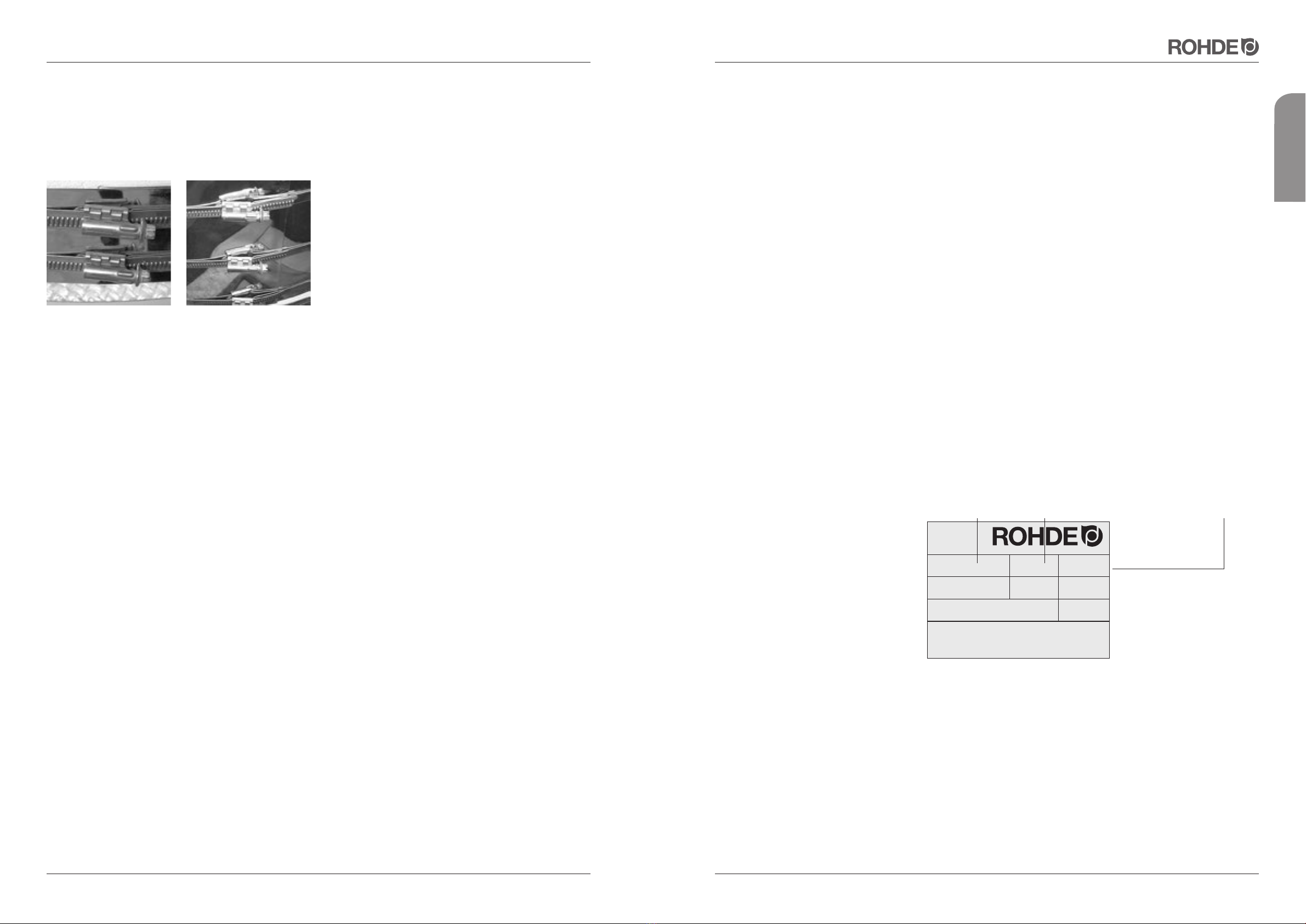
8. WARTUNG / PFLEGE / REINIGUNG
Da bei den ersten Bränden den Isoliersteinen die Restfeuchtigkeit entzogen wird, kann sich der Umfang des Brenn-
ofens minimal verändern. Deshalb ist es unbedingt erforderlich, dass nach den ersten Bränden die Spannbänder der
Edelstahlofenummantelung von Deckel (Bild 24) und Hauptring (Bild 25) leicht nachgespannt werden (nicht bei Quattro
und Brenntruhen).
Achten Sie darauf, dass keine Tone und Glasuren an die
Heizelemente gelangen. Dies führt unweigerlich bei den
nächsten Bränden zur Beschädigung der Heizwendel.
Sollten dennoch Verunreinigungen an den Heizleiter
gelangen, entfernen Sie diese sofort, da eingebrannte
Glasuren etc. die Heizwendel und die Steine beschä-
digen. Sprechen Sie bei größeren Schäden mit uns oder
Ihrem Fachhändler.
Heizwendeln sind Verschleißteile. Ihr Widerstand (Ohm) erhöht sich bei jedem Brand und führt im Laufe der Zeit zu
Verzögerungen der Brennkurve durch Leistungsabfall, vor allem im oberen Temperaturbereich. Wir empfehlen bei
fortgeschrittenem Verschleiß üblicherweise den Austausch der kompletten Heizwendeln, da einzeln ausgetauschte
Heizwendeln zu Temperaturdifferenzen innerhalb des Ofens führen können.
Lassen Sie die Heizwendel durch eine Elektrofachkraft tauschen!
Ein Tipp für den Brenn-Profi: Legen Sie sich einen kompletten Satz Heizwendeln auf Reserve!
Dies verhindert unnötigen Stress im Notfall und sichert Ihnen unverzügliche Brennfortsetzung.
Reinigen Sie den Brennofen regelmäßig von Ton- bzw. Steinstaub mittels Besen und Staubsauger. So verlängern Sie
auch die Lebensdauer Ihrer Heizwendel.
Vermeiden Sie nach Möglichkeit reduzierende Glasurbrände, da diese zum Abbau der Oxydationsschicht führen und
somit die Lebensdauer der Heizwendel erheblich verkürzen.
Es ist ratsam ca. alle 20 Brände einen Leerbrand (ohne Besatz) durchzuführen. Dabei werden die Heizwendel
„gesäubert“, gleichzeitig kann sich die Oxydschicht erneuern und verhelfen den Wendeln zu längerer Lebensdauer!
9. TIPPS ZUR STÖRUNGSSUCHE
Die Regelanlage kann nicht eingeschalten werden.
• Überprüfen Sie, ob die Regelanlage am Schaltkasten des Ofens eingesteckt wurde.
• Prüfen Sie weiterhin, ob der Brennofen am Stromanschluß angeschlossen ist.
• Überprüfen Sie die Feinsicherung am Stromkasten des Brennofens. Diese ist mit T 2A abgesichert.
• Lassen Sie Ihre Hausanschlüsse (Stecker), Sicherungen und die Stromaufnahme des Brennofens durch eine Elektro-
fachkraft prüfen.
Die Regelanlage zeigt eine Fehlermeldung.
Hierzu können Sie in der Bedienungsanleitung für die Regelanlage die entsprechende Vorgehensweise finden.
Der Brennraum erwärmt sich nicht. Überprüfen Sie die Funktion des Deckelschalters. Vermutlich arbeitet der
Deckelschalter nicht und somit kann der Sicherheitsschütz nicht schalten. Achten Sie darauf, dass der Sicherheits-
schalter ordnungsgemäß in das Rundloch fällt. Ist dies nicht der Fall, ist der Sicherheitskreis unterbrochen und der
Brennofen kann nicht heizen.
Der Brennofen heizt nur sehr langsam. Die eingegebenen Temperaturen werden nicht erreicht. Die Regelanlage
zeigt eine Fehlermeldung. Überprüfen Sie die Heizleiter auf evtl. sichtbaren Bruch.
Alle ROHDE-Brennöfen wurden vor Verlassen der Produktionsstätte eingeschalten und auf Funktion
geprüft!
Bild 24 Bild 25
Seite 14 von 16 Stand: 09/2017 Stand: 09/2017 Seite 15 von 16
Aus Freude am Ergebnis
deutsch
Directive 2006/95/EC
Electrical Apparatus Low Voltage Directive
The Manufacturer Die Firma La empresa
certifies and declares under its sole Erklärt in alleiniger Declara bajo su exclusiva
responsibility that the following Verantwortung, daß folgendes responsabilidad que el siguiente
product: Produkt: producto:
TE Toplader
to which this Declaration of Conformity relates, auf das sich diese Erklärung bezieht, mit al que se refiere la presente declaración está
is in conformity with the following directives and standards: folgenden Richtlinien bzw.Normen conforme con las siguientes directivas y normas:
• Electromagnetic compatibility directive übereinstimmt: • Directiva 2004/108/CE, Compatibilidad
(EMC) (2004/108/EEC) • Richtlinie 2004/108/EG, Elektromag. electromagnética
• Directive 93/68/ECC relating to CE marking Verträglichkeit • Directiva 93/68/ CEE, Denominación CE
• Richtlinie 93/68/ EWG, CE Kennzeichnung
European Standard - Europäische Normen - Normas europeas
EN 60204-1 ed. 2 EN 60439-1 ed. 2 EN 61000-6-4 ed. 2
EN 55011 ed. 2 EN ISO 13732-1 ISO 11684
ISO 7000 EN 60519-1 ed. 2 EN 60519-2 ed. 2
Documentation evidencing Die oben genannte Firma hält La empresa mencionada anteriormente
conformity with the requirements of Dokumentationen als Nachweis der tiene a disposición para inspección los
the Directives is kept available for Erfüllung der Sicherheitsziele und die documentos que confirman el
inspection at the above wesentlichen Schutzanforderungen cumplimiento de los objetivos de
mentioned Manufacturer. zur Einsicht bereit. seguridad y los requisitos de protección
esenciales.
11.04.12
Benjamin Rohde
Managing director - Geschäftsführer - Direttore amministrativo
CZECH REPUBLIC
ROHDE, spol. s.r.o.
67126 Dyjákovice, Dyjákovice 311
EC DECLARATION OF CONFORMITY
EU-KONFORMITÄTSERKLÄRUNG
DECLARACIÓN DE CONFORMIDAD UE
CE
12. KONFORMITÄTSERKLÄRUNG 13. ERSATZTEILE
Halten Sie bei Ersatzteilbestellungen immer Ihre Kaufrechnung griffbereit.
Diese beinhaltet alle ofenrelevanten Daten, welche für eine rasche und genaue Ersatzteilbestellung erforderlich sind.
14. SERVICE-ADRESSEN
Bei Fragen zu Ihrem Brennofen, Ersatzteilen oder weiterem Zubehör wenden Sie sich bitte an Ihren Fachhändler.
Wir wünschen Ihnen viel Erfolg und immer gute Brennergebnisse!
Ihr ROHDE-Team
Helmut Rohde GmbH · Ried 9· D-83134 Prutting
info@rohde-online.net · www.rohde-online.net

english
Seite 16 von 16 Stand: 09/2017
Aus Freude am Ergebnis
Instruction Manual
Electric Toploaders for Ceramics up to 1320°C

Page 2of 16 Level: 02/2013 Level: 02/2013 Page 3of 16
Enjoy your results
english
1. PREFACE
Congratulations, you have chosen a ROHDE product - a high-quality product meeting highest requirements. This
Toploader has resulted from intense research in the field of small to medium-sized ceramic kilns. We are pleased to
offer you a kiln fitted with high-quality lining, suitable for different types of ceramic and glass applications.
This instruction manual will help you to familiarise yourself with your new kiln. We have put together some important
information and guidelines that will make operating your kiln as safe and simple as possible. Please read the instruc-
tion manual carefully before using your kiln for the first time. Make sure you understand the features and functions of
the kiln and control unit.
*PLEASE NOTE: Different Tmax for Ecotop 60 L.
2. PRODUCT FAMILY
*ZWR = Supplementary ring for extension Special voltage electric supply for all EU networks available on request
CONTENTS Page
1. Preface . . . . . . . . . . . . . . . . . . . . . . . . . . . . . . . . . . . . . . . . . . . . . . . . . . . . . . . . . . . . . . . . . . . . . . . . . . 19
2. Product family . . . . . . . . . . . . . . . . . . . . . . . . . . . . . . . . . . . . . . . . . . . . . . . . . . . . . . . . . . . . . . . . . . . . 19
3. Overview . . . . . . . . . . . . . . . . . . . . . . . . . . . . . . . . . . . . . . . . . . . . . . . . . . . . . . . . . . . . . . . . . . . . . . . . . 20
4. Important safety instructions . . . . . . . . . . . . . . . . . . . . . . . . . . . . . . . . . . . . . . . . . . . . . . . . . . . . . . . . 21
4.1. General information . . . . . . . . . . . . . . . . . . . . . . . . . . . . . . . . . . . . . . . . . . . . . . . . . . . . . . . . . . . . . . . . . . 21
4.2. General safety instructions . . . . . . . . . . . . . . . . . . . . . . . . . . . . . . . . . . . . . . . . . . . . . . . . . . . . . . . . . . . . 21
4.3. Operating safety instructions . . . . . . . . . . . . . . . . . . . . . . . . . . . . . . . . . . . . . . . . . . . . . . . . . . . . . . . . . . 21
5. Start-up . . . . . . . . . . . . . . . . . . . . . . . . . . . . . . . . . . . . . . . . . . . . . . . . . . . . . . . . . . . . . . . . . . . . . . . . . . 22
5.1. Delivery / Unpacking the kiln . . . . . . . . . . . . . . . . . . . . . . . . . . . . . . . . . . . . . . . . . . . . . . . . . . . . . . . . . . . 22
5.2. Disposal of packing material . . . . . . . . . . . . . . . . . . . . . . . . . . . . . . . . . . . . . . . . . . . . . . . . . . . . . . . . . . . 22
5.3. Installation environment / Location . . . . . . . . . . . . . . . . . . . . . . . . . . . . . . . . . . . . . . . . . . . . . . . . . . . . . . 22
5.4. Assembly of kiln . . . . . . . . . . . . . . . . . . . . . . . . . . . . . . . . . . . . . . . . . . . . . . . . . . . . . . . . . . . . . . . . . . . . 22
5.5. Installation of ventilation system . . . . . . . . . . . . . . . . . . . . . . . . . . . . . . . . . . . . . . . . . . . . . . . . . . . . . . . . . 23
5.6. Air supply handle . . . . . . . . . . . . . . . . . . . . . . . . . . . . . . . . . . . . . . . . . . . . . . . . . . . . . . . . . . . . . . . . . . . . 23
5.7. Connecting to power supply / controller . . . . . . . . . . . . . . . . . . . . . . . . . . . . . . . . . . . . . . . . . . . . . . . . . . 23
5.8. Mounting the controller on the wall . . . . . . . . . . . . . . . . . . . . . . . . . . . . . . . . . . . . . . . . . . . . . . . . . . . . . . 24
5.9. Kiln and furniture initial firing . . . . . . . . . . . . . . . . . . . . . . . . . . . . . . . . . . . . . . . . . . . . . . . . . . . . . . . . . . . 24
5.10. Instructions power connection / Residual current protective device (RCD) . . . . . . . . . . . . . . . . . . . . . . . . 24
6. General operating instructions . . . . . . . . . . . . . . . . . . . . . . . . . . . . . . . . . . . . . . . . . . . . . . . . . . . . . . 25
6.1. Operating instructions Controller . . . . . . . . . . . . . . . . . . . . . . . . . . . . . . . . . . . . . . . . . . . . . . . . . . . . . . . 25
6.2. Correct operation during firing . . . . . . . . . . . . . . . . . . . . . . . . . . . . . . . . . . . . . . . . . . . . . . . . . . . . . . . . . 25
7. Other features . . . . . . . . . . . . . . . . . . . . . . . . . . . . . . . . . . . . . . . . . . . . . . . . . . . . . . . . . . . . . . . . . . . . 26
7.1. Transport / Delivery . . . . . . . . . . . . . . . . . . . . . . . . . . . . . . . . . . . . . . . . . . . . . . . . . . . . . . . . . . . . . . . . . . 26
7.1.1. Dismounting kiln cover . . . . . . . . . . . . . . . . . . . . . . . . . . . . . . . . . . . . . . . . . . . . . . . . . . . . . . . . . . . . . . . 26
7.1.2. Dismounting kiln main ring . . . . . . . . . . . . . . . . . . . . . . . . . . . . . . . . . . . . . . . . . . . . . . . . . . . . . . . . . . . . 26
7.1.3. Dismounting supplementary ring . . . . . . . . . . . . . . . . . . . . . . . . . . . . . . . . . . . . . . . . . . . . . . . . . . . . . . . . 26
7.1.4. Dismounting kiln stand . . . . . . . . . . . . . . . . . . . . . . . . . . . . . . . . . . . . . . . . . . . . . . . . . . . . . . . . . . . . . . . 27
7.2. Swivel kiln stand . . . . . . . . . . . . . . . . . . . . . . . . . . . . . . . . . . . . . . . . . . . . . . . . . . . . . . . . . . . . . . . . . . . . 27
7.3. Example for positioning furniture plates . . . . . . . . . . . . . . . . . . . . . . . . . . . . . . . . . . . . . . . . . . . . . . . . . . . 27
8. Maintenance / Care and Cleaning . . . . . . . . . . . . . . . . . . . . . . . . . . . . . . . . . . . . . . . . . . . . . . . . . . . . 28
9. Troubleshooting tips . . . . . . . . . . . . . . . . . . . . . . . . . . . . . . . . . . . . . . . . . . . . . . . . . . . . . . . . . . . . . . . 28
10. Warranty . . . . . . . . . . . . . . . . . . . . . . . . . . . . . . . . . . . . . . . . . . . . . . . . . . . . . . . . . . . . . . . . . . . . . . . . . 29
11. Property rights / Trade names and Disclaimer . . . . . . . . . . . . . . . . . . . . . . . . . . . . . . . . . . . . . . . . . 29
12. Declaration of Conformity . . . . . . . . . . . . . . . . . . . . . . . . . . . . . . . . . . . . . . . . . . . . . . . . . . . . . . . . . . 30
13. Spare parts . . . . . . . . . . . . . . . . . . . . . . . . . . . . . . . . . . . . . . . . . . . . . . . . . . . . . . . . . . . . . . . . . . . . . . . 31
14. Contacts / Assistance . . . . . . . . . . . . . . . . . . . . . . . . . . . . . . . . . . . . . . . . . . . . . . . . . . . . . . . . . . . . . . 31
Model Tmax Internal dimens. External dimens. Power Power Connection Furniture Weight
(mm) (mm) consumption plug plates Net
Volume °C w d h W D H kW A mm kg
Ecotop 20 1320 ø 330 230 560 560 520 2.3 10.0 Schuko ø 310 49
Ecotop 43 L 1320 ø 400 340 650 700 630 2.9 13.0 Schuko ø 350 72
Ecotop 50 1320 ø 400 380 650 700 725 3.6 16.0 Schuko ø 350 76
Ecotop 50 S 1320 ø 400 380 650 700 725 4.5 6.5 CEE 16 A ø 350 76
Ecotop 60 L 1200 ø 400 450 650 700 740 2.9 13.0 Schuko ø 350 85
Ecotop 60 1320 ø 400 450 650 700 740 3.6 16.0 Schuko ø 350 85
Ecotop 60 S 1320 ø 400 450 650 700 740 5.0 10.0 CEE16A ø 350 85
Model Tmax Internal dimens. External dimens. Power Power Connection Furniture Weight
(mm) (mm) consumption plug plates Net
Volume °C w d h W D H kW A mm kg
TE 75 MCC+ 1320 ø470 460 720 740 800 6.0 13 CEE 16 ø420 101
ZWR75 MCC+ ø470 230 650 700 230 3.0 - - - 23
TE 110 MCC+ 1320 ø470 690 720 740 1030 9.0 13 CEE 16 ø420 123
TE100 MCC+ 1320 ø520 460 800 830 800 7.0 15 CEE 16 ø470 110
ZWR100 MCC+ ø520 230 800 830 230 3.5 - - - 22
TE150 MCC+ 1320 ø520 690 800 830 1030 10.5 15 CEE 16 ø470 130
TE130 MCC+ 1320 ø590 460 830 880 800 7.3 16 CEE 16 ø550 110
ZWR130 MCC+ ø590 230 830 880 230 3.7 - - - 25
TE190 MCC+ 1320 ø590 690 830 880 1030 11.0 16 CEE 16 ø550 150
TE200 MCC+ 1320 ø740 460 1000 1050 800 9.2 20 CEE 32 cut-to-size 160
ZWR200 MCC+ ø740 230 1000 1050 230 4.6 - - - 32
TE300 MCC+ 1320 ø740 690 1000 1050 1030 13.8 20 CEE 32 cut-to-size 190
Model Tmax Internal dimens. External dimens. Power Power Connection Furniture Weight
(mm) (mm) consumption plug plates Net
Volume °C w d h W D H kW A mm kg
TE 80 S 1320 ø 450 460 770 780 780 6.0 13 CEE 16 ø 420 115
ZWR 80 S ø 450 150 770 780 150 3.0 - - - 20
TE 100 S 1320 ø 450 610 770 780 930 9.0 13 CEE 16 ø 420 145
TE 95 S 1320 ø 520 460 850 800 775 7.0 16 CEE 16 ø 470 153
ZWR 95 S ø 520 230 850 800 230 3.5 - - - 35
TE 145 S 1320 ø 520 690 850 800 1000 10.5 16 CEE 16 ø 470 142
TE 130 S 1320 ø 610 460 950 950 770 8.8 19 CEE 32 ø 550 135
ZWR130 S ø 610 230 950 950 230 4.4 - - - 33
TE 200 S 1320 ø 610 690 950 950 1000 13.2 19 CEE 32 ø 550 190
TE 165 S 1320 730 630 460 1050 950 790 10.0 22 CEE 32 cut-to-size 166
ZWR165 S 730 630 230 1050 950 230 5.0 - - - 36
TE 250 S 1320 730 630 690 1050 950 1020 15.0 22 CEE 32 cut-to-size 222
TE 300 S 1320 830 630 690 1160 950 1020 15.0 22 CEE 32 cut-to-size 225
Page 4of 16 Level: 02/2013 Level: 02/2013 Page 5of 16
Enjoy your results
english
4. IMPORTANT SAFETY INSTRUCTIONS
4.1. General information
Please make sure that you fully understand both the safety instructions and the safety icons, in order to eliminate
potential dangers. Before starting to operate the kiln, make sure that you read and fully understand the following
safety instructions.
Keep your instruction manual available at all times. For your own safety only use original spare parts!
Helmut Rohde GmbH does not assume any liability for damage resulting from incorrect or defective heating elements
from other manufacturers. Use only original spare parts - otherwise all warranty claims become void.
4.2. General safety instructions
4.3. Operating safety instructions
The ROHDE kiln can only be operated safely if the safety instructions are carefully followed:
• When operated industrially, the kiln and controller must undergo a safety check to ensure correct functionality. This
should be carried out by a qualified electrician before the initial operation and then at 4-year intervals in accordance
with BGV A3.
• Maintenance and repair of electronic components must be carried out by a qualified electrician.
• For safety reasons the kiln must be disconnected from the mains supply before any maintenance work is carried
out.
• The kiln must not be operated with an extension cable!
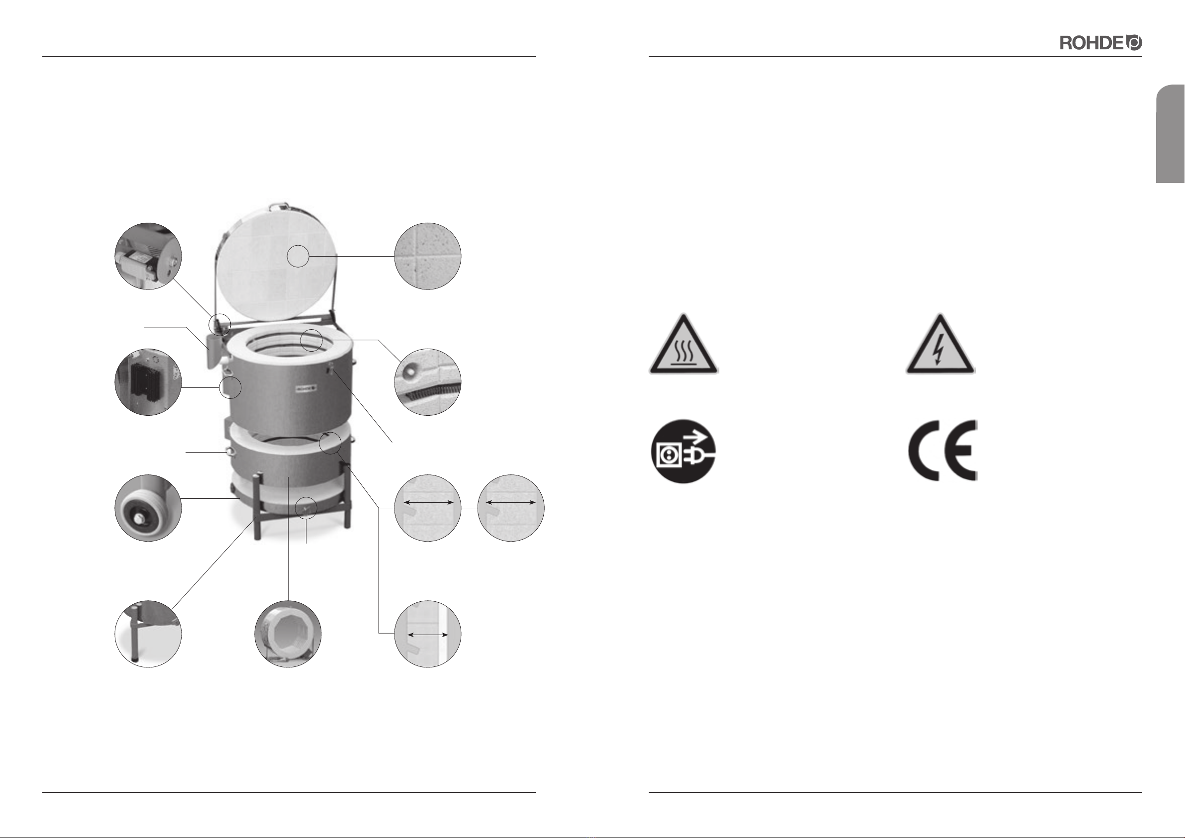
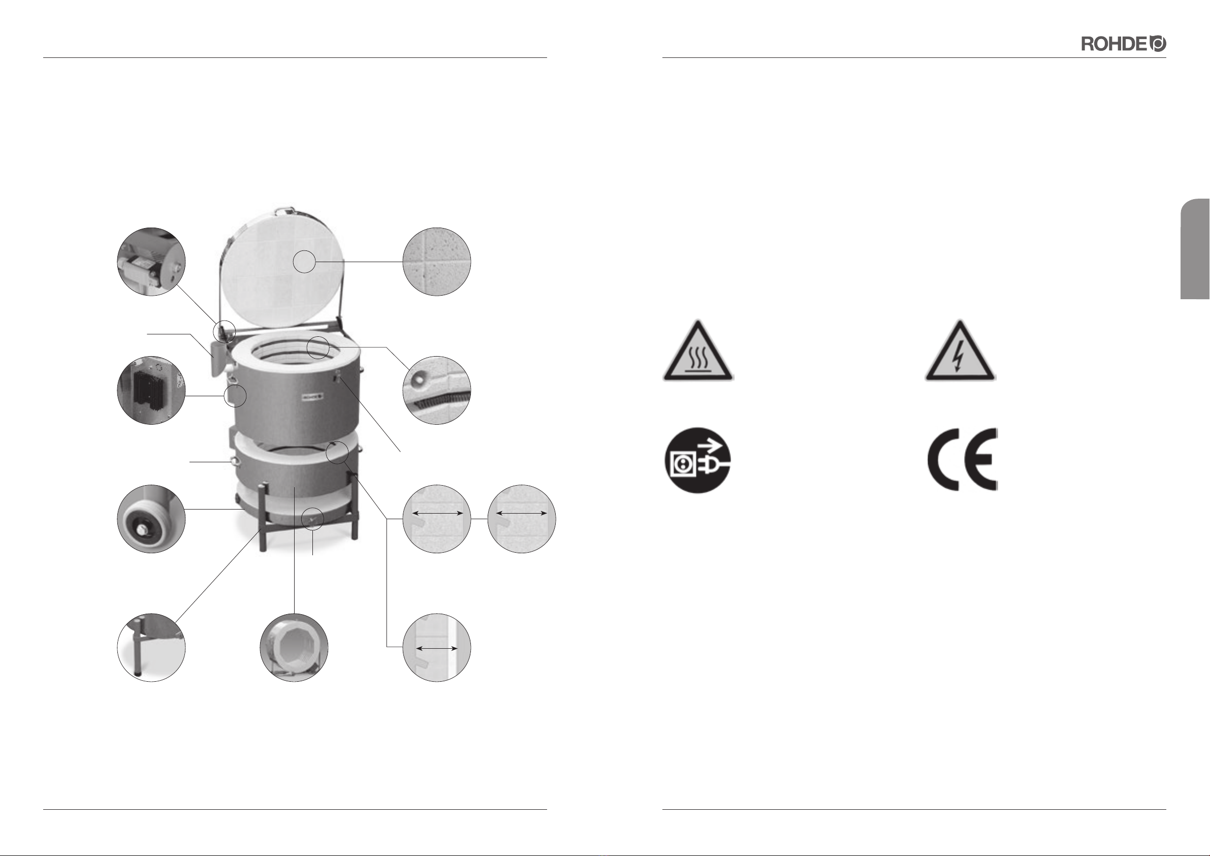
3. OVERVIEW
Kiln cover joined mortar-free
Bricks are secured against
displacement
All models can be disassem-
bled, some can be extended
Unique swivel kiln stand
Castors on back legs for
easy transport (TE 20–110)
Air supply handle for all
Toploader models
Wall structure Toploader
studio series TE-MCC+
Wall structure
Toploader
professional series
TE-S
3-layer wall
structure Ecotop
Adjustable and lockable
cover sealing
Solid State Relays standard
for all TE-S and Ecotop models
Safety switch
Exhaust air socket
Metal handles for
transport
Heating elements fixed in exact position
Thermocouple installed in a safe
position
Tidy brick edges
Cover can be opened easily to its widest
angle, stable frame
Pressure spring-supported
opening mechanism on
cover
114mm 110mm
95mm
Caution: Hot surface.
Do not open while hot.
Caution: Disconnect power plug
before opening the switch box!
(BGV A8).
Caution: Dangerous electrically live
components.
The CE marking indicates that the
inspections for conformity have
been correctly carried out in accor-
dance with EC standards:
Directive 2004/108/EC
Directive 93/68/ECC relating to CE
marking.
Page 6of 16 Level: 02/2013 Level: 02/2013 Page 7of 16
Enjoy your results
english
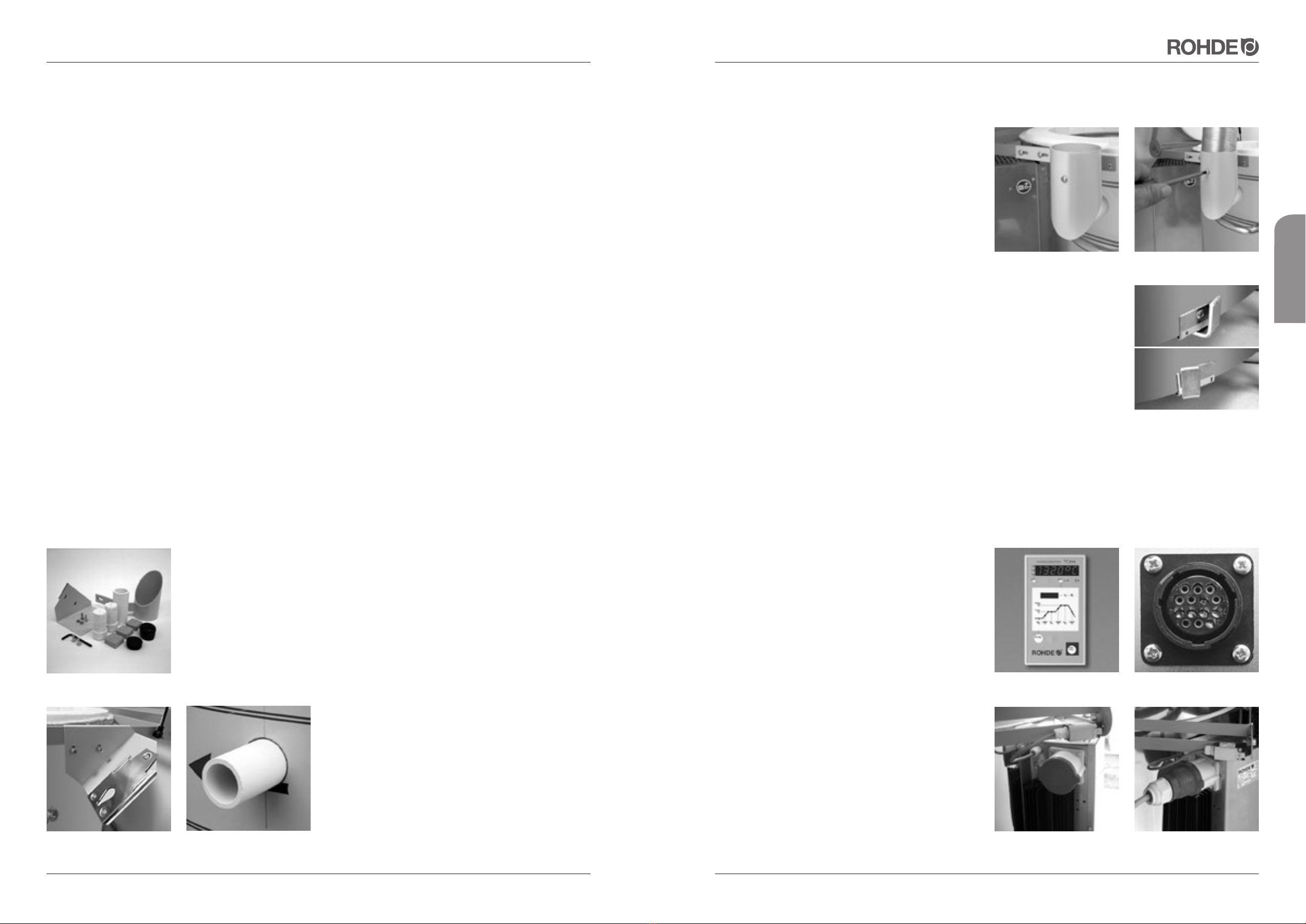
5.5. Installation of ventilation system
Please note: The exhaust socket has been designed to
prevent heat from radiating against walls, surfaces or
other objects. If the exhaust socket is mounted onto the
kiln, the exhaust opening cannot be closed. Do not attach
the socket if you wish to close the exhaust opening during
firing. Screw the exhaust air socket (figure 4) into the ho-
le on the left side of the kiln. The opening has been loca-
ted in a position that will allow fumes and gases to be
released through an exhaust air socket (optional
accessory). Plug the exhaust air tube into the exhaust air
socket (figure 5) and use the fixing screw to fix it to the
socket.
5.6. Air supply handle
All ROHDE Toploader models are equipped with an air supply handle (figure 6) on the
kiln base. When the handle points to the left, the air supply is cut off. When the handle
points to the right, the air supply is open.
You can significantly increase the service life of the heating elements by
opening the air supply up to a temperature of 600 – 700°C.
5.7. Connecting to power supply / controller
The kiln is equipped with a mains supply cable. The power supply data can be seen on the type plate. The power
supply must be suitable for the requirements of the kiln. The plug must be located next to the kiln.
Do not use extension cables! The mains supply cable must not come into contact with the hot kiln!
Regional voltage fluctuations are possible and will lead to
fluctuations in the nominal output. In Germany, for
instance, the nominal voltage of 230/400 is subject to
voltage fluctuations of 10%. If the voltage drops from 230
to 210 under load, the output of the kiln will be reduced
by 16%.
The controller (figure 7) is connected to the kiln with a
14-pin plug-and-screw connection. You will find the black
socket (figure 8) next to the electric connection on the
side of the switch cabinet.
First plug in the black plug of the controller. You might
need to turn it a little until it locks into position. Then turn
the screw connection ring, in order to protect the con-
nection.
All connections required for extension (figure 9) of exten-
dable Toploader kilns are already installed (figure 10).
figure 4 figure 5
figure 7 figure 8
figure 9 figure 10
figure 6
5. START-UP
5.1. Delivery / Unpacking of kiln
The ROHDE Toploader will usually be delivered on a pallet by a freight-forwarding agent. Immediately after delivery
check the packaging for any visible damage. Should you detect any damage, unpack the pallet together with the
driver and check the goods again for damage. If you detect any damage please enter details on the delivery note
and let the driver countersign your remarks. Keep one copy of the complaint for yourself. Inform the freight-forwarding
agency immediately of the damage. Complaints submitted at a later date cannot be taken into consideration.
5.2. Disposal of packing material
Contribute to a clean environment by disposing of wood, cardboard and plastic packaging material in your nearest
waste disposal plant. For further information concerning the disposal of packaging material please contact your
dealer or community council.
5.3. Installation environment / Location
When selecting a suitable place for your kiln, please note the following guidelines and prepare the kiln environment
accordingly:
• Place the kiln on an even surface.
• The distance to the walls should be at least 25 cm on each side.
• The floor, ceiling insulation, walls, dividing walls, panelling, etc. must be made of flame resistant material.
• Make sure that the kiln environment can be properly ventilated. Otherwise a ventilation system must be installed.
Please consult a qualified ventilation specialist to find out whether a ventilation system is necessary.
5.4. Assembly of kiln
Check the enclosed accessories first (figure 1):
• 3 cordierite blocks (6 blocks for TE 165/250 and TE 300)
• 1 ceramic tube for exhaust air
• 2 sealing plugs
• 1 plastic cap for kiln stand
• 1 spare part for kiln stand
• 1 exhaust air socket and fixing screws
• 1 panel for mounting the controller and fixing screws
You will also find enclosed the controller as well as two
instruction manuals for the controller and the kiln. First
screw the mounting panel (figure 2) into the holes indica-
ted on the cover bolt. Take the ceramic tube out of the
box and plug it onto the exhaust air opening on the left
side of the kiln (figure 3).
figure 2
figure 1
figure 3

Page 8of 16 Level: 02/2013 Level: 02/2013 Page 9of 16
Enjoy your results
english
6. GENERAL SAFETY INSTRUCTIONS
6.1. Operating instructions Controller
Please read the kiln control instruction manual carefully. The kiln is ready for operation after it has been connected
to the mains supply and the controller.
Typical firing curves, e.g. with a TC 504 controller
6.2. Correct operation during firing
• Do not place flammable objects near the kiln.
• The kiln may only be used in a well-ventilated room. In order to guarantee safe operation, the kiln may be only
operated up to an environmental temperature of 40°C.
• The kiln must be placed in a free-standing position in the room. Make sure that the heat release is not blocked.
Do not place any objects on top of, or around, the kiln.
• Never open the kiln during operation or before it has cooled down completely. High temperatures are released and
might cause physical injury and material damage. The manufacturer of the kiln does not assume any liability in such
cases!
• When firing materials which release hazardous gases and fumes, an exhaust air system must be installed that directs
these into the open air.
• Never use your kiln for firing inflammable materials or food.
5.8. Mounting the controller on the wall
Mounting the controller TC 304
Choose a safe and easily accessible place on a wall next to the kiln. First screw the two knurled screws into the
holes indicated on the back of the control unit. They will be used later to fasten the controller in the fixing device.
Mount the holding bar of the control unit TC 304 using the 3 dowels and 3 screws, so that one fixing hole points
upwards and the other two point downwards. Make sure that the transparent protective foil is correctly aligned!
Now the control unit can be plugged into the fixing device from above. You might have to loosen the knurled screws
on the controller.
Mounting other TC controllers
Choose a safe and easily accessible place on a wall next to the kiln. Detach the wall fixing device from the TC control
unit. Mount the fixing device on to the wall using 2 and 2 screws. Now the control unit can be plugged into the fixing
device from above.
5.9. Kiln and furniture initial firing
CAUTION: First remove the protective foil from the entire kiln (floor rings and cover)!!!
Before starting to use the kiln in every day firing, you must carry out a dry firing. For this purpose make sure the ex-
haust air opening on the side of the kiln is open. The "burning-in" by means of a dry firing is important, in order to
remove residual moisture from the kiln walls. It also generates a protective oxide layer on the heating elements which
will considerably improve the service life of these components.
Settings for initial firing:
• heat up at 100° C/h
• end temperature 1050°C
• holding time 1 h 30 min.
Please note that the service life of the heating elements can be significantly increased by opening the air supply up
to a temperature of 600-700°C. During the initial firing you can also "burn-in" the hollow stilts and additional furniture
plates (optional accessories). For further information please see section 7.3.
After the first firing, the belts around the cover and the main ring must be retightened. For further information please
see section 8.0.
5.10. Instructions power connection / Residual current protective device (RCD)
If you intend to operate the kiln in workshops or laboratories, a separate power supply with fuse protection must be
installed by a qualified electrician.
Residual current protective devices (RCD) carrying a tripping current of 0.03 A (such as that used in damp rooms in
flats) tend to trip early due to the high humidity of the rooms or fired goods.
A larger sized RCD can be selected (we suggest 0.3 A) provided that the respective circuit is used only for the kiln.
If this cannot be guaranteed, a fixed power connection must be provided.
Biscuit firing 0.00 100 600 0.10 150 950 0.05 SKIP
Glaze firing 0.00 150 300 0.05 150 1050 0.20 SKIP
tmp2
tmp1
t0 rmp1 t1 rmp2 t2 rmp3

Page 10 of 16 Level: 02/2013 Level: 02/2013 Page 11 of 16
Enjoy your results
english
7.1.4. Dismounting kiln stand
If necessary you can also remove the kiln stand from the
floor.
To do this, loosen the supporting screws on the front
(figure 15) and back (figure 16). Now you can lift the floor
and place it horizontally on an even surface. Do not stand
it vertically on its side!
7.2. Swivel kiln stand
We have designed a swivelling kiln stand (figure 17) that
will allow you to adjust the height to your own require-
ments.
First detach the castors (only for models up to TE 75
MCC+) (figure 18).
Now loosen the black plastic feet and remove them from
the kiln stand (figure 19).
Finally remove the plastic cap (figure 20) from the upper
part of the kiln stand.
Now you can turn the kiln stand into the correct height.
Change the respective components to the opposing fixing
devices.
7.3. Example for positioning furniture plates
Place the enclosed 3 small cordierite blocks (figure 21) on the floor of the kiln, then place one of the furniture plates
(optional equipment/accessory) on top (figure 22). Please note that all plates and stilts must be burnt-in (see section
5.9)!. Do not place the plates too close to the heating elements as this might cause the plates to crack. The distance
to the heating element should be at least 20 mm.
We suggest that the furni-
ture plates are supported in
3 points (figure 23) – for 2-
piece furniture plates 3 stilts
per plate – and that the stilts
are positioned one on top of
the other for each layer.
Otherwise the plates might
be exposed to stress from
bending and suffer from de-
formation or cracking.
figure 20
figure 17 figure 18
figure 19
figure 21 figure 22 figure 23
figure 15 figure 16
7. OTHER FEATURES
7.1. Transport / Delivery
It may be necessary to dismantle the kiln to move it to its final operating position. This is not usually necessary for
smaller models. However, it is easier to transport models from TE 60 upwards if the cover, rings and floor are dis-
assembled. Only use the designated handles or the stand for transportation. When lifting the kiln do not pull the
cover bolt next to the safety switch. There is a risk of pulling the safety switch out of the round hole, which would
affect its functionality. If you pull the switch, this will cause the kiln to switch off and an error message will be displayed.
7.1.1. Dismounting kiln cover
Open the kiln cover. Use a screwdriver to push the metal sleeve on the top of the spring upwards (figure 11) until you
can pull the gas-operated compression spring away from the ball-shaped head (figure 12). Have a second person
hold the cover to prevent it from falling onto the main ring.
Now use a size 8 Allen key to loosen and remove the two hexagon socket screws (figure 13). Now lift the cover and
lay it to the side. Place the cover on a smooth, even surface. Never stand it vertically on its side! Please make sure
that safety switch drops back into the round hole after assembling the Toploader. If this is not checked, the kiln will
switch off and an error message will be displayed.
7.1.2. Dismounting kiln main ring
From model TE 60 onwards the main ring can be de-
tached from the floor. For transportation the catch is pro-
tected with a pin. The protection pin must be removed in
order to remove the main ring. Bend the protection pin
(figure 14) so that it is horizontal and pull out of the catch.
7.1.3. Dismounting supplementary ring
If your kiln is equipped with a supplementary ring you must remove it for transportation. Disconnect the electric
connection from the switch cabinet and proceed as described in section 7.1.2. Place the main and supplementary
rings on a smooth, even surface; otherwise the fire bricks might be damaged! Do not stand it vertically on its side!
figure 11
figure 14
figure 12 figure 13
Page 12 of 16 Level: 02/2013 Level: 02/2013 Page 13 of 16
Enjoy your results
english
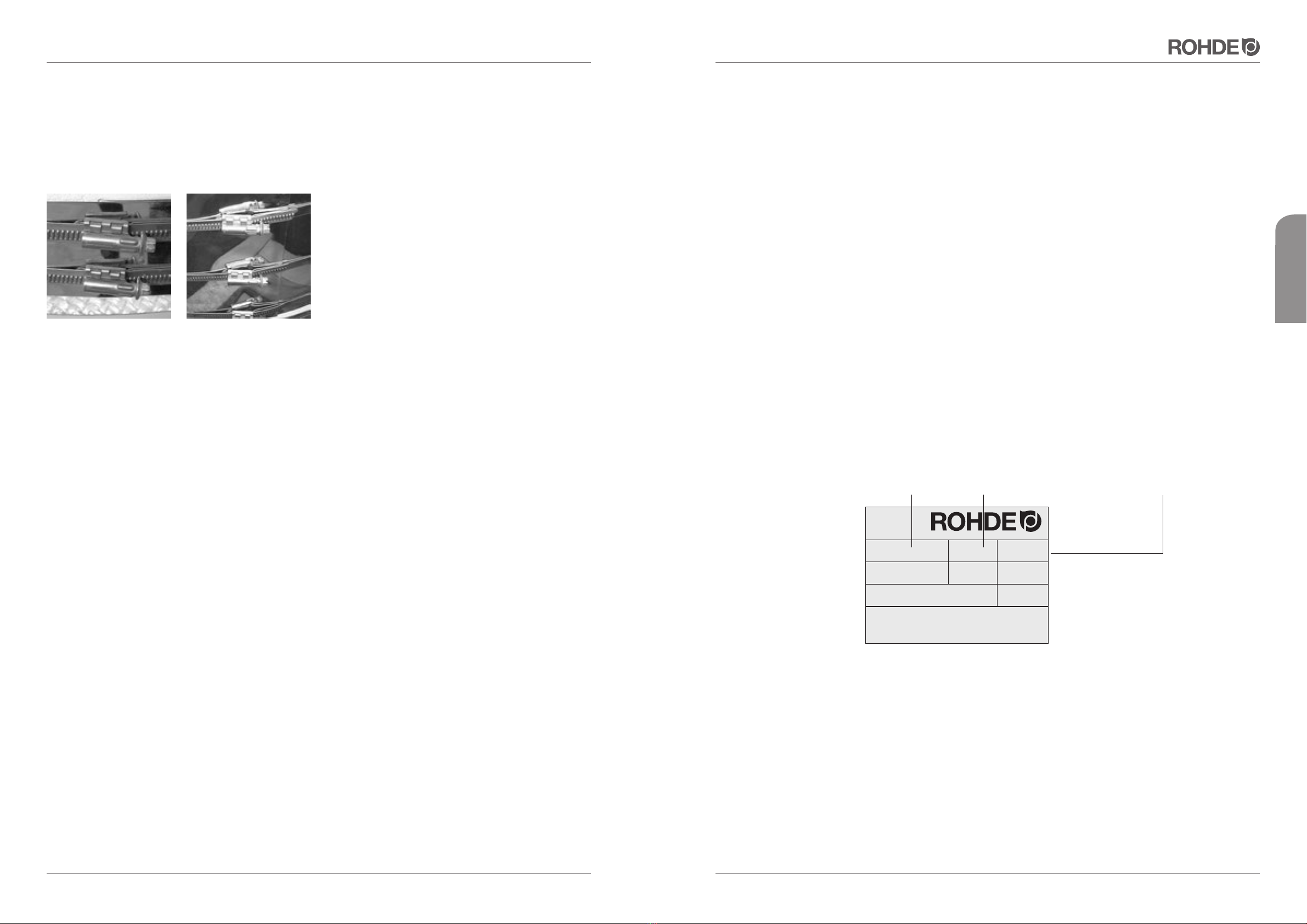
Brennöfen und Maschinen für Keramik, Glas und Metall
Modell / Model:
Maximale Betriebstemperatur /
Maximum operating temperature:
SN:
16 A
1320 °C 50 Hz
7,3 kW
TE 95 S # 32694
3/N/PE AC 400 V
01 / 2013
Spannung /Voltage: Strom / Current: Leistung / Power:
Baujahr /Y. O. M.:
Helmut Rohde GmbH
Ried 9
D - 83134 Prutting
Frequenz:
CE
10. WARRANTY
We guarantee excellent manufacturing and functionality of the kiln and provide a 36-month warranty from date of
invoice.
As well as the heating elements (subject to wear) the following are excluded from the scope of warranty:
• Damage caused by the customer such as broken bricks on the cover caused by placing objects on top of the kiln.
• Damage caused by the fired material, e.g. due to temperature limits being exceeded.
• Damage caused by improper transport.
• Damage due to chemical reactions during firing for which the kiln is not intended (such as salt glaze).
• Corrosion caused by aggressive glazes or insufficient ventilation of the firing chamber. The manufacturer is not liable
for any damage resulting from improper operation and resulting damages.
Important: Please fill in the GUARANTEE CARD and send it back immediately! Please note: If you do not send back
the Guarantee Card, we will not be able provide quick, free support in an event of damage.
PLease note: The firebricks of the kiln lining are exposed to significant temperature fluctuations. This may cause
hairline cracks in the firebrick lining. This process is common and does not affect the functionality of the kiln. It cannot
therefore be accepted as a reason for complaint.
What to do in the case of warranty / damage:
Please notify us - before incurring any costs. After contacting the manufacturer, Helmut Rohde GmbH, your retailer
will then decide how to proceed.
If any claims arise, please state the kiln type, product number and the date of purchase or the year of construction
(see type plate on switch cabinet).
We refer to the General Terms and Conditions (dated 18 December 2006) of Helmut Rohde GmbH.
11. PROPERTY RIGHTS / TRADE NAMES AND DISCLAIMER
The contents of the instruction manual are purely informative. Changes may be made without prior notice and may
not be seen as a liability of Helmut Rohde GmbH. We do not guarantee or accept responsibility for the correctness
or precision of the contents in this instruction manual.
We mention names, trade names, product identifications etc. without special identification, as they are generally
known. Those names and identifications, however, may be the property of companies or institutions and subject to
copyright.
8. MAINTENANCE / CARE AND CLEANING
As the fire bricks give off residual moisture during the first operation the volume of the kiln might change slightly. It is
therefore essential to readjust the tensioning belts of the stainless steel casing of the cover (figure 24) and main ring
(figure 25) after the first firings (not applicable for Quattro and square or rectangular Toploader models).
Please make sure that no clays and glazes come into
contact with the heating elements. This will cause the
heating elements to malfunction during subsequent
firings. If, however, impurities get onto the heating ele-
ments, clean them immediately, as burned-in glazes etc.
will damage the heating elements and bricks. If there is
substantial damage, please contact Helmut Rohde GmbH
or your retailer.
Heating elements are subject to wear. Their resistance (Ohm) increases with every firing. Over the course of time this
will lead to delays in the firing cycle due to a drop in performance, especially in the upper temperature range. If there
is excessive wear we recommend that you replace the complete set of heating elements rather than just single
elements. Replacing individual elements might lead to variations in temperature inside the kiln.
Have a qualified electrician replace the heating elements!
A tip for the firing professional: Always keep a spare set of heating elements! In case of an emergency
this will save you unnecessary delay and allow you to continue firing as quickly as possible.
Remove clay and stone dust regularly using a broom and a vacuum cleaner. This will also increase the service life of
your heating elements.
Avoid reduction glaze firing, as this will cause the oxidation layer to decompose, thus significantly reducing the service
life of the heating elements.
We recommend an empty firing (without furniture or goods) after every 20th firing. This will "clean" the heating ele-
ments and at the same time the oxide layer can renew itself which will extend the service life of the elements.
9. TROUBLESHOOTING TIPS
The controller cannot be switched on.
• Check if the controller has been connected to the switch cabinet of the kiln.
• Check if the kiln is connected to the mains supply.
• Check the micro-fuse on the switch cabinet of the kiln. This has a T 2A fuse.
• Have your house mains supplies (plugs), fuses and the current consumption of your kiln checked by a qualified
electrician.
The controller displays an error message.
You will find the relevant explanation in your user’s manual for the controller.
The firing chamber does not heat up. Check if the cover switch is working. The cover switch is probably not
working and thus cannot operate the safety contactor. Make sure that the safety switch drops back in to the round
hole. If this does not happen, the safety circuit is interrupted and the kiln cannot heat up.
The kiln heats up very slowly. The kiln does not reach the programmed temperatures. The controller displays an
error message. Check the heating elements for visible damage, e.g. cracks.
The functionality of all ROHDE kilns is tested before they leave the factory!
figure 24 figure 25

Page 14 of 16 Level: 02/2013 Level: 02/2013 Page 15 of 16
Enjoy your results
english
12. DECLARATION OF CONFORMITY 13. SPARE PARTS
When ordering spare parts please have your invoice of purchase to hand.
This invoice provides all the relevant data which will allow you to quickly order any spare parts.
14. CONTACTS / ASSISTANCE
If you have any questions regarding your kiln, spare parts and additional equipment, please contact your local dealer.
Enjoy working with your new kiln! We wish you excellent firing results.
Your ROHDE team
Helmut Rohde GmbH · Ried 9· D-83134 Prutting
info@rohde-online.net · www.rohde-online.net
Directive 2006/95/EC
Electrical Apparatus Low Voltage Directive
The Manufacturer Die Firma La empresa
certifies and declares under its sole Erklärt in alleiniger Declara bajo su exclusiva
responsibility that the following Verantwortung, daß folgendes responsabilidad que el siguiente
product: Produkt: producto:
TE Toplader
to which this Declaration of Conformity relates, auf das sich diese Erklärung bezieht, mit al que se refiere la presente declaración está
is in conformity with the following directives and standards: folgenden Richtlinien bzw.Normen conforme con las siguientes directivas y normas:
• Electromagnetic compatibility directive übereinstimmt: • Directiva 2004/108/CE, Compatibilidad
(EMC) (2004/108/EEC) • Richtlinie 2004/108/EG, Elektromag. electromagnética
• Directive 93/68/ECC relating to CE marking Verträglichkeit • Directiva 93/68/ CEE, Denominación CE
• Richtlinie 93/68/ EWG, CE Kennzeichnung
European Standard - Europäische Normen - Normas europeas
EN 60204-1 ed. 2 EN 60439-1 ed. 2 EN 61000-6-4 ed. 2
EN 55011 ed. 2 EN ISO 13732-1 ISO 11684
ISO 7000 EN 60519-1 ed. 2 EN 60519-2 ed. 2
Documentation evidencing Die oben genannte Firma hält La empresa mencionada anteriormente
conformity with the requirements of Dokumentationen als Nachweis der tiene a disposición para inspección los
the Directives is kept available for Erfüllung der Sicherheitsziele und die documentos que confirman el
inspection at the above wesentlichen Schutzanforderungen cumplimiento de los objetivos de
mentioned Manufacturer. zur Einsicht bereit. seguridad y los requisitos de protección
esenciales.
11.04.12
Benjamin Rohde
Managing director - Geschäftsführer - Direttore amministrativo
CZECH REPUBLIC
ROHDE, spol. s.r.o.
67126 Dyjákovice, Dyjákovice 311
EC DECLARATION OF CONFORMITY
EU-KONFORMITÄTSERKLÄRUNG
DECLARACIÓN DE CONFORMIDAD UE
CE
Page 16 of 16 Level: 02/2013
Enjoy your results
français
Mode d'emploi
Fours électriques verticaux pour la céramique jusqu'à 1320°C

Version: 09/2017 Page 3de 16Page 2de 16 Version: 09/2017
Pour le plaisir du résultat
français
1. AVANT-PROPOS
Félicitations: en choisissant un four ROHDE, vous avez opté pour un produit de marque répondant aux exigences les
plus élevées. Ce four vertical est l'aboutissement du perfectionnement intensif de fours à céramique petit et moyen
format. Le résultat en est un four à 1320 °C* doté d'un revêtement intérieur de grande qualité pour les applications
du travail du verre et de la céramique.
Le présent mode d'emploi se propose de vous faciliter la prise en main de votre four vertical ROHDE. Dans cette
optique, nous avons regroupé quelques remarques et directives importantes pour vous permettre d'utiliser votre four
aisément et en toute sécurité. Veuillez lire attentivement le mode d'emploi avant d'utiliser votre four vertical ROHDE
pour la première fois. Apprenez ainsi les principes de fonctionnement de votre four et du système de régulation.
*ATTENTION : la température maximale (Tmax) est différente sur le modèle Ecotop 60 L.
2. FAMILLE DE PRODUITS
*ZWR = anneau intermédiaire pour extension Voltages spéciaux disponibles sur demande pour tous les réseaux de l'UE
SOMMAIRE Page
1. Avant-propos. . . . . . . . . . . . . . . . . . . . . . . . . . . . . . . . . . . . . . . . . . . . . . . . . . . . . . . . . . . . . . . . . . . . . . . 3
2. Famille de produits. . . . . . . . . . . . . . . . . . . . . . . . . . . . . . . . . . . . . . . . . . . . . . . . . . . . . . . . . . . . . . . . . . 3
3. Vue d'ensemble. . . . . . . . . . . . . . . . . . . . . . . . . . . . . . . . . . . . . . . . . . . . . . . . . . . . . . . . . . . . . . . . . . . . . 4
4. Consignes de sécurité importantes. . . . . . . . . . . . . . . . . . . . . . . . . . . . . . . . . . . . . . . . . . . . . . . . . . . . 5
4.1. Remarques générales 5
4.2. Consignes de sécurité . . . . . . . . . . . . . . . . . . . . . . . . . . . . . . . . . . . . . . . . . . . . . . . . . . . . . . . . . . . . . . . . . 5
4.3. Consignes de sécurité pour la mise en œuvre . . . . . . . . . . . . . . . . . . . . . . . . . . . . . . . . . . . . . . . . . . . . . . . 5
5. Mise en service. . . . . . . . . . . . . . . . . . . . . . . . . . . . . . . . . . . . . . . . . . . . . . . . . . . . . . . . . . . . . . . . . . . . . 6
5.1. Livraison et déballage du four . . . . . . . . . . . . . . . . . . . . . . . . . . . . . . . . . . . . . . . . . . . . . . . . . . . . . . . . . . . 6
5.2. Élimination de l'emballage . . . . . . . . . . . . . . . . . . . . . . . . . . . . . . . . . . . . . . . . . . . . . . . . . . . . . . . . . . . . . . 6
5.3. Environnement de service et lieu d'installation . . . . . . . . . . . . . . . . . . . . . . . . . . . . . . . . . . . . . . . . . . . . . . . 6
5.4. Installation du four . . . . . . . . . . . . . . . . . . . . . . . . . . . . . . . . . . . . . . . . . . . . . . . . . . . . . . . . . . . . . . . . . . . . 6
5.5. Installation de l'évacuation d'air . . . . . . . . . . . . . . . . . . . . . . . . . . . . . . . . . . . . . . . . . . . . . . . . . . . . . . . . . . 7
5.6. Trappe d'aération . . . . . . . . . . . . . . . . . . . . . . . . . . . . . . . . . . . . . . . . . . . . . . . . . . . . . . . . . . . . . . . . . . . . . 7
5.7. Branchement au réseau et connexion du système de régulation . . . . . . . . . . . . . . . . . . . . . . . . . . . . . . . . . 7
5.8. Montage mural du système de régulation. . . . . . . . . . . . . . . . . . . . . . . . . . . . . . . . . . . . . . . . . . . . . . . . . . . 8
5.9. Cuisson de rodage du four et du matériel d'enfournement. . . . . . . . . . . . . . . . . . . . . . . . . . . . . . . . . . . . . . 8
5.10. Indications relatives au branchement électrique et au disjoncteur à courant résiduel (RCD) . . . . . . . . . . . . . 8
6. Consignes générales d'utilisation . . . . . . . . . . . . . . . . . . . . . . . . . . . . . . . . . . . . . . . . . . . . . . . . . . . . . 9
6.1 Consignes d'utilisation du système de régulation . . . . . . . . . . . . . . . . . . . . . . . . . . . . . . . . . . . . . . . . . . . . . 9
6.2. Maniement correct pendant la cuisson . . . . . . . . . . . . . . . . . . . . . . . . . . . . . . . . . . . . . . . . . . . . . . . . . . . . 9
7. Autres fonctions . . . . . . . . . . . . . . . . . . . . . . . . . . . . . . . . . . . . . . . . . . . . . . . . . . . . . . . . . . . . . . . . . . . 10
7.1. Transport sur le lieu d'installation . . . . . . . . . . . . . . . . . . . . . . . . . . . . . . . . . . . . . . . . . . . . . . . . . . . . . . . . 10
7.1.1. Démontage du couvercle . . . . . . . . . . . . . . . . . . . . . . . . . . . . . . . . . . . . . . . . . . . . . . . . . . . . . . . . . . . . . . 10
7.1.2. Démontage de l'anneau principal . . . . . . . . . . . . . . . . . . . . . . . . . . . . . . . . . . . . . . . . . . . . . . . . . . . . . . . . 10
7.1.3. Démontage de l'anneau intermédiaire . . . . . . . . . . . . . . . . . . . . . . . . . . . . . . . . . . . . . . . . . . . . . . . . . . . . 10
7.1.4. Démontage du piètement. . . . . . . . . . . . . . . . . . . . . . . . . . . . . . . . . . . . . . . . . . . . . . . . . . . . . . . . . . . . . . 11
7.2. Piètement réversible. . . . . . . . . . . . . . . . . . . . . . . . . . . . . . . . . . . . . . . . . . . . . . . . . . . . . . . . . . . . . . . . . . 11
7.3. Exemple d'enfournement . . . . . . . . . . . . . . . . . . . . . . . . . . . . . . . . . . . . . . . . . . . . . . . . . . . . . . . . . . . . . . 11
8. Maintenance / entretien / nettoyage . . . . . . . . . . . . . . . . . . . . . . . . . . . . . . . . . . . . . . . . . . . . . . . . . . 12
9. Conseils pour la recherche des dysfonctionnements . . . . . . . . . . . . . . . . . . . . . . . . . . . . . . . . . . . . 12
10. Conditions de garantie . . . . . . . . . . . . . . . . . . . . . . . . . . . . . . . . . . . . . . . . . . . . . . . . . . . . . . . . . . . . . 13
11. Droits de propriété industrielle / marques / exclusion de responsabilité. . . . . . . . . . . . . . . . . . . . 13
12. Déclaration de conformité. . . . . . . . . . . . . . . . . . . . . . . . . . . . . . . . . . . . . . . . . . . . . . . . . . . . . . . . . . . 14
13. Pièces de rechange . . . . . . . . . . . . . . . . . . . . . . . . . . . . . . . . . . . . . . . . . . . . . . . . . . . . . . . . . . . . . . . . 15
14. Adresses du S.A.V. . . . . . . . . . . . . . . . . . . . . . . . . . . . . . . . . . . . . . . . . . . . . . . . . . . . . . . . . . . . . . . . . . 15
Modèle Tmax Dimens. int. Dimens. ext. Puissance Ampérage Fiche de Plaques Poids
(mm) (mm) branchement d'enfournement Net
Volume °C l p h L P H kW A mm kg
Ecotop 20 1320 ø 330 230 560 560 520 2,3 10,0 Schuko ø 310 49
Ecotop 43 L 1320 ø 400 340 650 700 630 2,9 13,0 Schuko ø 350 72
Ecotop 50 1320 ø 400 380 650 700 725 3,6 16,0 Schuko ø 350 76
Ecotop 50 S 1320 ø 400 380 650 700 725 4,5 6,5 CEE 16 A ø 350 76
Ecotop 60 L 1200 ø 400 450 650 700 740 2,9 13,0 Schuko ø 350 85
Ecotop 60 1320 ø 400 450 650 700 740 3,6 16,0 Schuko ø 350 85
Ecotop 60 S 1320 ø 400 450 650 700 740 5,0 10,0 CEE16A ø 350 85
Modèle Tmax Dimens. int. Dimens. ext. Puissance Ampérage Fiche de Plaques Poids
(mm) (mm) branchement d'enfournement Net
Volume °C l p h L P H kW A mm kg
TE 75 MCC+ 1320 ø470 460 720 740 800 6,0 13 CEE 16 ø420 101
ZWR75 MCC+ ø470 230 650 700 230 3,0 - - - 23
TE 110 MCC+ 1320 ø470 690 720 740 1030 9,0 13 CEE 16 ø420 123
TE100 MCC+ 1320 ø520 460 800 830 800 7,0 15 CEE 16 ø470 110
ZWR100 MCC+ ø520 230 800 830 230 3,5 - - - 22
TE150 MCC+ 1320 ø520 690 800 830 1030 10,5 15 CEE 16 ø470 130
TE130 MCC+ 1320 ø590 460 830 880 800 7,3 16 CEE 16 ø550 110
ZWR130 MCC+ ø590 230 830 880 230 3,7 - - - 25
TE190 MCC+ 1320 ø590 690 830 880 1030 11,0 16 CEE 16 ø550 150
TE200 MCC+ 1320 ø740 460 1000 1050 800 9,2 20 CEE 32 à taille 160
ZWR200 MCC+ ø740 230 1000 1050 230 4,6 - - - 32
TE300 MCC+ 1320 ø740 690 1000 1050 1030 13,8 20 CEE 32 à taille 190
Modèle Tmax Dimens. int. Dimens. ext. Puissance Ampérage Fiche de Plaques Poids
(mm) (mm) branchement d'enfournement Net
Volume °C l p h L P H kW A mm kg
TE 80 S 1320 ø 450 460 770 780 780 6,0 13 CEE 16 ø 420 115
ZWR 80 S ø 450 150 770 780 150 3,0 - - - 20
TE 100 S 1320 ø 450 610 770 780 930 9,0 13 CEE 16 ø 420 145
TE 95 S 1320 ø 520 460 850 800 775 7,0 16 CEE 16 ø 470 153
ZWR 95 S ø 520 230 850 800 230 3,5 - - - 35
TE 145 S 1320 ø 520 690 850 800 1000 10,5 16 CEE 16 ø 470 142
TE 130 S 1320 ø 610 460 950 950 770 8,8 19 CEE 32 ø 550 135
ZWR130 S ø 610 230 950 950 230 4,4 - - - 33
TE 200 S 1320 ø 610 690 950 950 1000 13,2 19 CEE 32 ø 550 190
TE 165 S 1320 730 630 460 1050 950 790 10,0 22 CEE 32 à taille 166
ZWR165 S 730 630 230 1050 950 230 5,0 - - - 36
TE 250 S 1320 730 630 690 1050 950 1020 15,0 22 CEE 32 à taille 222
TE 300 S 1320 830 630 690 1160 950 1020 15,0 22 CEE 32 à taille 225
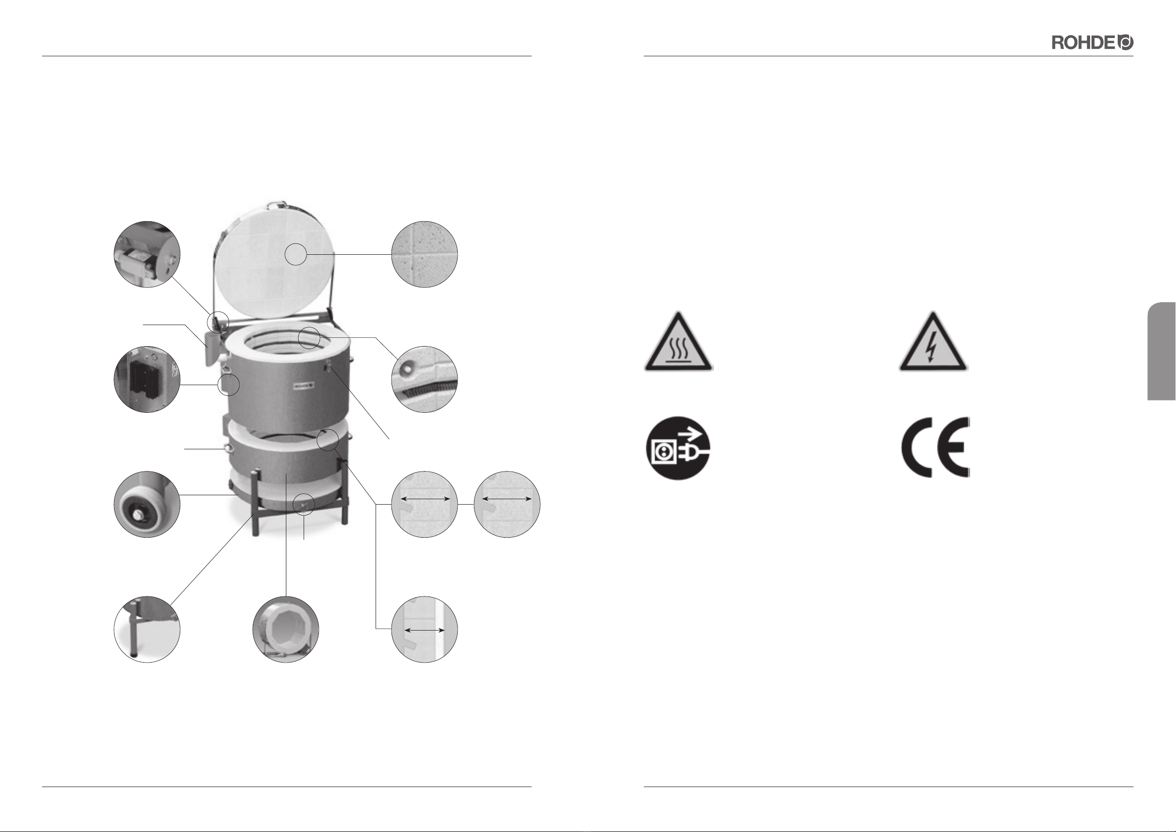
Version: 09/2017 Page 5de 16Page 4de 16 Version: 09/2017
Pour le plaisir du résultat
français
4. CONSIGNES DE SÉCURITÉ IMPORTANTES
4.1. Remarques générales
Respectez impérativement les consignes de sécurité, mais aussi le marquage de sécurité afin d'exclure tout danger.
Dans votre propre intérêt, veuillez lire intégralement les consignes de sécurité suivantes avant de mettre le four en
service.
Veuillez conserver soigneusement le présent mode d'emploi. Pour votre propre sécurité, n'utilisez que les pièces de
rechange ROHDE!
La société Helmut Rohde GmbH décline toute responsabilité pour les dommages causés par les résistances inap-
propriées ou défectueuses d'autres fabricants. Le montage d'autres pièces de rechange que celles d'origine entraîne
également la déchéance de tous les droits de recours en garantie!
4.2. Consignes de sécurité
Attention: surface chaude,
ne pas ouvrir à chaud.
Attention: retirer la fiche secteur
avant d'ouvrir le boîtier électrique!
(directive des caisses profession-
nelles allemandes d'assurance-
accidents «BGV A8»)
Attention: mise en garde contre une
tension électrique dangereuse.
Le marquage CE confirme que la
procédure d'évaluation de la confor-
mité a été appliquée suivant les
directives européennes suivantes:
Directive 2004 / 108 / CE
Directive 93 / 68 CEE, marquage CE
4.3. Consignes de sécurité pour la mise en œuvre
Le four ROHDE ne peut être utilisé sans danger que si les consignes de sécurité suivantes sont respectées:
• Si le four et le système de régulation sont mis en œuvre dans une entreprise artisanale, commerciale ou industrielle,
un électricien qualifié doit contrôler avant leur première mise en service puis tous les 4 ans (suivant la directive des
caisses professionnelles allemandes d'assurance-accidents « BGV A3 Contrôle ») s'ils sont en parfait état et con-
formes à la réglementation.
• Seul un électricien qualifié sera autorisé à effectuer les travaux de réparation et d'entretien sur les composants
électriques.
• Pour des raisons de sécurité, il faut retirer la fiche secteur avant les travaux d'entretien.
• L'utilisation de rallonges n'est pas autorisée!
3. VUE D'ENSEMBLE
Assemblage du couvercle sans mortier
Ancrage mécanique des briques pour éviter
leur glissement,
Chanfrein réduisant les chutes de particules
Tous les modèles sont démontables,
certains peuvent recevoir une extension
Pied réversible ROHDE
Roulettes de transport
équipant les pieds arrière
(TE 20 – 110)
Trappe d'aération sur
tous les modèles
verticaux
Structure des parois de la série verticale
artisanale TE-MCC+
Structure des parois
de la série verticale
professionnelle TE-S
Structure des
parois de la série
verticale Ecotop
Fermeture du couvercle
réglable et verrouillable
Relais à semi-conducteurs (SSR)
de série sur tous les modèles
TE-S et Ecotop
Disjoncteur de protection
à courant de défaut
Manchon de
sortie d'air
Poignées de transport
métalliques
Fixation précise des résistances,
Installation protégée du
thermocouple
Usinage précis des bords
des briques
Ouverture large et facile du couvercle, positionnement
stable
Charnière de couvercle très robuste,
ouverture assistée par des vérins à gaz
114mm 110mm
95mm
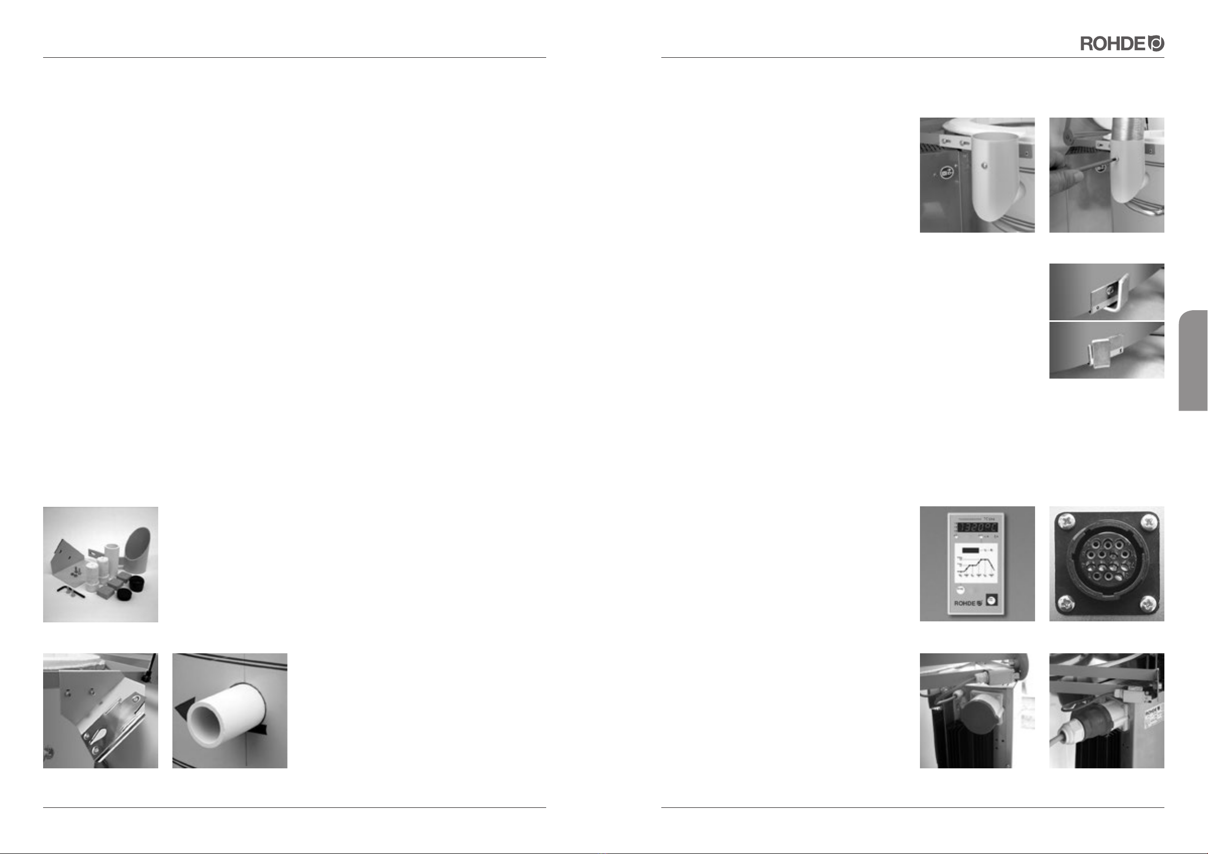
Version: 09/2017 Page 7de 16Page 6de 16 Version: 09/2017
Pour le plaisir du résultat
français
5.5. Installation de l'évacuation d'air
Attention: le manchon de sortie d'air a été conçu de
manière à ce que la chaleur émise ne puisse rayonner sur
les parois, les surfaces ou les objets. Si le manchon de
sortie d'air est monté sur le four, le trou d'évacuation d'air
ne peut être bouché.À l'inverse, si vous voulez boucher
le trou d'évacuation d'air pendant la cuisson, le manchon
ne doit pas être vissé à cet endroit.
Vissez le manchon de sortie d'air fourni avec l'équipement
(photo 4) dans le trou prévu à cet effet sur la face latérale
gauche du four. L'endroit prévu pour la fixation a été choi-
si de manière à permettre l'évacuation des vapeurs et gaz
par le biais d'un tuyau flexible d'évacuation d'air (acces-
soire en option). Le tuyau flexible d'évacuation d'air
s'insère dans le manchon de sortie d'air (figura 5) et se
fixe avec la vis de fixation dans le manchon.
5.6. Trappe d'aération
Tous les modèles de four vertical ROHDE sont équipés d'une trappe d'aération (figura
6) au niveau de la sole. Lorsque la trappe d'aération est positionnée à gauche, l'admission
d'air est coupée. Si la trappe pointe vers la droite, l'admission d'air est ouverte.
Le fait d'ouvrir l'admission d'air jusqu'à une température d'env. 600 à 700°C
permet de prolonger considérablement la durée de vie des résistances.
5.7. Branchement au réseau et connexion du système de régulation
Le four est équipé d'un câble permettant de le raccorder au réseau. Vous pouvez relever les caractéristiques corres-
pondantes sur la plaque signalétique. L'alimentation électrique doit être dimensionnée en adéquation avec le four et
se trouver à proximité immédiate de celui-ci. N'utilisez
jamais de rallonges! Le câble d'alimentation ne do-
it pas toucher les parois chaudes du four.
Des variations locales de tension sont possibles. En Alle-
magne, la tension nominale de 230 / 400V peut varier
de 10 %. Ceci entraîne des écarts en termes de puis-
sance nominale. Si la tension chute à 210V en charge,
la puissance du four baisse alors d'env. 16 %.
Le système de régulation (photo 7) se couple au four par
le biais d'un connecteur 14 broches à enficher et visser.
La prise de courant noire prévue à cet effet sur le four
(figura 8) se trouve à côté du câble d'alimentation élec-
trique sur la face latérale du boîtier de connexion.
Enfichez d'abord la fiche noire du système de régulation.
Vous devez éventuellement la tourner un peu jusqu'à ce
qu'elle s'enclenche. Serrez ensuite la bague de vissage
à fond pour bloquer la fiche.
Tous les fours susceptibles de recevoir une extension
sont déjà équipés (photo 9) des raccords nécessaires
pour l'extension (photo 10).
photo 4 photo 5
photo 7 photo 8
photo 9 photo 10
photo 6
5. MISE EN SERVICE
5.1. Livraison et déballage du four
Si le four vertical ROHDE vous est livré sur palette par une entreprise de transport, vérifiez immédiatement à la livrai-
son si l'emballage présente des dommages apparents. Dans l'affirmative, déballez la palette avec le livreur et vérifiez
à nouveau si la marchandise est endommagée. Le cas échéant, notez immédiatement les dommages sur le bon de
livraison et faites-le impérativement contresigner par le livreur. Conservez une copie de votre réclamation pour dom-
mages. Signalez immédiatement les dommages à l'entreprise de transport. Toute réclamation ultérieure sera vaine.
5.2. Élimination de l'emballage
Apportez les emballages en bois, carton et film plastique à un centre d'élimination des déchets approprié et partici-
pez ainsi activement à la protection de l'environnement.
Pour plus d'informations en ce qui concerne l'élimination des emballages, veuillez-vous adresser à votre revendeur
ou aux services administratifs de votre commune ou de votre ville.
5.3. Environnement de service et lieu d'installation
Choisissez un lieu d'installation approprié et respectez impérativement les règles suivantes pour préparer la mise en
place:
• Placez le four sur une surface plane.
• L'écartement entre le four et les murs doit être d'au moins 25 cm de tous côtés.
• Le sol, l'isolation du plafond ainsi que les murs, cloisons, revêtements, etc. doivent être réalisés en matériau ignifuge.
• Veillez à ce l'on puisse bien aérer le lieu d'installation.
• Il faut sinon installer un équipement d'évacuation d'air.
• À cet effet, consultez en tout état de cause un technicien spécialisé en ventilation.
5.4. Installation du four
Contrôlez d'abord les accessoires livrés avec le four (photo 1):
• 3 petits blocs de cordiérite (6 petits blocs sur les modèles TE 165 / 250 et TE 300)
• 1 tuyau d'évacuation d'air en céramique
• 2 bouchons
• 1 embout en plastique pour le pied du four
• 1 pied de rechange en plastique
• 1 manchon de sortie d'air avec vis de fixation
• 1 plaque de montage pour le système de régulation avec vis de fixation
Le système de régulation et son mode d'emploi ainsi que
le mode d'emploi du four sont également joints à la four-
niture.
Montez d'abord la plaque de montage du système de
régulation (photo 2) au niveau des trous de l'arceau du
couvercle prévus à cet effet.
Sortez ensuite le tuyau de céramique du carton et insérez-
le dans le trou d'évacuation d'air (photo 3) ménagé dans
la face latérale gauche du four.
photo 2
photo 1
photo 3
Other manuals for TE Series
1
This manual suits for next models
25
Table of contents
Languages:


