Rolls LFP ESS User manual

Rolls LFP ESS Cabinet Assembly Instructions

Ver 1.0 09-23
2
Introduction
The optional Rolls LFP ESS Cabinet may be used to install Rolls 19" rack compatible LFP ESS
batteries. The cabinet package is available for use with 2U, 3U or 4U battery models and provides
a safe and secure enclosure, with locking and levelling casters for stationary installation. If casters
are not useable due to earthquake-specific or other code requirements, please enquire about
alternative options.
The standard 4 x 4U cabinet package includes modular components for the installation of four (4)
19” 4U rack compatible LFP batteries. This Rolls LFP ESS Cabinet is expandable up to 32U height
or eight (8) x 4U batteries with the addition of four modular 4U cabinet segments. Rolls LFP ESS
Cabinet components, including additional segments, are available for purchase from authorized
Rolls Battery distributors & dealers.
To ensure safe operation, please read the following instructions carefully before assembly.
Appearance

Ver 1.0 09-23
3
Components
CODE
DIAGRAM
DESCRIPTION (Qty)
1
Cabinet bottom assembly w/
locking & leveling casters (1)
2
Left column (8)
3
Right column (8)
4
Tray (3)
5
LFP Battery (19” 4U)
(not incl)
6
Combiner Box (2)
7
Side plate (6)
8
Front panel (4)
9
Rear panel (4)
10
Cabinet top (1)

Ver 1.0 09-23
4
Accessories List
CODE
DIAGRAM
DESCRIPTION (Qty)
A
Positive parallel cable (red)
B
Negative parallel cable (blk)
C
RJ45 comm parallel wires (3)
D
Input positive cable (red)
E
Output negative cable (blk)
F
RJ45 CAN
communication 1m (1)
G
RJ45 CAN
communication 2m (1)

Ver 1.0 09-23
5
Assembly
Figure 1.0
To begin the cabinet assembly:
1.1 Install two left Cand two right Dcolumns into the cabinet bottom
assembly as shown in Figure 1.0. Fasten at the base of each column
using three of the supplied 10mm M5 screws.
1.2 Install the supplied left & right mounting brackets on the front of the
Rolls LFP ESS battery. Place the battery Fbetween the columns as
shown and secure using two 12mm M6 hex bolts in each of the front
mounting brackets.
1.3 With the battery installed, repeat step 1.1, installing the next four
columns.

Ver 1.0 09-23
6
Figure 2.0
Install the tray Eas shown in Figure 2.0, locking the tabs into place on each of
the four columns to secure.
1.4 Install the 2nd Rolls LFP ESS battery Fon the tray and fasten on each
side using two 12mm M6 hex bolts as outlined in step 1.2.
Repeating steps 1.1 through 1.4 for each additional battery.
Parallel Connection
Rolls LFP ESS Cabinet includes two combiner boxes used to connect each battery
in parallel. Positive input & negative output cabling is connected to the corresponding
combiner box and run through the rear of the cabinet top assembly.
The combiner box is designed for 8AWG wire inputs which should be the same length for
all batteries to ensure proper current sharing. Due to the secondary breaker protection at
each battery, additional fusing is optional from battery to combiner box. Always refer to
local code requirements for required installation practices when installing additional fuses
and wiring.

Ver 1.0 09-23
7
The use of combiner boxes is preferred but optional. Alternatively, when connecting
Rolls LFP ESS batteries in a standard racking system, each battery may be
connected in parallel using cables or bus bars of equal length and size.
Refer to the Rolls S48-100LFP ESS Battery Operating Manual for detailed
instructions.
Figure 3.0
1.5 When all batteries have been installed, fasten a combiner box Gto the
included mounting plate with the single output port facing up using M4
half-round Philips screws. Repeat for the 2nd combiner box. Mount the
combiner boxes on the left and right sides of the cabinet trays using the
supplied M4 half-round Philips screws as shown below in Figure 3.0.
INPUT
OUTPUT

Ver 1.0 09-23
8
With the batteries and combiner boxes assembled, the parallel cabling and
communication may now be connected.
Note: Before connecting any wiring, ensure the main breaker switch on each battery
is set to OFF.
Figure 4.0
1.6 Connect the cabinet wiring in the following order:
A. When using the included combiner boxes, connect a positive parallel
cable
A
to one of the positive terminals of each battery. Install the
other end of each cable into one of the input ports on the bottom of
the combiner box Gon the left (positive) side of the cabinet. Repeat
F
C
C
C

Ver 1.0 09-23
9
the same process using a negative parallel cable
B
for each of the
negative terminal connections, connecting to the negative combiner
box Gon the right side of the cabinet.
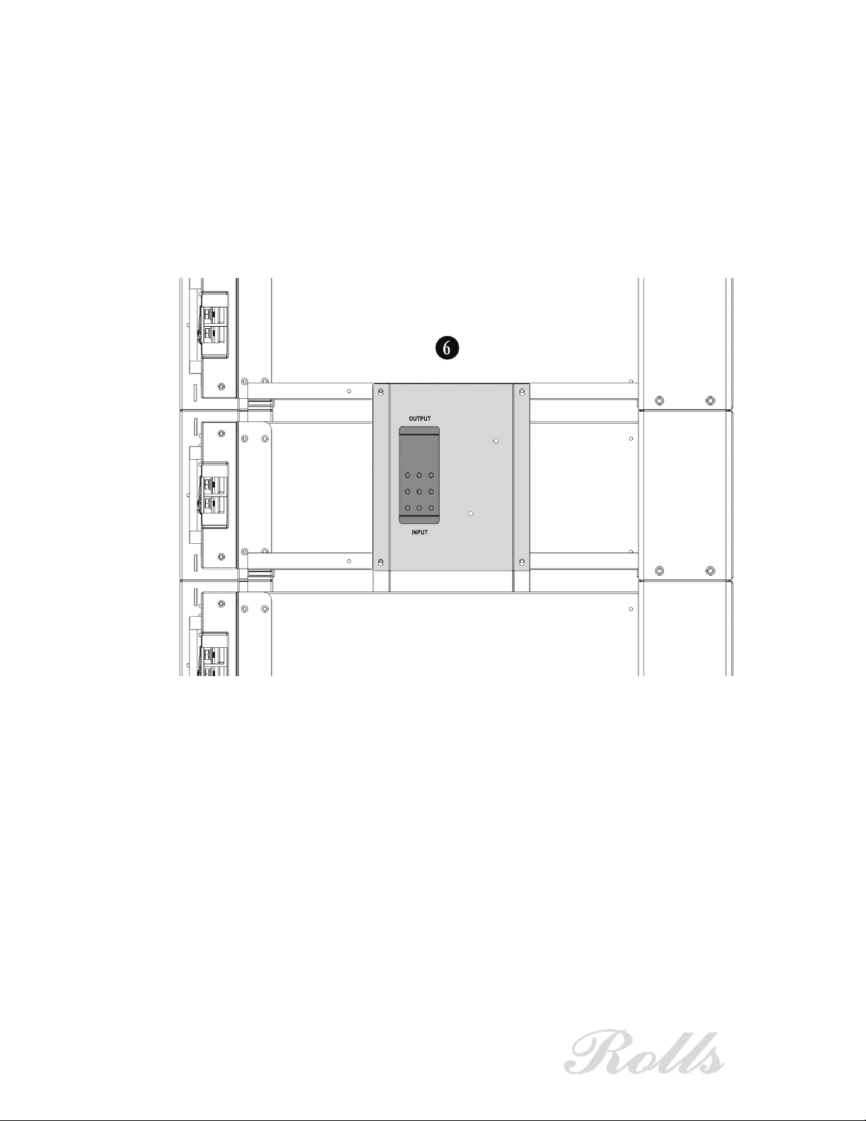
B. Connect the positive input cable
D
to the output port on the top of
the left (positive) combiner box as shown. Connect the negative
output cable
E
to the output port of the negative combiner box.
C. Beginning at the bottom of the cabinet, insert a parallel
communication cable
C
into one of the RS-485 ports on the front of
the battery (either port). Insert the other end of the cable into a RS-
485 port (either port) in the next battery. Insert another parallel
communication cable
C
into the other RS-485 port in the second
battery and connect to the next battery. Repeat this process until all
batteries are connected in parallel as shown in Figure 4.0 above.
D. Connect the 1m RJ45 Communication cable
F
into the available
RS-485 port on the battery installed at the top of the cabinet as
shown in Figure 4.0. Connect the other end of the cable to the RS-
485 port on the underside of the cabinet top assembly. K
1.7 Run the positive input cable
D
and negative output cable
E
through
the marked ports at the rear of the cabinet top assembly. K
1.8 To install the side panels H on each side of the cabinet, position the
panel over the front and rear columns and slide each panel down with
the interlocking tab facing down. Three (3) panels will be installed on
each side of the cabinet. Secure the panels with the supplied M4
countersink Philips head screws, two at the front of the cabinet and two
at the rear.
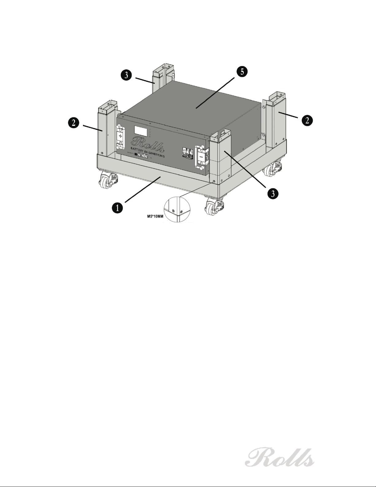
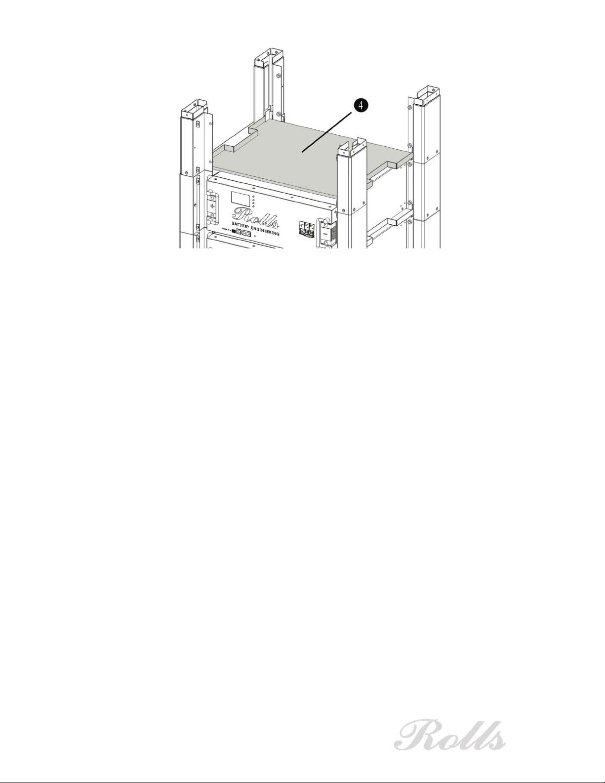
1.9 With the side panels installed, place the cabinet top assembly Kon the
top 4 columns and secure using two of the supplied 10mm M5 screws
on each column as shown in Figure 5.0.

Ver 1.0 09-23
10
Figure 5.0
1.10 Last, the four front panels Iand four rear panels Jattach to the
cabinet assembly with the integrated magnets as shown in Figure 6.0.
These panels provide protection and are easily removed to allow access
to the front or rear of each battery.
Figure 6.0
K

Ver 1.0 09-23
11
Connect to an Inverter
With the batteries installed and wiring connected, the Rolls LFP ESS cabinet may
then be connected to an inverter and powered on using the input/output cables and
2m RJ45 Communication cable
G
as shown in Figure 7.0.
Figure 7.0
1.11 Connect the positive input cable
D
and the negative output cable
E
to
the inverter. Once connected, tighten the PG waterproof ports at the top
of the cabinet to secure the cables.
1.12 Connect the 2m RJ45 CAN communication
G
to the RS-485 port on
the top of the cabinet. Connect the other end of the cable to the CAN
port on the inverter.
Note: the supplied RJ45 CAN communication cable
G
may not be compatible with all
inverters. To connect, refer to your inverter manufacture and/or manual for further
instruction.
Before powering on, refer to the Rolls S48-100LFP ESS Battery Operating Manual for
detailed instructions.
G
D
E
This manual suits for next models
1
Table of contents
Other Rolls Batteries Pack manuals