ROOFLIGHT COMPANY neo Advance Skywalk User manual

www.therooightcompany.co.uk
info@therooightcompany.co.uk |01993 833155
Trusted by architects, respected by builders, loved by homeowners.
Installation Guide
neo Advance SkywalkTM Rooight
LA032-A Form QD334 Revision 1 Date Created May 21 Last Reviewed June 21

INTRODUCTIONINTRODUCTION
Thank you for choosing the neo Advance Skywalk™ rooflight, we are sure it will provide a high-quality
finishing touch to your project. This is a step by step guide to installing the neo Advance Skywalk™ and
neo Advance Skywalk™ + walk-on rooflights.
The step-by-step process must be followed in numerical order to ensure the installation is correct. Every
project is different therefore it may be necessary to adapt the installation to suit the structure.
What you need to know about theWhat you need to know about the neo Advance Skywalk™::
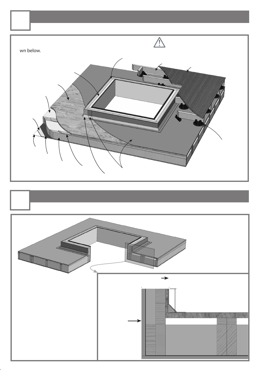
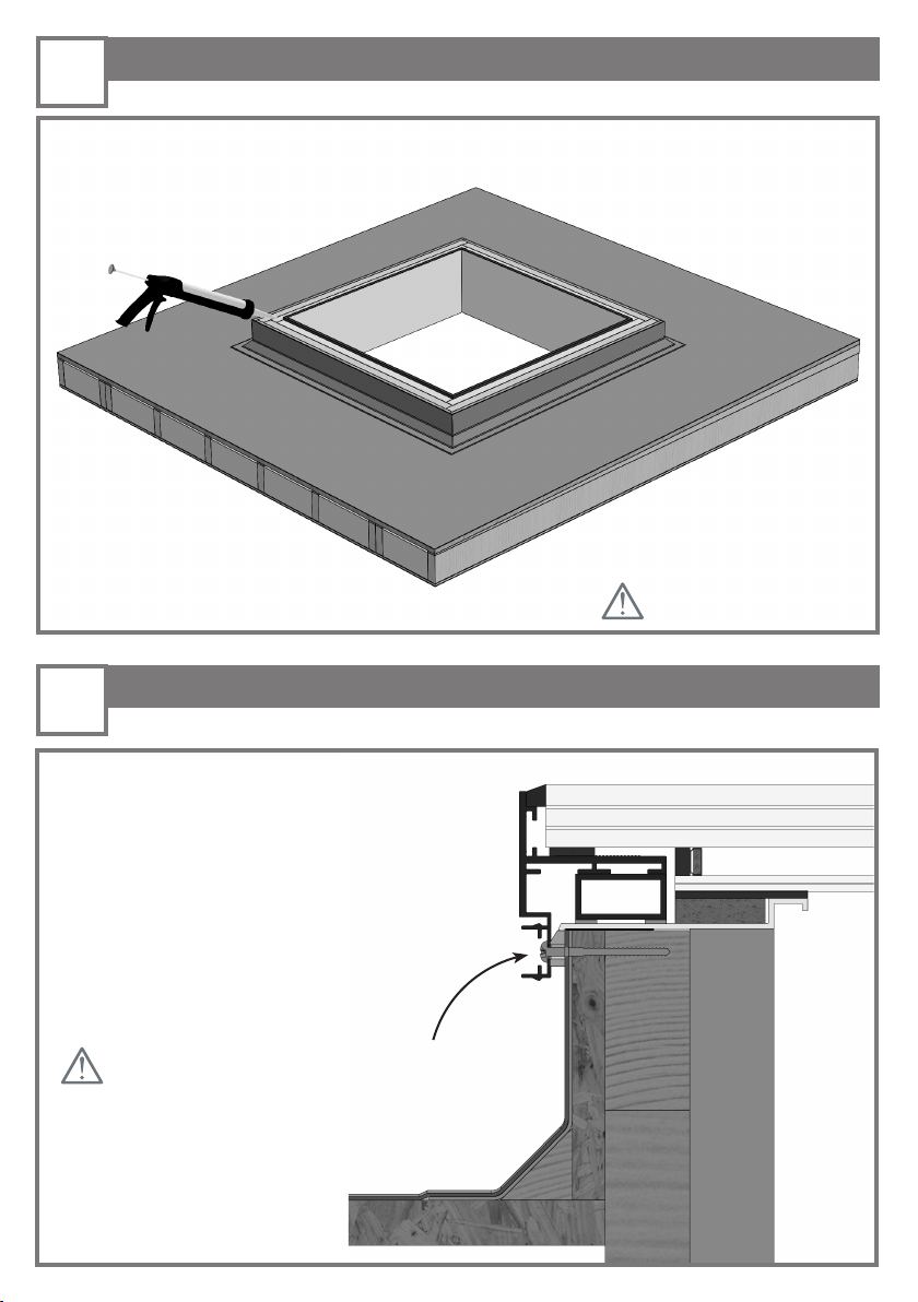
- It should be installed in plane with the finished walk-on surface ensuring there is no potential for water
pooling.
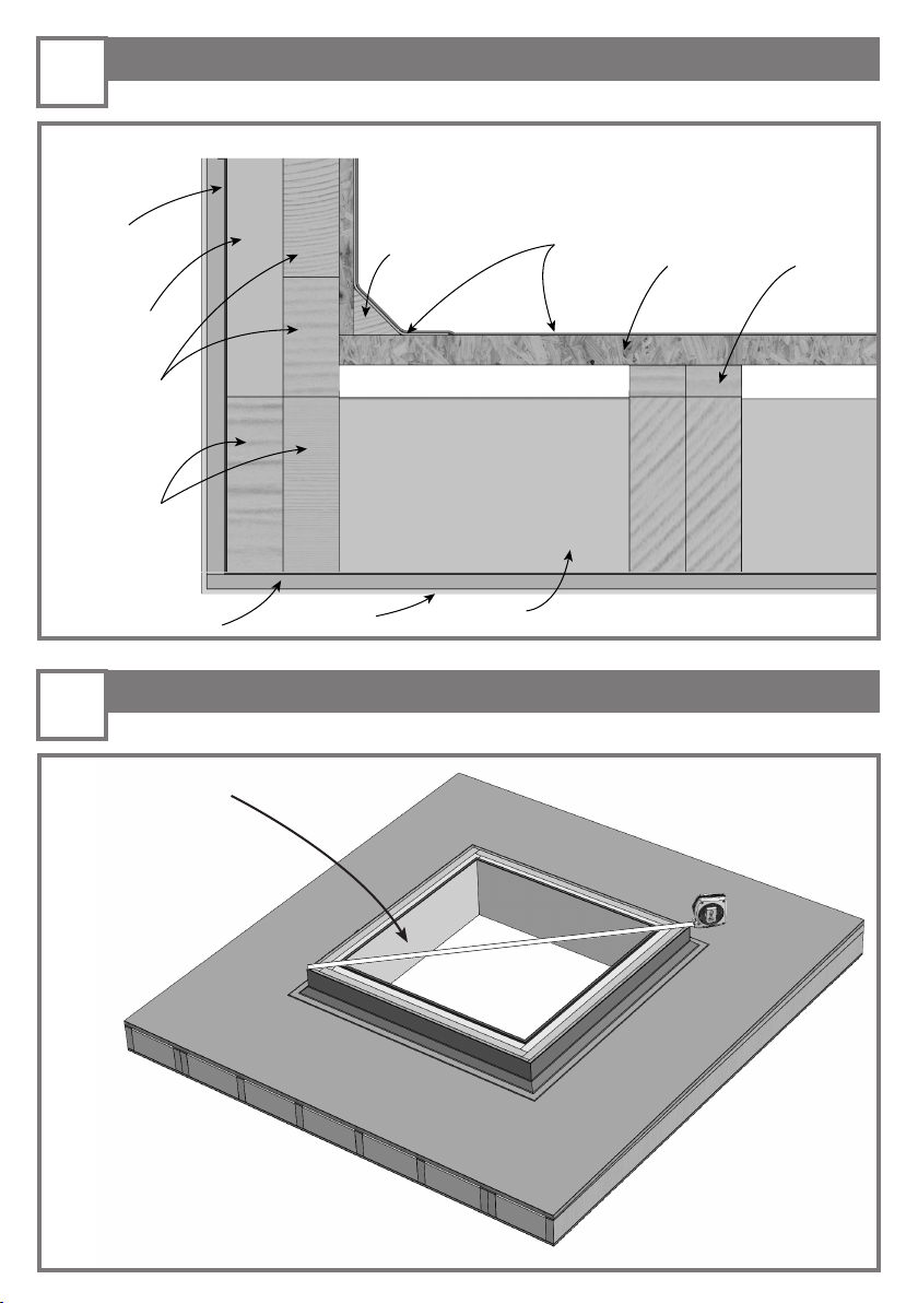
- The following installation details pertain to a timber deck over a membrane roof finish, installed on an
insulated timber kerb.
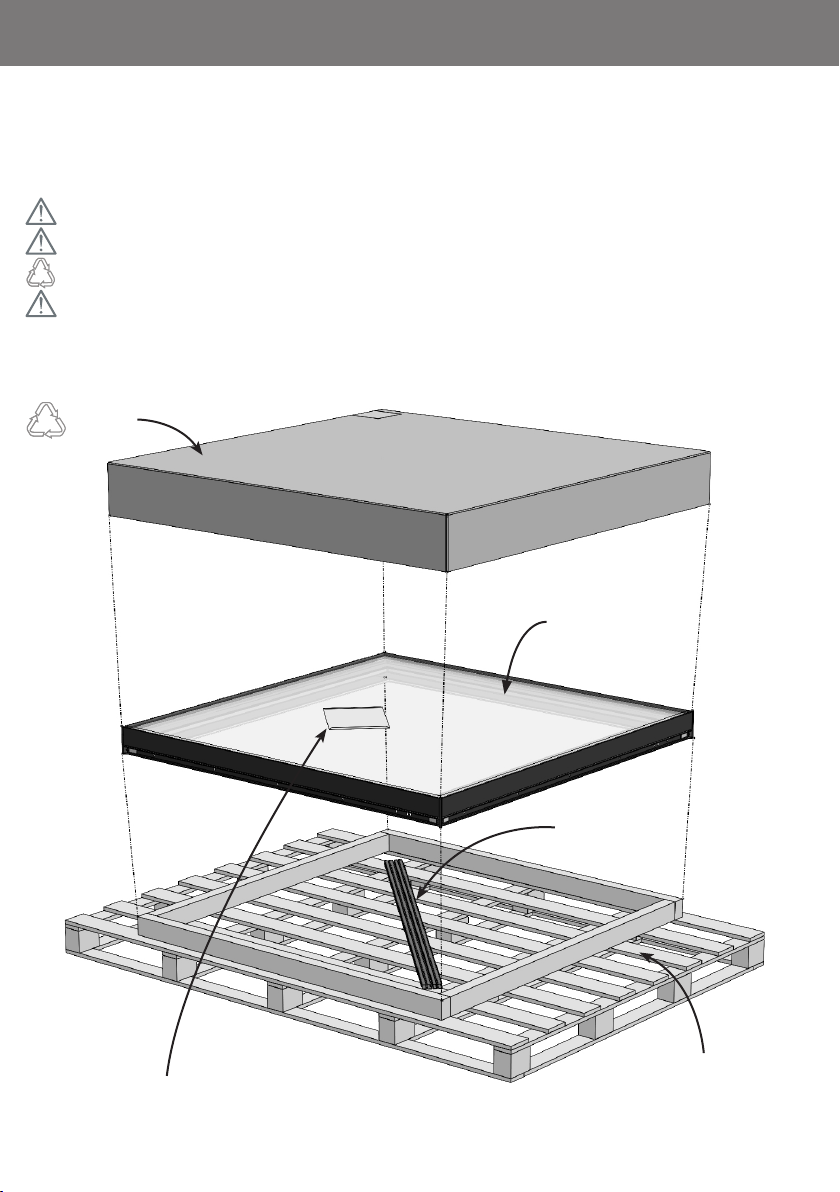
All of the images in this guide are diagrammatic (with some components omitted for clarity). They
should be used as a reference. Installation instructions are regularly reviewed and we reserve the right
to update or amend these details without alteration to this guide.
CARE AND MAINTENANCE
To achieve the maximum service life from the neo Advance Skywalk™ rooflight it is important that
scheduled care and maintenance is undertaken. Please note that the guarantee will become void if the
procedures outlined in this manual and the separately supplied maintenance manual are not adhered
to. Please refer to the Operations and Maintenance Guide for further details.
ADVISORY
Standard rooflight. All the information provided in this document refers to a standard
specification neo Advance Skywalk™ rooflight.
Install in accordance with national building regulations / codes. This manual is an installation
suggestion and installers should verify ‘fitness for purpose’ in accordance with all applicable
regulations / standards at time of installation.
Structural supports for the neo Advance Skywalk™ rooflight are to be
designed and supervised during construction by the rooflight installer or project structural
engineer. Nothing in this manual constitutes a structural proposal. Sizing / positioning of
structural supports should be determined by the projects suitably qualified structural engineer.

WHAT’S IN THE BOXWHAT’S IN THE BOX
Box Lid
neo Advance
Skywalk™
Rooflight(3- ply)
Fixing Kit & Installation Manual
Inside the box you will find your neo Advance Skywalk™ rooflight, the rooflight fixing kit and a
printed copy of this installation manual.
Ensure you check the rooflight for any damage PRIOR to commencing the installation.
Report any damage to the courier and inform the Rooflight Company.
Please recycle the cardboard box appropriately.
We recommend you retain the installation manual for future reference.
Clip Covers
Pallet with kerb

IMPORTANT SAFETY INSTRUCTIONSIMPORTANT SAFETY INSTRUCTIONS
DECLARED PRODUCT PERFORMANCE
Tested to Category A1 of UK National Annex Table NA.2 of BS EN 1991-1-1:2002
(Eurocode 1: Actions on structures – Part 1-1: General actions – Densities, self-weight, imposed
loads for buildings) – where:
Maximum uniformly distributed load (UDL) = 1.5kN/m ²
Maximum concentrated (imposed) load = 2.0kN
Tested to BS 7976-2:2002+A1:2013 (Pendulum testers. Method of operation) where slip
resistance:
Slide 55 (barefoot)
Avg. PTV Dry : 98 Avg. PTV Wet : 37
Slider 96 (typical shoe sole)
Avg. PTV Dry : 66 Avg. PTV Wet : 47
The soft body impact test uses a 300mm diameter cylindrical bag filled with sand with a mass of
45kg. Dropped from a height of 1200mm, producing an impact energy of at least 530J.
The hard body impact test uses a 100mm diameter steel ball with a mass of 4.11kg dropped from
a height of 1200mm producing an impact energy of 48J.

SAFETY NOTICES
Danger of death. Do not use the neo Advance Skywalk™ if the glazing is broken.
Should glass breakage occur cease use immediately and ensure no further usage
of the product can take place. Contact the Rooflight Company for remedial support
on +44(0)1993 830 613.
Danger of death. Do not subject the neo Advance Skywalk™ to loadings greater
than those stated in the declared performance section of this manual.
Danger of slipping. Slip resistance of the neo Advance Skywalk™ will be reduced
if the outer glass face becomes contaminated with lower-friction
contaminants e.g.oil / grease / liquid soap / algae. Follow the maintenance instruc-
tions and ensure the outer glass face is clean and free of all contaminants / debris.
Do not clean the product with harsh or abrasive chemicals – this can impede the
performance of the slip resistant coating and be detrimental to sealants, paint cover-
ing and glass interlayers.
INTENDED USES
As per the declared product performance – the neo Advance Skywalk™ is designed
for domestic applications only in line with the maximum stated uniformly distributed
and concentrated loads.
The slip resistance performance when wet is based on water as the liquid. Should
other liquids contaminate the outer surface of the glazing this may impair the stated
slip-resistance performance value.

1. Step 1 - Preparing the structure
3. Step 3 - Kerb dimensions
A
A1 SECTION VIEW A-A1
*All Components detailed are supplied by others.
1a. Prepare the roof structure and opening to your
preferred specication. An example structure is
shown below.
Finished
internal kerb
Finished external kerb
Kerb width
Kerb height
3a. The kerb width (including
internal nish and external covering)
must be no greater than
130mm. See detailed installation
in Appendix A for more information.
3b. The kerb height should be
constructed in accordance with
the guidance provided in BS6229.
Deck must be installed after rooight.
Timber upstand insulation*
Decking
Decking joists*
Kerb upstand insulation*
Roof deck*
Insulation*
Plasterboard*
Plaster skim*
Vapour barrier*
Ceiling joists*
Firrings*
Timber llet*
Membrane*
Adjustable
decking feet*

4.
Step 2 - Sectional reference details
Step 4 - Levels and falls
2.
Timber llet* Membrane*
Roof deck* Firrings*
Insulation*
Plaster skim*
Plasterboard*
Doubled ceiling
joists*
Timber kerb
upstand*
Kerb upstand
insulation*
Vapour barrier*
2a. The example structure detailed in step 1 is shown below in 2D sectional view.
* All components detailed are supplied by others.
4a. Measure kerb across corners to check
dimensional accuracy.
4b. Ensure kerb top is in plane with the nished
walk-on surface.
Ventilation path (if required)

Step 5 - Silicone sealing
Step 7 - Fixing the rooflight
5.
7.
6a. Apply a generous bead of silicone sealant
to the top face of the kerb prior to lowering the
rooight into place.
We recommend low modulus
neutral cure silicone sealant.
8a. Drill pilot holes into the timber kerb through the
pre-drilled holes in the rooight frame xing channel.
8a. With packers in place behind the xing channel, secure
the rooight frame using the wood screws provided.
Do not overtighten screws or deform the rooight frame.
Ensure packer is in place before tightening screws.

6.
8.
Step 6 - Product position and orientation
7a. Ensure the side of the rooight with
the ‘Cill’identication sticker applied, is at
the lower end of the roof fall.
7b. Lower the rooight frame on to the kerb
upstand ensuring an even gap to all sides.
Ensure cill of rooight is orientated at the lower end of the kerb fall.
Step 8 - Fitting the cover trim
The cover trim has a top and bottom face - please take note of the orientation when
attaching the trim proles.
9a. Push the cover trim on to the frame. An audible‘click’ will be heard when fully
tted. Press along the entire length of the trim to ensure it is fully engaged onto the
rooight frame.
9b. Repeat for all four sides of the rooight frame.
TOP

Step 9 - Internal vapour barrier
Step 11 - Last steps
B
B1
DETAIL VIEW B2
SECTION VIEW B-B1
9.
11.
12a. Finally, clean the product to remove any
dirt that may have accumulated during the
installation process.
Ensure there are no contaminants on
the glazing or painted frame.
For any queries regarding installation please contact The Rooight Company or visit
www.therooightcompany.co.uk
10a. Secure the vapour barrier into the
plasterboard recess in the rooight
frame.

10. Step 10 - Internal finish
C
C1
DETAIL VIEW C2
SECTION VIEW C-C1
11a. Insert the plasterboard into
the recess in the rooight frame.
Ensure the vapour barrier is held
in position between the rooight
frame and the plasterboard. Skim
as required.

A. Appendix A - Installation section neo Advance Skywalk™ + (3- ply)

B. Appendix B - Installation section neo Advance Skywalk™ (2- ply)

NOTES PAGE

NOTES PAGE

Wychwood Business Centre
Milton Road
Shipton-under-Wychwood
OX7 6XU
T: 01993 833155
E: info@therooightcompany.co.uk
www.therooightcompany.co.uk
In the interest of continuous product development, it may be necessary to amend specication without alteration to technical literature.
All drawings and designs are the Copyright and Design right of The Metal Window Company Ltd.
MANAGEMENT
SYSTEMS
Assessed to ISO 9001:2015
LPCB Ref: 929
bsi.
The Rooflight Company
Shipton-under-Wychwood
Insulating Glass Units
No. KM 93754
BS EN 1279-2: 2002
BS En 1279-3: 2002
Scan the QR code to leave a review
Installation Guide
neo Advance SkywalkTM Rooight
Please register your product at: www.therooightcompany.co.uk
Table of contents