Rossum MORPHEUS User manual

MORPHEUS
Stereo Morphing
Z-Plane Filter
Copyright 2017 Rossum Electro-Music LLC
www.rossum-electro.com
Operation Manual
v1.2_012317

2 |
Contents
1. Introduction
2. Module Installation
3. Overview
4. How to Use This Manual
5. Basic Functionality
6. The Main Display
7. Managing Filters
8. Editing Filters
9. Filter Sequencer
10. Utilities
11. Factory Cubes
12. Specifications
13. From Dave’s Lab
14. Acknowledgements

| 3
1. Introduction
Thanks for purchasing (or otherwise
acquiring) the Rossum Electro-Music
Morpheus Stereo Morphing Z-Plane Filter.
This manual will give you the information
you need to get the most out of Morpheus.
However, the manual assumes you already
have a basic understanding of synthesis and
synthesizers. If you’re just starting out, there
are a number of good reference and tutorial
resources available to get you up to speed.
One that we highly recommend is:
Power Tools for Synthesizer Programming
(2nd Edition)
By Jim Aikin
Published by Hal Leonard
HL00131064
Support
In the unlikely event that you have a problem
with your Morpheus, tell us about it here:
http://www.rossum-electro.com/support/
support-request-form/
… and we’ll get you sorted out.
If you have any questions, comments, or just
want to say “Hi!,” you can always get in touch
here:
http://www.rossum-electro.com/about-2/
contact-us/
… and we’ll get back to you.
Happy music making!

4 |
2. Installation
As you will have no doubt noticed, the rear
of Morpheus is a circuit board with exposed
parts and connections. When handling
Morpheus, it’s best that you hold it by the
edges of the front panel or circuit board. It’s
not particularly easy to blow up, but why take
chances?
More specifically, the biggest risk (to the
extent that there’s a risk), is damage by static
electricity. Particularly on dry, cold days (or if
you’ve just shued across your shag carpet
in fuzzy slippers), make a point of touching
the metal panel first, before touching any
other part of the module.
While all Rossum Electro-Music modules are
protected against reverse polarity damage,
both to your module and your system, care
should still be taken to connect the power
cable correctly. (For more detail on our
unique protection method, check out Dave’s
discussion of Circuit Protection in Chapter
13.)
Plug the included 16-pin connector into the
header on the rear of the module such that
the red stripe on the cable (the -12V side) is
on the same end of the header as the “Red
Stripe (-12V)” text on the PCB.
Morpheus requires, at most, 135mA of +12V
and 25mA of -12V.
We have included both M3 and M2.5 (for
vector rails) mounting screws. Use what fits
your system.
If rack rash is of concern to you, use the
included nylon washers when mounting
Control Forge in your case.
Be Sure You Have the Latest
Firmware
If we’ve released an updated version of
firmware after your module was shipped to
your dealer, you should update to that latest
version before proceeding.
To check:
>Press and hold the Edit Filter button until
the Utilities screen appears. At the bottom
of the screen you’ll see the current
installed firmware version.
>On the web, go to the Downloads tab at
www.rossum-electro.com/ products/
morpheus/ and note the latest firmware
version.
>If it’s the same as the version in your
module, you’re good to go. If not, follow
the instructions there to update your
module.

| 5
3. Overview

6 |
What is Morpheus?
Morpheus is a unique digital filter module
inspired by the 14th Order Z-Plane Filter
Dave originally invented for E-mu’s fabled
Morpheus synthesizer back in the mid-1990s.
The Morpheus filter gives you the ability
to create filters of a variety and complexity
far beyond the capabilities of conventional
synthesizer filters. Most excitingly, Morpheus
lets you smoothly interpolate between up to
8 frequency response configurations in real-
time, allowing you to explore an entirely new
world of expressive, dynamic timbres.
The Morpheus module includes 289
meticulously crafted frequency response
combinations, what we call “Cubes.”
Each Cube is composed of up to 8 complex
frequency response configurations that
you can picture as being at the corners of a
three dimensional cube (hence the name).
Morpheus gives you the ability to smoothly
interpolate between those 8 configurations
within the cube’s three dimensional space.
Due to processor limitations back in the
day, the original Morpheus was capable
of realtime morphing in one dimension,
but interpolation in the frequency and
transform dimensions were set at note-on
and remained static for the remainder of the
note. But even with that limitation, Morpheus
oered sonic capabilities that are unmatched
to this day.
With the Morpheus filter module, you now
have simultaneous real-time CV control of all
three dimensions, for dynamic timbral eects
unlike anything you’ve ever heard before. In
stereo.
Some Details
A Morpheus Filter (i.e., what you select
and load with the encoder and then use to
process your audio) is actually the top level of
a three level hierarchy. The three levels are:
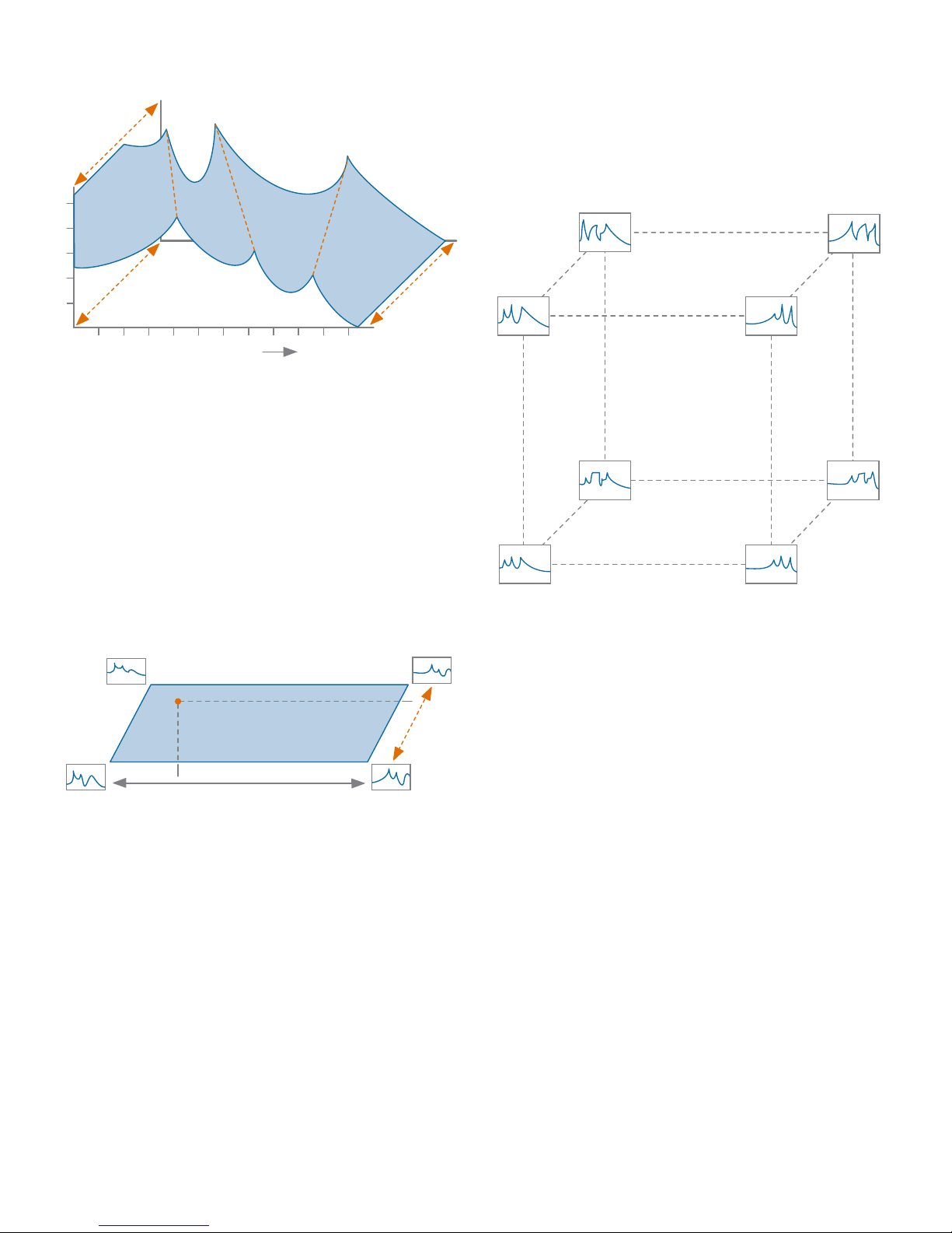
A FREQUENCY RESPONSE: This is the most
basic construct of a Morpheus filter. It is
essentially a single static configuration of
Morpheus’s 14 poles and zeros. For example,
a frequency response might be configured as
six independent bands of parametric EQ and
a low pass section, as in Figure 1, above.
Even this basic building block is capable
of creating filtering and resonant spaces
of enormous complexity. But the real
power comes from the ability to interpolate
between multiple Frequency Responses.
A CUBE: A Cube provides the structure we
need to control the interpolation between
multiple Frequency Responses.
Let’s start with a simple example (actually
simpler than any of the actual Cubes). Let’s
imagine two dierent Frequency Responses
and a single morph parameter to interpolate
between them.
IN OUT
FC QFC BW GAIN FC BW GAIN FC BW GAIN FC BW GAIN FC BW GAIN FC BW GAIN
1 Low Pass
Section 6 Parametric Equalizer Sections
FIGURE 1: A FREQUENCY RESPONSE
MORPH
FIGURE 2: A SIMPLE MORPH

| 7
By varying that single CV-controllable param-
eter, you’re actually interpolating between 20
dierent frequency, bandwidth, resonance,
and gain parameters simultaneously. We can
visualize the result above, in Figure 3.
The next step would be to add another
pair of Frequency Responses and control
them with two parameters. That would look
something like this:
Finally, by adding four more Frequency
Responses, we have a full 3D Morpheus
Cube, now controlled by three parameters,
Frequency, Morph, and Transform.
FIGURE 3:
VARYING A SINGLE CV-CONTROLLABLE PARAMETER
FREQUENCY
AMPLITUDE
MORPH
MORPH
Filter A
Filter B
FREQUENCY
MORPH
FIGURE 4: ADDING A PAIR OF FREQUENCY RESPONSES
In this case, the two parameters (Frequency
and Morph) define a point on a virtual plane
that specifies the interpolation between the
four Frequency Responses. In Morpheus,
configurations of this type are identified with
a “.4” at the end of their Cube name.
In this case, you will be interpolating between
all 8 component Frequency Responses,
controlled by the position of the single
interpolation point within the virtual 3D
space. For ease of visualization, this is
displayed (along with the resulting output
frequency response) on Morpheus’s graphic
display.
A MORPHEUS FILTER: Finally, at the top
level of our hierarchy is the fully-configured
Morpheus Filter. This consists of one of the
289 Cubes and the various parameters set in
the Edit Filter Menu, described in Chapter 8.
FIGURE 5:
3D MORPHEUS CUBES ARE CONSTRUCTED OF 8
DIFFERENT COMPLEX FILTERS
FREQUENCY
TRANSFORM
TRANSFORM
TRANSFORM
TRANSFORM
FREQUENCY
FREQUENCY
MORPH
MORPH
MORPH
MORPH
FREQUENCY

8 |
A Few Words about Distortion
As described in Chapter 8, Morpheus is
capable of producing a wide variety of
unusual and distinctive types of distortion
(depending on the character of individual
cubes and the nature of the signals being
processed). This is separate from the usually
unwanted distortion produced by overdriving
the input or by too high a gain through the
filter.
All of the Morpheus Filters that are based
on “.4” Cubes have by default the Transform
control knob and CV input set to control
distortion (since with only 4 Frequency
Responses, there is no Transform axis to
control anyway). However, even for the
full 3D Cubes, you have the option of
programming the Transform control and CV
to control distortion, in which case the the
actual Transform value is set as a static value
by the Transform CV Oset parameter in the
Edit Filter Menu. Again, see Chapter 8 for
details.
In the following sections, we’ll look at each of
Morpheus’s functions in turn.

| 9
Chapter 10: Utilities
This chapter describes various utility
functions, including loading updated
firmware, boot software, or new filter
cubes, saving and reloading backups of all
your filters and sequences, calibrating your
Morpheus, and more.
Chapter 11: Factory Cubes
This chapter describes each of Morpheus’s
289 Cubes. To help get you up and running
quickly, we’ve provided preconfigured filters
for each of the Cubes.
Chapter 12: Specifications
Yup, specifications.
Chapter 13: From Dave’s Lab
Dave describes our unique approach to
circuit protection.
Chapter 14: Acknowledgements
Thanks to the talented folks who contributed
in one way or another to the development of
Morpheus.
4. How to Use This Manual
While, from a processing point of view,
Morpheus is insanely complex, from a
usability point of view, it’s actually pretty
straightforward. Basically, pick a filter and
modulate it to within an inch of its life.
Beyond that, there’s creating your own
custom filters using the Edit Filter menu,
stringing filters together in series using
the Filter Sequencer, and managing the
housekeeping functions in the Utilities Menu.
With that in mind, the following chapters
guide you through the above functions in
order.
Chapter 5: Basic Functionality
This chapter introduces you to Morpheus’s
basic functional principles, including basic
operation, inputs and outputs, setting
parameters, and loading and saving filters.
Chapter 6: The Main Display
This chapter describes the elements of
Morpheus’s main operational display.
Chapter 7: Managing Filters
This chapter describes saving and loading
your Morpheus filters.
Chapter 8: Editing Filters
This chapter describes editing the various
parameters that define a Morpheus filter.
Chapter 9: Filter Sequencer
This chapter covers the functionality of
the Filter Sequencer, which allows you to
program sequences of filters and navigate
through the sequences with the encoder
or under the control of triggers from other
modules in your system.

10 |
5. Basic Functionality
IMPORTANT: While the left and right
channels are completely independent,
they are both processed by the same filter
(although individual Gain and Distortion
parameters can be selected for each channel).
With that limitation, you can, should you desire,
choose to input completely dierent audio into
the two channels.
Freq CV
This is a control voltage
input that is modified by its
associated attenuverter and
then summed with the values
of the Frequency knob and
the Full Level CV input to
produce the final Frequency
control value.
Before we jump into individual functions, let’s
take a look at Morpheus’s basic organization.
Power Up
When power is applied to the module for
the first time, it begins with Filter 001 as the
Current Filter and the Filter Sequencer OFF.
On subsequent power ups, the Filter and
Sequence that were current at power o are
restored.
Filters
Filters can be selected and loaded using
the Data Encoder as described in Chapter
7or by the Filter Sequencer as described in
Chapter 9.
Custom filters can be created and existing
filters can be edited using the Edit Filter
function. Custom and edited filters can be
saved using the Save Filter function.
Inputs
Audio In Left/Right
Here’s where you
input the audio to
be processed by
Morpheus. These are
true stereo inputs, as the channels’ separation
is preserved through the processing chain to
the outputs.
The Inputs expect a signal level up to 20Vp-p.
Morpheus is DC coupled throughout, so,
with most cubes, you can use it to process
CVs as well as audio.
Full Level
This is an unattenuated CV input
that is summed with the values
of the Frequency knob and the
Freq CV input to produce the final Frequency
control value.
Morph CV
This is a control voltage
input that is modified by its
associated attenuverter and
then summed with the value
of the Morph knob to produce
the final Morph control value.

| 11
Trans CV
This is a control voltage
input that is modified by its
associated attenuverter and
then summed with the value
of the Transform knob to
produce the final Transform,
or optionally, the final
Distortion control value.
NOTE: The function of this CV input (along
with the Transform knob) for each filter
is set in the Edit Filter Menu. If Transform
Controls Distortion is selected for a particular
filter, then Transform is set to a static value
and the knob and CV controls the amount of
distortion produced by the current filter.
Sequencer Dec, Inc, and Reset
Depending on the Filter Sequencer state,
rising edges at these inputs control the
loading of a sequence’s programmed filters
or navigation commands. These inputs
accept digital signals with a threshold voltage
of 1.65V. See Chapter 9 for details.
Outputs
Audio Out Left/
Right
Here’s where the
processed sound
comes out.
Depending on the input levels, the settings of
the various parameters, and the function of
the selected filter, the outputs provide signal
levels of up to 20Vp-p without clipping.
Controls
Data Encoder
The Encoder is used to
select and load Filters
and Sequences as well as
set the value of various
parameters.
The Encoder includes an
integrated pushbutton that is typically used to
load the currently selected Filter or Sequence
or to enter a currently selected parameter
value (see individual parameters for details).
Frequency, Morph, and Transform Knobs
Each of these knobs lets you manually set
a control voltage for its respective axis.
The selected values are summed with their
respective CV inputs to provide the final value
for its axis.
Their range, as indicated on the panel, is from
-5V to +5V. If no oset is set for an axis, its
knob can potentially place the interpolation
point at any location on the axis.
NOTE: A knob’s actual range of placement
will be modified by any programmed
oset of its axis as well as any current control
voltage.
Adjustment of these knobs (as well as any
CVs present) is indicated in real time on the
display by both the graphical CV indicators
and the position of the interpolation point in
the 3D Cube graphic.

12 |
Frequency, Morph, and Transform
Attenuverters
These controls modify any CVs present at
their respective inputs.
When an attenuverter knob is set to its “0”
position, no control voltage at its input is
passed to its associated axis.
As the knob is turned clockwise from 0, the
amplitude of the control voltage increases
until, at maximum clockwise rotation, the full
amplitude of the signal at the input is passed
through.
As the knob is turned counter-clockwise from
0, the signal at the CV Input is inverted (e.g.,
a CV of +2.5V becomes -2.5V). The farther
counterclockwise the knob is turned, the less
the attenuation of the inverted signal, until, at
maximum counter-clockwise rotation, the full
amplitude of the inverse of the signal at the
input is passed through.
Edit Filter/Utilities Button
Pressing this button
gives you access to the
parameters that allow you to
create your own custom filters. Details are in
Chapter 8.
Pressing and holding this button brings up
the Utilities Menu, where you will have
access to Morpheus’s various housekeeping
and maintenance functions. See Chapter 10
for details.
Save Filter Button
Pressing this button allows
you to save new custom filters
or filter edits. Details are in
Chapter 7.
Load Sequence Button
Pressing this button allows you
to select a previously saved
Filter Sequence or to turn the
sequencer on or o. Details are
in Chapter 9.
Program Sequence Button
Pressing this button allows you
to program or edit the steps of
a Filter Sequence. Details are in
Chapter 9.
Save Sequence Button
Pressing this button allows
you to save new sequences or
sequence edits. Details are in
Chapter 9.
Setting Parameters
Apart from the axis CVs set by the front
panel knobs, parameters are set by accessing
the appropriate menu (Edit Filter, Program
Sequence, or Utilities), using the encoder
to select the desired parameter, pressing the
encoder switch to display the parameter’s
current value, using the Encoder to set the
desired value, and then pressing the encoder
switch again to accept the new value.
IMPORTANT NOTE: Whenever there are
any unsaved parameter changes in a filter
or sequence, a red warning (Ffor Filter and
Sfor Sequence) will appear in main display.
If you select a new filter or sequence before
saving them, the changes will be lost.

| 13
6. Main Display
meter extend into the red, you will need to
lower the level of the input signal before
it reaches the filter, by either adjusting the
the level at the signal source or patching it
through an attenuator, VCA, or mixer.
>The middle horizontal bar indicates the
amount of distortion that results from the
distortion settings in the Edit Filter menu.
Red indicates distortion. See Chapter 8 for
details.
>The bottom horizontal bar indicates the
output level through the filter. If you are
seeing this gain meter extend into the red,
you may wish to adjust the Left or Right
Gain settings in the Edit Filter menu to
reduce or eliminate clipping distortion.
See Chapter 8 for details.
The number and name of the currently
loaded filter.
The number and name of the currently
loaded sequence. If the Sequencer has been
turned o, the display, rather predictably, is
“Sequencer O.”
Three horizontal graphical indicators of the
real-time values of the Frequency (F), Morph
(M), and Transform or Distortion (T or D)
inputs to the filter. If a filter is set to control
the Transform axis, The bottom indicator
is labeled “T.” If a filter is set to Transform
Controls Distortion, the indicator is labeled
“D.”
NOTE: The graphic indicators display the
values that are the sum of the manual
settings of the Frequency, Morph, and
Transform knobs and any CVs appearing at
their associated inputs.
ANOTHER NOTE: These graphical CV
indicators always show the cumulative
CVs before any scaling. The 3D Cube
Graphic will show the resulting position of the
interpolation point after all scaling.
Morpheus’s main display provides a variety of
information that gives you a comprehensive
view of what’s happening in the module.
Additionally, there are dedicated displays for
loading and saving filters and sequences,
programming and editing filters and
sequences, and executing utility functions.
In this
chapter, we’ll
describe the
main display.
The rest will
be described
in their own
chapters.
IMPORTANT: OLED displays (which is
what the Morpheus display is) have long
lifetimes under normal use, but if you leave
your system on 24/7 (or just want to ensure
the longest possible life for your display),
Morpheus provides the ability to adjust the
brightness of the display (which is also useful
for optimizing it for the ambient lighting level
of your work environment) and, optionally,
to set a time after which the display enters a
screensaver mode. Both of these can help
extend the life of your display. They are set in
the Utilities menu. Details for setting them will
be found in Chapter 10.
The main display provides the following:
The left and right VU and Distortion Meters.
For each of the two audio channels:
>The top horizontal bar indicates the
channel’s input level. As the level increases
towards the right, the color of the bar
transitions from green to yellow to red,
so you can see at a glance how close to
clipping the signal is. If you are seeing this

14 |
A Cube Graphic that illustrates the 3D
parameter space of the currently selected
filter cube. A colored cross within the cube
indicates the real-time position of the
interpolation point as defined by the values of
the three individual parameter axes.
A Sequencer
Status
indicator
which
displays
the current
sequence
step number
(if the step contains a filter) or an indication
that the sequence is in a Halt (-H-) or Pause
(-P-) state. Anytime that Morpheus receives
a rising edge at the Sequencer Dec, Inc,
or Reset inputs, the display briefly flashes a
yellow indicator showing which input was
activated.
The current fade time scale factor. This
only appears if the Sequencer is On, and
the sequence has advanced to a step that
contains a Fade Time Scale command.
NOTE: If Sequence O has been selected,
the sequence status displays described
above are blank.
Red indicators that light when the current
filter (F) and/or the current sequence (S)
have unsaved changes.
A real-time animated plot of the current
frequency response of the filter. The
horizontal axis is frequency, with lines every
octave starting at 20Hz. The vertical axis
is amplitude, with lines every 10dB from
-30dB to +30dB.

| 15
7. Managing Filters
Loading Filters
When
the Filter
Sequencer is
O, turning
the encoder
will bring
up the Load
Filter box
and scroll
through all
existing filters.
When you
see the one
you want, click the encoder’s switch. The
selected filter will be loaded, respecting the
Exit Fade Time of the previously loaded filter
and the Enter Fade Time of the the newly
selected filter.
If you change your mind before clicking,
scroll back to the currently loaded filter. You’ll
see the Load Filter box disappear.
If you press and hold the encoder switch and
then turn the encoder, each filter will load
immediately as it appears in the Load Filter
box (still respecting the fade out and fade in
times).
When
the Filter
Sequencer is
On, turning
the encoder
will only
display and
select filters in
the currently
loaded
sequence.
The encoder
will skip over
Sequence commands (Pause, Halt, Bumper,
etc) with no eect.
A TIP: This is not only useful for manually
controlling Filter Sequences, but also lets
you use the sequencer to create sub-sets of
filters for easy access in specific situations.
For example, if you’re participating in a live
performance with four dierent pieces, you
can create a separate sequence for each of the
pieces and program each one with only the
filters you use in that piece. That way, during
each piece, you’ll have quick access to the
filters you’ll need, without having to scroll past
lots of filters that you don’t need.
NOTE: As shipped from the factory,
Morpheus contains a series of sequences
that subdivide the filters by basic function.
Loading one of those sequences allows you to
select among only that filter type.
Saving Filters
Press the
Save Filter
button to
bring up the
Save Filter
display. The
current filter
is initially
displayed.
Selecting a
Location
When first
entering this screen, the encoder controls
the Filter Number field. Scroll through the
numbers to select a destination location (or
don’t scroll to resave to the current filter’s
existing location). Note that this scrolling
does include --empty-- filter locations. At
the top of the scrolling list is a special item,
**ERASE**.

16 |
Saving Without Changing the Name
To save the current filter to the selected
location without changing the location’s
existing name, either press the encoder for 2
seconds, or press the Save Filter button for 2
seconds. The display briefly displays “Saving
in 2 Seconds…” and then (after 2 seconds)
displays “Save Completed” and exits the Save
Filter screen.
If you release the button before 2 seconds
have elapsed, the display briefly shows “Save
canceled” and exits the screen without
executing the save operation.
NOTE: The Save Filter operation can also
be exited at any time without saving by
pressing any other function buttons.
Changing the Filter Name
To change the name of the selected target
location, press the encoder. A cursor will
highlight the first character in the Name field.
(If the selected location was --empty--, the
Name field will change to the name of the
current filter.)
The name is changed using the encoder as
follows:
1. After a highlighted character has been
selected using the encoder, press the
encoder to select that character for
changes.
2. Rotate the encoder to select the new
character.
3. Press the encoder to choose the character
and return the encoder to character
location selection operation.
4. Repeat as necessary.
Saving After a Name Change
To save the renamed filter to the selected
location, either long press the encoder, or
long press the Save Filter button. This can be
done while either in the character location
selection or character changing operation
for the encoder. The display briefly displays
“Saving in 2 Seconds…” and then (after 2
seconds) displays “Save Completed” and
exits the Save Filter screen. If you release the
button before 2 seconds have elapsed, the
display briefly shows “Save canceled” and
exits the screen without executing the save
operation.
Erasing the Current Filter
To erase a
filter, press
Save Filter
and then
scroll to the
beginning of
the menu to
display ###
**ERASE**
(where ###
is the filter
number of
the current
filter which will be erased). While **ERASE**
is displayed, either long press the Encoder, or
long press the Save Filter button. The display
will briefly display Erasing Filter and then exit
the screen. If you release the button while
Erasing Filter is displayed, the display briefly
shows Erase canceled and exits the screen
without executing the erase operation.
NOTE: Erasing a filter that is a member of
a Sequence will change the name of that
filter to “--erased--” in the sequence step list
and will replace it with a filter with Null Filter
values.
ANOTHER NOTE: If you, for some bizarre
reason, erase all of the filters in your
module, the next time the module boots up,
the module will contain Filter 001 named
“--erased--” and set to to Null Filter values.

| 17
8. Editing Filters
The Edit
Filter menu
is where you
can create
your own
custom filters
by selecting
from among
Morpheus’s
289 Cubes
and setting
your
desired filter
parameters.
To access
the Edit Filter
menu, press
the Edit
button.
Here are the available parameters:
Select Cube
If you are
creating a
new filter
from scratch,
here is where
you will select
which of
Morpheus’s
289 Cubes
the filter will
use. If you
are only editing the parameters of an existing
filter (gains, osets, etc.), you’ll typically leave
this alone.
NOTE: A special case is Cube 000, the
Null Cube. The Null Cube provides no
processing, so you can think of it as a bypass
of sorts. One reason to program a filter with
the Null Cube is to use it in Filter Sequences
for any steps where you want your audio to
temporarily pass though unfiltered.
Frequency,
Morph, and
Transform
CV Osets
The
Frequency,
Morph, and
Transform
CV Osets
let you
define the
interpolation
point on each respective axis that results
from a cumulative CV of 0V (i.e., manual
knob + CV input(s)) for that axis.
Their range is from -5.0V to +5.0V. The
default value for all axes is 0.0V.
To set parameters:
1. Turn the encoder to scroll through the
available parameter list.
2. Click the encoder to choose the desired
parameter.
3. Turn the encoder to set your desired
value.
4. Click the encoder to return the parameter
list.
The menu is dismissed by pressing the Edit
Filter button again.

18 |
THE DETAILS: With a CV Oset of 0.0V (i.e.,
no oset), a cumulative CV of 0V results in
the interpolation point being in the exact
center of its axis. In this case, a CV of +5.0V
will place the point at one extreme end of the
axis, while a CV of -5.0V will place it at the
opposite extreme.
But if, for example, you set an oset of +2.0V,
when you have a CV of 0V, the interpolation
point will be 2/5 of the way from the center
of the axis towards one end of the axis. In this
case, it only takes a CV of +3.0V to move the
point to the extreme end.
A CV of -2.0V will place the point exactly in
the center of the axis, and it will take -7.0V to
move the point to the opposite end of the
axis.
NOTE: With no CV Oset, the Frequency,
Morph, and Transform knobs can place
the interpolation points for their axes anywhere
within the 3D Cube space without the need
for any additional CV. However, when any
CV Oset is programmed, the knobs can no
longer cover the entire range by themselves
(unless you increase the CV gain). In that case,
additional CV input is required to cover the
entire range.
ANOTHER NOTE: The interpolation point
can never extend beyond the edge of
the 3D Cube space. In the example above,
once a CV of 3.0V has moved the point to the
extreme end of its axis, any additional CV over
3.0V will have no eect.
YET ANOTHER NOTE: When Transform
Controls Distortion is selected for a
particular filter, The Transform CV Oset
parameter defines the static position of the
Transform axis.
Frequency,
Morph, and
Transform/
Distortion
CV Gains
The
Frequency,
Morph, and
Transform/
Distortion
Gain settings
let you scale
the cumulative CV (i.e., manual knob + CV
input(s)) for each axis.
Their range is from -9.9x to +9.9x. Hence,
1V can span from 1% to 100% of an axis.
The default value for all axes is 1.0x (i.e., no
scaling).
Values greater than one result in an increase
of the cumulative CV.
Values between .99x and .01x result in a
decrease of the cumulative CV.
Values of less than 0 both scale and invert
the CV. For example, with a CV Gain value
of -2.0X and a cumulative CV of +1.5V, the
resulting CV would be -3.0V.
NOTE: When Transform Controls
Distortion is ON, the Transform CV Gain
parameter changes it name to Distortion CV
Gain.
IMPORTANT NOTE: The graphical CV
indicators always show the cumulative
CVs before any scaling. The 3D Cube
graphic will show the resulting position of the
interpolation point after all scaling.

| 19
Enter Fade
Time and
Exit Fade
Time
When
transitioning
from one filter
to another,
either
manually by
using the
encoder or
via the Filter Sequencer, you can program
independent Enter Fade Times and Exit Fade
Times for each filter. The total transition time
for any filter change will be the sum of the
Exit Fade Time for the outgoing filter plus the
Enter Fade Time for the new filter.
NOTE: The Fade Times programmed here
can be scaled up or down (i.e., to be faster
or slower) when a filter appears in the Filter
Sequencer. See Chapter 9 for details.
Left and
Right Gain
These
parameters
let you set
the gain
from input
to output of
each filter
channel (Left
or Right).
The resulting
output gains are displayed on their respective
channel output meters on the main display.
If you see the output meters in the red (and
you don’t like the resulting sound), you can
reduce the gain here to bring the levels down
below clipping.
Their range is -40dB to +40db in 1dB
intervals. The default value for both channels
is 0dB.
NOTE: These parameters only aect the
gain through the filter. If you are seeing
the input gain meters extend into the red, you
will need to lower the level of the input signal
before it reaches the filter, by either adjusting
the level at the signal source or patching it
through an attenuator, VCA, or mixer.
Left and
Right
Distortion
Morpheus is
capable of
producing a
wide variety
of unusual
and distinctive
types of
distortion
(depending
on the character of individual cubes and the
nature of the signals being processed). These
parameters set the amount of internal filter
distortion for each channel (Left or Right).
The range is from -30dB to +70dB.
The resulting amounts of distortion for each
channel are displayed on their respective
distortion meters on the main display (red
indicates distortion). However, the most
productive way of adjusting these parameters
is by ear, i.e., just vary the values until you get
the sound you want.
NOTE: If Transform Controls Distortion
is OFF, these parameters set the static
amounts of filter distortion. If Transform
Controls Distortion is ON, these controls set
the amounts of distortion with no CVs present.
CVs from the Transform Knob or Transform
CV Input will further modify the distortion
amount from that initial setting.

20 |
ANOTHER NOTE: It’s important to
remember that the filter distortion set by
these parameters is intended to be a creative
tool and is separate from the distortion that
results from a too hot input to the filter or the
distortion resulting from too high a setting of
the Left and Right Gain parameters described
above. Those are the kinds of distortion you
typically don’t want (although maybe you do —
it’s always your choice).
YET ANOTHER NOTE: Changing the Left
and Right Gain will not aect the amount
of internal distortion, only the output level.
Transform
Controls
Distortion
The
Transform
Controls
Distortion
function lets
you choose
whether the
Transform
control, CV
input, and Gain setting aect the Transform
axis interpolation point or the amount of filter
distortion.
When this parameter is OFF:
>The Transform Knob and the Transform
CV Input, in combination with the
Transform Gain and CV Oset, control
the interpolation point on the Transform
Axis.
>The Left and Right Distortion parameters
set the static amount of distortion for their
respective channels.
When this parameter is ON:
>The Left and Right Distortion parameters
set the initial amount of distortion for their
respective channels.
>The Transform Knob and the Transform
CV Input, in combination with the
Distortion Gain parameter provide real-
time control of the amount of distortion.
>The Transform CV Oset sets the static
position of the interpolation point on the
Transform Axis.
NOTE: When Transform Controls
Distortion is ON, the Transform CV Gain
parameter in the Edit Filter menu changes its
name to Distortion CV Gain.
ANOTHER NOTE: By default, all factory
filters that end in “.4” are set to Transform
Controls Distortion. Since these filters consist
of only 4 frequency configurations, controlling
the Transform axis generally has a less
interesting eect.
Table of contents
Other Rossum Synthesizer manuals