RWD R419 User manual

R419 Intelligent Animal
Ventilator
User Manual A

© 2020 Shenzhen RWD Life Science Co., Ltd, All rights reserved.
Intellectual Property Right
The intellectual property rights of this product and its instruction manual belong to RWD Life
Science Co., Ltd (hereinafter referred to as the RWD), including, but not limited to patent,
trademark, copyright etc.
RWD reserves final interpretation right of this instruction manual.
RWD have the right to use the instruction as confidential information. Any individual and/or
organization shall not disclose the instruction of all or part of the information by any means
without RWD’s written permission. Nor shall any other person or organization be allowed to
obtain all or part of the information of this instruction manual by any means.
No individual and/or organization shall publish, modify, reproduce, issue, rental, adapted, and
translated into other languages without RWD’s writen permission.
is RWD’s registered trademark or mark, these trademarks and the related security
mark belong to RWD’s intangible property. The use of non RWD’s trademark or mark in this
instruction manual are only for editing purposes, without other purposes, the rights belong to their
respective rights owners.
Statement
RWD reserves the right to modify the content of this manual without prior notice.
RWD reserves the right to change the technology without prior notice.
RWD reserves the right to modify the product specifications without prior notice.
RWD does not guarantee the information in any forms, including (but not limited to) the
responsibility of proposing the implied merchantability and suitability for a specific purpose.
RWD in only the following conditions is considered to be responsible for the safety, reliability and
performance of the instruments, i.e.:
Assembly operation, expansion, adjustment, improvements and repairs carried out by RWD
authorized personnel;
Relevant electrical equipment in line with national standards;
The instrument is operated according to the instruction manual.
RWD is not responsible for the products’ safety, reliability or operation status in the following
conditions:
Components are disassembled, stretched or debugged;
Non RWD authorized personnel repairs or alterations to the instruments;
Product may not in accordance with the manual.

Contents
1-INTRODUCTION ..............................................................................................................1
1.1 OVERVIEW...........................................................................................................................1
1.2 SAFETY ...............................................................................................................................1
1.3 PRODUCT FEATURES............................................................................................................1
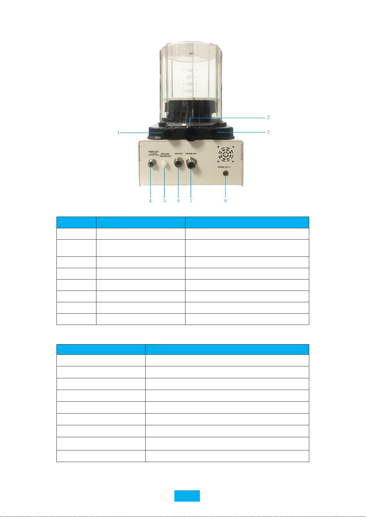
1.4 INTRODUCTION OF DEVICE’S MAIN COMPONENTS ................................................................2
1.5 SPECIFICATION ....................................................................................................................3
2-SYSTEM SAFETY .............................................................................................................4
2.1 SAFETY INSTRUCTIONS........................................................................................................4
2.2 CAUTIONS ...........................................................................................................................4
2.3 SAFETY INSTRUCTIONS........................................................................................................5
2.4 WARRANTY.........................................................................................................................5
3-UNPACKING AND ASSEMBLY ......................................................................................7
3.1 NOTICE FOR USE .................................................................................................................7
3.2 INSTALLATION .....................................................................................................................7
4-OPERATING INSTRUCTION .......................................................................................10
4.1 POWER-ON SELF-CALIBRATION/TEST ................................................................................10
4.2 LEAKAGE DETECTING .......................................................................................................11
4.3 MODE SETTING .................................................................................................................11
4.4 WEIGHT SETTING ..............................................................................................................12
4.5 SETTING OF BREATHING PARAMETERS ..............................................................................13
4.6 ADD, CALL, DELETE AND ADJUST PARAMETERS...............................................................14
4.6.1 Add Parameters.............................................................................................................14
4.6.2 Call Parameters ............................................................................................................14
4.6.3 Delete Parameters.........................................................................................................15
4.6.4 Adjust Parameters.........................................................................................................15
4.7 SYSTEM SETTING ..............................................................................................................16
4.7.1 Brightness Control ........................................................................................................16
4.7.2 Chinese-English shift ....................................................................................................16
4.7.3 Calibration ....................................................................................................................16
4.8 ALARM INFORMATION AND PROCESSING ...........................................................................17
4.8.1 Alarm Prompt of High Airway Pressure .......................................................................17
4.8.2 Alarm Prompt of “High / Low Gas Source Pressure” ..................................................18
4.8.3 Alarm Prompt of “Low Flow” ....................................................................................19
4.8.4 Alarm Prompt of Breathing Tubes Blocked...................................................................19
4.8.5 Alarm prompt of is Low Battery....................................................................................20
4.8.6 Alarm Prompt of Over-temperature ..............................................................................20
4.8.7 Alarm prompts for Circuit abnormality ........................................................................20
4.8.8 Message Prompt of “Inspiration hold” ........................................................................20
5-CLEANING AND MAINTENANCE..............................................................................22
5.1 PRODUCT CLEANING .........................................................................................................22

5.2 BATTERY MAINTENANCE...................................................................................................22
5.2.1 Battery Performance Maintenance ...............................................................................22
5.2.2. Check battery performance..........................................................................................22
5.3 RECYCLING BATTERIES .....................................................................................................22
6-TROUBLESHOOTING...................................................................................................24
7-RETURN TO FACTORY FOR REPAIR .......................................................................25
8-AFTER-SALE SERVICE ................................................................................................26
9-TECHNICAL PARAMETERS........................................................................................27

1
1-Introduction
1.1 Overview
Thank you first for choosing the R419 Intelligent Animal Ventilator produced by the RWD
Life Science Co., Ltd (hereinafter referred to as the RWD)!
For better use of this product, please read the supplied instructions carefully before the initial
installation and use of this product.
RWD Life Science Co., Ltd. is endeavored to improve the product function and service quality.
RWD reserves the right to change or alter the contents of user manual without prior notice.
If you would like the latest product information, you are welcome to call us or visit our website
(http://www.rwdstco.com/). If you find any discrepancy between the instruments and this manual
during the practical use of our product, or if you have any questions or suggestions, you are
welcome to contact us.
1.2 Safety
In order to avoid the harm to the experimental animal or operator and the damages to the
ventilator, please refer to Chapter “2-System Safety”.
If you have any questions or suggestions related to safety, please contact our company for
after-sales service support.
1.3 Product Features
The appearance is simple, light and elegantly colored, compact layout, and an overall
small size. It can be equipped with a respiratory anesthesia machine bracket, which is
flexible and convenient to operate;
Three modes are available: Volume Control Mode (VCV), Pressure Control Mode
(PIP-CV), and Apnea Mode (APNEA);
Equipped with two different sized bellows (300 ml and 1500 ml) suitable for animals
weighing less than 100kg;
Display specifications: 5-inch LCD color display is simple, intuitive, and easy to
operate, with real-time readings of monitored data;
Intelligent input: imports the commonly used animal breathing parameters into the
database, input the weight, and it automatically outputs the recommended breathing
parameter values;
Breathing parameter storage and recall;
Real-time display of breathing-related curve parameters, which is intuitive and
This device is only used for clinical or scientific research
of animals and is not allowed to be used on humans!
The Intelligent Animal Ventilator should only be
operated by trained personel.

2
visual;
Auditory alarm, with text message prompts, improving human-machine interaction, and
reducing human error;
It is powered by an internal rechargeable battery and will run for more than 4 hours
while unplugged.
1.4 Introduction of device’s main components
Fig 1
No.
Parts
Description
1
Bellows cover
To isolate fresh gas from driving gas
2
Folded bag
Inputs fresh oxygen and anesthetic gas into the lungs of the
animal
3
Base
To connect device and bellows
4
Display screen
To display device operation information and set parameters
5
Battery indicator
When powered by the battery, this indicator will be on.
6
External power
indicator
After the equipment is connected to an external power
source, this indicator will be on.
7
INSP.HOLD Button
Refers to inspiration hold button. An inspiration will be
held while this button is pressed.
8
Power switch button
Press button and hold for 1 second to start the equipment.
When you hear the equipment prompt tone, the equipment
is turned on, and will enter the self-calibration interface.
Pressing the button for 3 seconds will off the equipment.

3
Fig 2
No.
Components
Description
1
Fresh gas port
To anaesthesia machine
2
anaesthetic wastes exhaust
port
To gas filtration tank
3
17mm port
To the port of the driving gas
4
Port of gas source
Oxygen source (or air)
5
Port of pressure sensor
To 22mm port
6
Air outlet
Discharge waste gas of the driving gas
7
Port of the driving gas
To 17mm port
8
Power adapter interface
Power input port
1.5 Specification
Item
Specification
Dimension
253mm×224mm×112mm
Weight
3.22kg
Respiratory rate
2~60 bpm
I:E
1:1.0~1:4.0
Tidal volume
20~1500ml
Peak inspiratory pressure
5~35 cmH2O
Trigger pressure
-9.0 ~ -1.0 cmH2O
Patient weight range
≤100.0kg
Touch screen
5 inch, 800 × 480

4
2-System Safety
2.1 Safety Instructions
For safety, please pay attention to the following items:
Please read the user’s manual carefully.
Operating conditions of R419 Smart Veterinary Ventilator:
Temperature: 0℃~ +40℃, humidity:15%~95% (non-
condensing),atmospheric pressure: 70kPa ~ 110kPa
Storage conditions of R419 Smart Veterinary Ventilator:
Temperature: -20℃~ +45℃, relative humidity : ≤95%, atmospheric pressure:
70kPa ~ 110kPa
Warning:
When high pressure oxygen meets combustible materials (lubricating grease, motor oil,
alcohol, etc.), it may cause an explosion:
Keep the equipment and all connections absolutely free of oil and grease.
It is strictly forbidden to smoke near the ventilator and/or ignite an open flame.
When installing and replacing the oxygen cylinder, use your hand as much as possible
to tighten all the connections on the oxygen cylinder and pressure relief valve. If you
need to use tools, do not use excessive force, it may cause damage to the threads and
sealing materials and may result in gas leakage.
Take measures to prevent the oxygen cylinder from tipping over. If the oxygen
cylinder falls over, the pressure relief valve may be damaged and cause an explosion.
Important:
Always open the pressure relief valve on the oxygen cylinder slowly to prevent
the surge of pressure from impacting the valve fittings inside the ventilator.
Always check the pressure of the oxygen cylinder. Do not completely exhaust the
oxygen in it, humidity in the surrounding air may invade it and cause parts to rust.
Attention:
Animals and the ventilator must be continuously observed during use.
The breathing circuit interconnected with the anesthesia machine needs to be
remain unobstructed and easy to observe. Avoid operations that may result in
covering or affecting their function (e.g. improper location of the animal).
A large number of quality assurance measures have been taken in the
development of the equipment software, and the risk due to software defects is
minimal.
Take measures to protect the rubber components from ultraviolet light and
prolonged direct sunlight, to avoid embrittlement of these parts.
2.2 Cautions
Before operating this equipment, the operator should meticulously read this user’s manual
and fully understand its contents.
Before using this equipment, please carefully check all connectors to ensure adequate

5
gas-tightness and to avoid any leakage.
Equipment malfunctions caused by improper cleaning, maintenance or operation will
be considered the user’s responsibility.
If someone disassembles the equipment’s main body without authorization, RWD shall stop
providing any quality assurance or technical maintenance service to this equipment. If the
user has any technical questions, please contact the authorized person or the RWD for
support.
Risk of electric shock: Laypeople are prohibited from removing the cover or panel of the equipment and
removing the built-in rechargeable battery.
DANGER: The use of flammable or explosive gases as a gas source for the equipment is prohibited.
2.3 Safety Instructions
The use of this equipment is limited to persons with relevant expertise in respiration and
anaesthesia or persons trained by the manufacturer.
Keep the equipment away from water, with good ventilation and relatively consistent air pressure,
temperature and humidity. It should not be exposed to direct sunlight or places with gases or chemicals
that are corrosive, flammable or explosive. During placement or handling of the equipment, operators
should prevent the equipment from being inclined, vibrated or squeezed.. Pay attention to the voltage,
current and frequency of the connected power source, and make sure that the grounding terminal is
normal. Avoid overloading the equipment.
Warning!!!
The R419 Smart Veterinary Ventilator should self-calibrate when started. If self-calibration
cannot be done, it means there may be some kind of circuit breakdown or internal pipe leakage. In
that case the user should turn off the equipment power and make sure the gas source pressure is
between 41-87 psi, the breathing circuit connection is correct, and the flow rate of the anesthesia
machine is appropriate (note that the breathing circuit is connected to the breathing bag at this time,
and the evaporating tank of the anesthesia machine is closed). Then, turn on the equipment for self-
calibration after the folded bag in the bellows of the ventilator rises to the top of the bellows. If
self-calibration fails again, please contact your supplier or the RWD after-sales service department
for further support.
2.4 Warranty
The warranty of this equipment starts from the day it leaves the factory. If the equipment cannot
be used normally due to problems such as materials and/or process defects, the company
undertakes after-sales service such as maintenance and/or part replacement.
Warning!
It is forbidden to use the oxygen flush button on the anesthesia machine
during the inspiration phase of the breathing cycle. It may cause severe lung
rupture in the animal. During the inspiration phase, the drain valve in the control
unit is closed, so the oxygen flow is added to the breathing machine's air supply
flow, and the only direction of the airflow is to the lungs of the experimental
animal.

6
Any damage caused by improper use is not covered by the warranty. If repair or replacement
of parts is required, the cost will be borne by the user.
If the equipment that has been returned for repair has been dismantled without the
authorization of RWD before arriving at RWD, the company does not provide after-sales
service such as warranty, free maintenance or parts replacement.
The warranty statement (including its restrictions) is exclusively issued by RWD and covers
all other warranties.

7
3-Unpacking and Assembly
1) Inspect the packing for any signs of damage that may have occurred during shipping, if
damage has occurred, make a damage claim to the carrier and contact with RWD or
your local dealer immediately.
2) Remove all components from the shipping carton. Save all boxes and packing materials
for future shipments.
3) Check the packing list to ensure all components ordered are included. Ifthere is any
doubt or you need help, contact RWD or your local dealer immediately.
Packing list:
Device body -------------------------------------------------------1
300ml Bellows and bellows cover --------------------------------------1
1500 ml Bellows and bellows cover ----------------------------------- 1
1.2 m Bellows pipe ------------------------------------------------- 1
(For connecting ventilators and gas filter cans)
0.9m Reusable threaded pipe ---------------------------------------- 1
(Used to connect anesthesia machines and ventilators, can be steam sterilized)
Airway pressure connection pipe - Luer-22mm connector ------------------ 1
Rubber booster tube(ID : 15mm) -------------------------------------1
30-22mm Bellows joint ----------------------------------------------1
Power cable----------------------------------------------------------- 1
Power Adapter ------------------------------------------------------ 1
Warranty card -------------------------------------------------------1
User manual ------------------------------------------------------------ 1
Note: If your order contains other gadgets, it may also be packed at the same time. Please refer to the
waybill.
3.1 Notice for Use
Before using this equipment, please make sure to read the user’s manual carefully!
This equipment is designed to perform the functions referred to in this manual. Please use and operate the
equipment according to the relevant instructions in the manual. This equipment should be checked and maintained
periodically to ensure its reliable operation.
It is suggested you stop the use of the equipment and change the parts produced by our company or the
companies authorized by our company, if the following situations occur to any component: Damage to all or part
of the equipment, excessive wear, service life termination caused by contamination or other reasons.
Use of any equipment that has stopped functioning normally should be stopped immediately. The user should
not change the equipment in any form. It is the responsibility of the user if the equipment is not used in accordance
with our company’s user’s manual, or if the user changes or makes unauthorized repairs to the equipment, or if said
changes or repairs results in damages to experimental animals or properties (including the equipment itself).
3.2 Installation
i. Check that the control host (main body) is intact and all interfaces on the rear panel, to
ensure that the air supply port (SUPPLYGAS), the driving gas port (DRIVING GAS),
and the exhaust port (EXHAUST) are not blocked;
ii. Check that the bellows and bellows cover are intact and that there is no debris inside
bellows;
iii. Install the bellows and bellows cover. Make sure the corrugated sheath at the bottom of
the bellows around the mounting ring of the control host, gently holds the outer edge

8
of the bellows disc (top of the bellows), lift it up and down, and repeat several times to
smooth out the ripples on the bellows. Then replace the bellows cover and gently press
and rotate the bellows cover clockwise until it snaps into the bayonet at the base. The
bellows and bellows cover are now installed.
Fig 3
iv. Connect the pipes of the driving gas. Use a rubber boosting tube to connect the 17mm
port of the bellows base to the driving gas port (DRIVING GAS) on the control unit;
Fig 4
v. Install the breathing circuit port. Connect the airway pressure connection pipe (Luer
taper) on the side of the airway pressure connection pipe - Luer -22mm connector to
the port of pressure sensor (PRESSURE TRANSDUCER) of the control unit, tighten
it, and then install the 22mm connector (transparent) onto the 22mm port of the
bellows base;

9
Fig 5
vi. Connect the ventilator to the anesthesia system. Remove the breathing bag from the
anesthesia machine and connect the 22mm port on the bellows base to the breathing
bag interface of the anesthesia machine with a threaded pipe;
Fig 6
vii. Connect the ventilator to the gas recovery system. Connect the 22mm bellows
connector to the 30mm port on the bellows base and connect to the gas filtering tank
using the bellows.
Fig 7
viii. Connect the gas supply system. Use an oxygen tube and a three-way valve to connect
the pressure relief valve of oxygen cylinder (gas output pressure should range from 41
to 87psi) to the air supply port (SUPPLY GAS) on the ventilator. The other outlet of
three-way valve is connected to the air interface of the anesthesia system.

10
4-Operating Instruction
4.1 Power-On self-calibration/test
1) Connect the gas source pipes of the anesthesia machine and the R419 intelligent ventilator,
turn on the gas source switch, adjust the pressure output of the decompression meter to 50
psi (0.344 MPa recommended value), and confirm that the volatilization tank switch of
anesthesia machine is adjusted to “0” position;
2) Connect the breathing circuit according to Section 3.2, open the anesthesia machine
flowmeter, and adjust the flow rate to about 1 L/min. When the folded bag of R419 Smart
Veterinary Ventilator bellows rises to the top of the transparent cover, press and hold the
power switch for 1 second to start the equipment. The equipment will give a click sound and
enter the self-calibration interface. Self-calibration will test the power source voltage,
battery voltage, air source pressure, airway pressure and sensor.
Fig 8
3) After the self-calibration passes, the interface automatically enters the main interface after 3
seconds;
Fig 9

11
After the R419 Smart Veterinary Ventilator enters the main interface, users can set the breathing
parameters such as the inspiration/ expiration ratio and airway pressure upper limit alarm. Press
to enter sub-main interface for setting the system parameters, such as adjusting the brightness
of the LCD screen.
Fig 10
4.2 Leakage Detecting
Operation method:
After connecting the ventilator to anesthesia machine, adjust the flowmeter to 0.3L/min, adjust
the upper pressure limit displayed on the main interface of the ventilator to 30cmH2O,
click to start, after several breathing cycles, the real-time tidal volume(VT)reaches the set
value, then press the HOLD button until the airway pressure value rises or falls slowly. Rising
means the air tightness is good. If it is falling, no more than 3 cmH2O within 10 seconds, the air-
tightness is still considered adequate. If the drop in pressure exceeds these values, there may be a
problem with air leakage or tube circuitry. After having checked that the tube is tightly
connected, and the airway pressure still drops more than 3 cmH2O in less than 10 seconds, then
there is a leak in the ventilator. It is recommended that the user follows the above steps to
regularly check the ventilator, to avoid affecting its operation.
4.3 Mode Setting
Click any mode to enter the parameter editing interface. Click on the parameter editing
interface to select any ventilation mode.

12
Fig 11
Volume Control Mode (VCV): With tidal volume (VT) as the reference standard, the
inspiration process is complete when the volume of gas inhaled by the animal reaches the set tidal
volume;
Pressure Control Mode (PIP-CV): With peak inspiratory pressure (PIP) as the reference
standard, the inspiration process is complete when the gas inhaled by the animal reaches the set
peak inspiration pressure;
Apnea Mode (APNEA): Selecting this mode will allow the animal to spontaneously breath;
when the animal does not breath for a pre-set period of time, the air supply starts immediately,
and delivers the pre-set assisted ventilation. This process will cease when the animal begins to
spontaneously breath again. If the user observes that the animal has begun to spontaneously
breath, and assisted ventilation is no longer necessary, the user can stop the ventilator and end
assisted ventilation.
4.4 Weight Setting
After selecting this mode, enter the animal's weight. The system automatically matches the
recommended parameters in accordance with the entered weight. The adjustment range of the
weight input is 2.0-100.0 kg, and the input step is 0.1kg.

13
Fig 12
4.5 Setting of Breathing Parameters
Users can also enter other parameters according to need:
VT: During ventilation, the inspiratory volume is controlled in real time with reference to
the set tidal volume (VCV). When the tidal volume setting is reached, the inspiration is over. The
adjustment range of tidal volume is 20 ~1500 mL.
Flow: The device ventilation mode is selected as PIP-CV. The intelligent input
automatically matches the flow rate. The user can also adjust the ventilation speed of the flow
control device. The flow adjustment range is 1~85L/min.
Rate: When the breathing rate controls ventilation, the equipment breathes according to the
set breathing rate, and the breathing rate can be adjusted within a range from 2 to 60 bpm.
PIP: The equipment ventilation mode is selected as PIP-CV. Refer to the set PIP to control
the airway pressure in real time during the inspiration. When the peak inspiratory pressure setting
value is reached, the gas supply ends. The PIP adjustment range is 5~35 cmH2O.
I:E: In VCV/APNEA ventilation mode, the equipment controls ventilation according to the
set inspiration/ expiration ratio. The parameter range of the inspiration/ expiration ratio is
1:1.0~1:4.0.
PLIMmax: When ventilation is performed in VCV/APNEA mode, the inspiration volume
during inspiration, is controlled in real time in reference to the set tidal volume. When the tidal
volume pre-set value is reached, the inspiration is complete, and the upper pressure limit is used as
the airway pressure during inspiration for over-pressure protection with real-time monitoring in the
animal VCV mode. When the airway pressure reaches the upper pressure limit, and the inspiration
volume does not reach the set tidal volume, the ventilator sounds an alarm and automatically adjusts
and enters the exhalation state in advance. The upper limit of the maximum pressure is 10~60
cmH2O.
Trig: The trigger pressure adjustment range in VCV/PIP-CV/APNEA mode is -9 ~ -1 cmH2O,
the adjustment step length is 1 cmH2O. Adjusting to 0 will turn off the trigger pressure setting, and
OFF will be displayed. Ventilation is completely controlled by the ventilator; APNEA mode
prohibits the trigger pressure from being off and the parameter cannot be set to 0.
APN.T: ‘Waiting time’ is the time from when a complete spontaneous breath is taken in

14
APNEA mode, to the start of the next inhalation, referring to the time point when the trigger
pressure is reached by the last spontaneous breath. After the set waiting time is reached, the
ventilation control will start, and the waiting time adjustment range is 15~30 seconds.
The real waiting time must be greater than or equal to the set waiting time.
Note: In VCV/APNEA mode, when any one of the three parameters of tidal volume, breathing
rate and/or inspiration/ expiration ratio is set, the system’s total flow range in real time must
be within 1~85L/min, otherwise the system will display a prompt message, and the parameters
will not be available.
4.6 Add, Call, Delete and Adjust Parameters
Fig 13
4.6.1 Add Parameters
1) Click the [New] button to enter the new interface for naming. After naming is complete,
click "OK” to enter the parameter editing interface, or click [Return] to go back to the
parameter list interface;
2) Enter the parameter editing interface, a default intelligent parameter group including a
weight of 20 kg will display. Confirm whether to adjust each parameter according to need.
Click [OK] to enter the parameter list interface. The [Parameters List] has one new name in
the parameter group; click “Return” to enter the parameter list interface. The newly named
parameter is at the back part of the group list in the parameter list interface, but the parameter
value still maintains the default value of 20kg intelligent input; the shading is located on the
new parameter group by default;
3) When the parameter list interface has saved 20 parameter groups, click the [New] button, and
the pop-up prompt "The 20 sets of parameters have been saved, please delete some for new
ones!”,will display, then click the [OK] button to exit the pop-up box.
4.6.2 Call Parameters
1) Click a parameter number in the naming area of the [Parameter List] interface to pre-select
this parameter group, and click the [Select] button to select this parameter group in the
main interface;

15
2) If other parameters are selected when the equipment is in the process of ventilation, the
current breathing cycle will not be forcibly interrupted. The selected procedures are
performed after the current breathing cycle ends;
4.6.3 Delete Parameters
1) Click a parameter number in the naming area of the [Parameter List] interface to pre-select
this parameter group. You can check this parameter group in the parameter display area;
2) Click “Delete” to delete the parameter group, and the prompt box “Are you sure you want
to delete these parameters?” will display. Click [Yes] to delete, and the next parameter
group in line will be moved up into its place, but the shading position will remain
unchanged. After deleting the last parameter group, the check box will move up; click
[No] to return to the [Parameter List] interface;
Fig 14
3) After deleting the last named parameter group in the parameter list interface, the [Delete]
button is disabled;
4) The “Unnamed” parameter group cannot be deleted, it is optional, and the [Delete] button
is disabled;
5) The main interface uses the parameter group ABC, the parameter list interface pre-deletes
the parameter group, and displays the prompt "It is in use and cannot be deleted” Click the
OK button to exit the pop-up box;
Fig 15
4.6.4 Adjust Parameters
1) Parameter list interface: Click the parameter to adjust, confirm the adjustment and return
to the parameter list interface; the parameter will change under the same name;
2) Main interface: Click on the parameter to adjust, confirm the adjustment and return to the
main interface. After the parameter has been adjusted, it will temporarily be stored as
[unnamed]. The previously unnamed cached parameters are replaced with the most
recently adjusted parameters. The parameters named before adjustment and stored in the
[Parameter List] interface will not be affected;

16
3) After adjusting the parameters during ventilation, the newly adjusted parameters will be
executed during the next inspiration phase, and the current breathing cycle will not
forcibly interrupted.
4.7 System Setting
Fig 16
4.7.1 Brightness Control
1) Click & to adjust the backlight brightness.
2) When the device is powered by the internal battery, the current display brightness will be
80% of the set brightness;
3) The brightness of the equipment when switched on will be consistent with the brightness
before the last shutdown;
4.7.2 Chinese-English shift
1) Click 【中文】 to switch the system language to Chinese, or [English] to switch the
system language to English.
4.7.3 Calibration
1)Click to enter the interface as shown in the figure below (Note: be sure to
unplug the threaded pipe shown in Figure 18 before calibration), and click the “Clear”
button on the right side of “Airway Pressure sensor”. (We recommended this to be cleared
monthly)
Table of contents
Popular Fan manuals by other brands

Monte Carlo Fan Company
Monte Carlo Fan Company 5CSM60 Series Owner's guide and installation manual

Modern Forms
Modern Forms Smart Fans XF-SCK installation instructions

Helios
Helios Ecovent Verso KWL EC 45 Installation and operating instructions

NOMA
NOMA Miles instruction manual

nedis
nedis FNFL20CBK30 quick start guide

Modern Forms
Modern Forms F-WCBT-WT installation instructions

Greenheck
Greenheck SBCE Installation, operation and maintenance manual

Mitsubishi Electric
Mitsubishi Electric Lossnay VL-220CZGV-EB instruction manual

Schübeler
Schübeler HST Series Manual of Instruction

Hunter
Hunter Saturn 90053 Parts guide

Mars
Mars Comfort-Aire FB-3630B-MBL Series owner's manual

RS
RS PFN-40B owner's manual