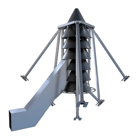
S3 0312FC User manual


Table of Contents
1 Sign-Off Form ....................................................1
2 Introduction ......................................................2
3 General Information .........................................2
4 Safety ................................................................3
4.1 Safety Alert Symbols ................................3
4.2 General Safety..........................................3
4.3 Electrical Safety........................................4
4.4 Operational Safety ...................................5
4.5 Emergency Shutdown Procedure:............5
4.6 Storage .....................................................5
4.7 Preventing Bin Damage............................5
4.8 Maintenance Safety .................................5
4.9 Safety Decals ............................................6
4.10 Decal Installation......................................6
4.11 Decal Maintenance ..................................6
4.12 Decal Replacement ..................................6
4.13 Decal Locations ........................................6
5 General Information .........................................9
5.1 Electrical...................................................9
5.2 Fan Blade..................................................9
6 List of Features..................................................9
6.1 General Features......................................9
6.1.1 In-Line Centrifugal Aeration Fan ..........9
6.1.2 Full Speed Centrifugal Aeration Fan ....9
6.1.3 Low speed Centrifugal Aeration Fan..10
6.1.4 Motor Features..................................10
6.1.5 BIN-SENSE Ready ...............................10
6.1.6 Fans Weights & Motor Data………….11
7 Packing List......................................................16
7.1 In-Line Centrifugal Fans..........................16
7.2 Full Centrifugal Fans…………………………….16
7.3 High/Low Speed Centrifugal Fans ..........16
7.4 Turbo Aeration Fans.Error! Bookmark not
defined.
8 Fan Model Specifications ................................17
8.1 Aeration Fan Model Specifications .. Error!
Bookmark not defined.
8.2 Full Speed Centrifugal Fans ....................18
8.3 In-Line Centrifugal Fans..........................21
8.4 Turbo Fans..............................................22
8.5 Low Speed Centrifugal Fans ...................23
8.6 High Speed Centrifugal Fans …………….24
9 Performance ...................................................25
10 Installation Instructions ..................................26
10.1 Mechanical Check ..................................26
10.2 Foundation as Required For Fan ............26
10.3
Installation of the Fan
...........................27
10.3.1 Fastening the Aeration Fan to a
Flanged Adapter..............................................27
10.3.2 In-Line Centrifugal & Turbo Fan
Installation ......................................................27
10.3.3 Low Speed Fan Installation............27
10.3.4 Full Speed Centrifugal Fan
Installation ......................................................28
10.4 Electrical Installation ..............................29
10.4.1 General Instructions ......................29
10.4.2 Electrical Service Installation.........29
10.4.3 Motor Safety..................................29
10.4.4 Motor Enclosure............................29
10.4.5 Electrical Connection at the Fan....29
10.4.6 Wiring ............................................30
10.4.7 Installation of Accessories .............30
11 Operating Instructions ....................................31
11.1 Before Starting the Fan ..........................31
11.2 Starting the Fan......................................31
12 Maintenance...................................................32
12.1 Inspection...............................................32
12.2 Fan Operation in Off-Season..................32
12.3 Fan Motor Maintenance ........................32
12.4 Drain Plugs .............................................32
12.5 Motor Lubrication ..................................33
12.6 Lubrication Information .........................33
12.7 Lubrication Instructions .........................33
12.8 Lubrication Procedure............................33
12.9 Lubrication Intervals...............................33
12.10 Fan Rotor Cleanliness.........................34
13 Troubleshooting..............................................35
13.1 Troubleshooting Scenarios.....................35
14 Parts List..........................................................36
14.1 Ordering Parts ........................................36
15 Wiring Diagrams..............................................41
16 Accessories......................................................50
16.1 Bin Transitions........................................50
17 Warranty & Limitations...................................52

Page | 1
1Sign-Off Form
S3 AIR SYSTEMS follows the general Safety
Standards specified by the American Society of
Agricultural and Biological Engineers (ASABE)
American National Standards Institute, Canadian
Standards Association, International Organization
for Standardization, Occupational Safety and
Health Administration (OSHA) and/or others.
Anyone operating and/or maintaining the Aeration
Fan must read and clearly confirm that they
understand ALL Safety, Operating and
Maintenance Information presented in this
manual.
S3 AIR SYSTEMS recommends all personnel that
intend to use the Aeration Fan, read the operators
manual and will follow the safety precautions and
instructions and will operate and maintain this
equipment safely. S3 AIR SYSTEMS recommends
that all users “sign off” below which confirms their
agreement concerning safety.
Periodic reviews of this manual with all employees
should be standard practice. For your convenience,
we include this sign-off sheet so you can record
your operation safety training and periodic
reviews.
DATE
EMPLOYEE NAME
SIGNATURE

Page | 2
2Introduction
Congratulations on your purchase of a S3 AIR
SYSTEMS Aeration Fan. Our fans represent the top
of the line in Aeration Equipment. This fan has been
engineered to provide optimum performance for
your aeration needs.
This manual should be read in its entirety as your
first source of information about the machine. If all
the instructions are followed in this manual, you
will mitigate the potential of any premature and
unexpected failures.
Keep this manual handy for frequent reference.
Contact your local supplier dealer if you need
assistance. The following information is necessary
for prompt and accurate assistance:
Please read all instructions and warnings
thoroughly.
If, after studying this manual, you are unable to
install or service your aeration fan, please contact
the supplier from which you purchased the unit. Be
prepared to provide the information listed on the
Serial Plate as well as the details of application, i.e.
bin diameter and type, grain depth and type, etc.
If further assistance is required, your dealer will
refer you to the S3 AIR SYSTEMS Customer Service
Department at 1-844-441-2020 for immediate
attention.
3General Information
S3 AIR SYSTEMS Centrifugal Aeration Fans sold by
S3 AIR SYSTEMS are 100% CSA certified fans and
components designed primarily for use in grain
aeration or grain drying systems. All units are
driven by electrical motors which are rated for
continuous duty. Both fan housing and frame are
fabricated of steel while the rotor is aluminum. The
rotor has a unique blade design and is mounted
directly to the motor shaft. A concentric circle
screen guard covers the air inlet to comply with
safety requirements and minimize exposure to any
related safety risks.
S3 AIR SYSTEMS reserves the right to modify design
of the S3 AIR SYSTEMS Aeration Fan in whole or in
part without notice.

Page | 3
4Safety
In order to operate this equipment safely, a
complete understanding of the potential hazards
present and the meaning of the warning decals is
needed. Safety should be your first priority.
4.1 Safety Alert Symbols
This Safety Alert Symbol identifies important safety
messages as posted on the product and referred to
in this manual. When you see this symbol, be alert
to the possibility of personal injury or death. Follow
the instructions in the safety message.
Why is SAFETY important to you?
Accidents Disable and Kill
Accidents Cost Time and Money
Accidents Can be Avoided
The Key Safety Signal Words below are used in the
manual and on the safety decals, along with the
Safety Alert Symbol. The appropriate signal word
for each message has been selected using the
identified definition as a guideline.
DANGER indicates an imminent hazard that, if not
avoided, will result in death or serious injury.
WARNING indicates a potentially hazard that, if
not avoided, could result in death or serious
injury.
CAUTION indicates a potential hazard that, if not
avoided, may result in minor or moderate injury.
NOTICE is used to address practices not related to
personal injury.
4.2 General Safety
YOU are responsible for the SAFE operation and
maintenance of your S3 AIR SYSTEMS Aeration Fan.
YOU must ensure that you and anyone else who is
going to operate, maintain, adjust, disconnect, or
work around the Aeration Fan understands all
procedures and related SAFETY information
contained in this manual.
Remember, YOU are the key to safety. Good safety
practices not only protect you, but also the people
around you. Make these practices a working part of
your safety program.
It is the equipment owner and the operator’s
responsibility to read and understand ALL
safety instructions, safety decals, and manuals
and follow them before operating, or
maintaining the Aeration Fan.
Equipment owners must give instruction and
review the information initially and annually
with all personnel before allowing them to
operate this product. Untrained
users/operators expose themselves and
bystanders to possible serious injury or death.
Do not modify your S3 AIR SYSTEMS Aeration
Fan in any way. Unauthorized modification

Page | 4
may impair the function and/or safety and
could affect the life of the equipment. Any
unauthorized modification to the equipment
voids the warranty.
Disconnect power before servicing.
Keep hands and other objects away from inlet
while the machine is operating. The rotating
impeller will cause serious injury if contacted
while it is rotating.
Prior to operating this equipment, be sure to
read and understand the operator’s manual.
If there is any portion you do not understand,
or any phase of the machine’s operation you
do not understand, be sure to contact your
dealer or S3 AIR SYSTEMS.
Have a first-aid kit available for use should the
need arise and know how to use it.
Provide a fire extinguisher for use in case of a
fire.
Store the fan in a highly visible place.
Wear protective gear. This list includes but is
not limited to:
oProtective shoes with slip resistant
soles
oProtective goggles
oWork gloves
oHearing protection
oRespirator or filter mask
Make sure all persons are clear of the
equipment when in operation. Failure to
follow any of the above warnings may cause
serious bodily injury or death.
Use the Aeration Fan for its intended
purposes only.
Do not allow children, animals, or bystanders
within the work area.
Never operate the Aeration Fan with safety
shields/guards removed.
Never conduct maintenance on the
equipment when parts are moving. Be aware
of the moving parts.
4.3 Electrical Safety
The electrical installation must be
performed by a certified electrician, in
accordance with the appropriate federal
and local electrical codes.
The motor must be connected to
protective ground/earth at the terminal
provided.
The control system must include short
circuit protection and overload current
protection.
It is recommended to provide ground /
earth leakage protection, such as residual
current device (RCD) or residual current
circuit breaker (RCCB) to provide
automatic disconnection from the power
in the event of a fault.
Any violation of electrical wiring codes could
jeopardize the manufacturer’s warranty.

Page | 5
4.4 Operational Safety
Before operating, maintaining, adjusting or dis-
connecting the Aeration Fan, turn the machine to
off, wait for all the moving parts to stop, and
unplug the electrical cord. If your aeration fan does
not connect via a plug, turn off primary power
supply and Lockout- tag out the equipment.
4.5 Emergency Shutdown Procedure:
In case of emergency, immediately shut off the
Aeration Fan power source. To minimize the
potential of injury, it is recommended that you:
Read and understand the Operator’s Manual
and all Safety Signs before operating.
Do not operate if any of the guards or shields
are removed or damaged.
Do not wear loose fitting clothing that may
catch in moving parts.
Be sure there are no tools or other foreign
objects laying on or in the machine or
blocking the inlet.
Do not allow children, spectators, or
bystanders within the work area.
Do not start the machine until you are sure
everyone is clear.
Be sure the machine is mounted properly to
the bin.
Be sure the electrical cords are not damaged
in any way.
Accumulation of dirt or foreign material in
the blower rotor may cause imbalance or
excessive vibration. Inspect daily, thoroughly
clean when necessary.
Keep hands, feet and clothing away from
moving parts, especially the air intake area
of the fan.
Do not clean, adjust or lubricate your
equipment while it is running.
Never sit or stand on this machine while it is
in operation.
Stay clear of fan discharge area.
4.6 Storage
Store the fan on a firm, level surface.
Store away from areas of human activity.
Do not permit children to play on or around
the fan.
4.7 Preventing Bin Damage
Ensure there is enough venting on the bin
roof to minimize condensation.
Only use the fan in a positive aeration
system. Do not use the fan on a bin in a
suction / negative pressure aeration
system.
Be sure all roof vents are open and
unobstructed before fan is started.
Do not operate fan when conditions may
cause roof vent or intake ports to freeze.
4.8 Maintenance Safety
Before operating, maintaining, or disconnecting
the fan, turn fan off, disconnect power, and wait
for all moving parts to stop, then Lockout- tag out
equipment.
Failure to follow all the safety instructions below in
Maintenance Safety Section can result in serious
injury, death and/or property damage.
Prior to initiating any maintenance, it is critical that
the following pre-maintenance protocol is
followed:

Page | 6
Fan can “free wheel” under any air
movement even with power off and
disconnected. Ensure the rotor is locked
from freewheeling prior to servicing the fan.
Use only tools, jacks and hoists of sufficient
capacity for the job.
Make sure all the guards and shields are in
place and properly secured when the
maintenance work is completed.
Keep body, hair and clothing away from all
moving and/or rotating parts.
Do not allow children, spectators, or
bystanders within the work area.
Use only genuine S3 AIR SYSTEMS
replacement parts or equivalent.
Replacement parts must meet ASABE
standards. Use of unauthorized parts will
void warranty. If in doubt, contact your S3
AIR SYSTEMS dealer.
Remove rotor locking device and replace all
guards before re-starting the fan.
4.9 Safety Decals
S3 AIR SYSTEMS reserves the right to update safety
decals on new fans without notice to owners of
older fans. Safety decals may not be exactly as
shown.
4.10 Decal Installation
Be sure that the installation area is clean and
dry.
Determine the exact position before you
remove the backing paper.
Place the decal over the specified area and
carefully press a small portion with the
exposed sticky backing in place.
Slowly peel back the remaining paper and
carefully smooth the remaining portion of
the decal in place.
Small air pockets can be pierced with a pin
and smoothed out using the decal backing
paper.
4.11 Decal Maintenance
Keep the safety decals clean and legible at all
times.
Replace any safety decals and signs that are
missing or have become illegible.
4.12 Decal Replacement
Ensure the new equipment components
installed during any repair include the
current safety decals specified by the
component manufacturer to be affixed to
the replaced components.
Replacements for damaged or missing safety
decals are available from your authorized
dealer or S3 AIR SYSTEMS.
The complete decal sheet can be found on
the following page. The numbers beside each
decal coincide with the descriptions in the
Decal Locations section.
4.13 Decal Locations
The types of decals and location on the equipment
are shown on the following page. A good safety
practice requires that you familiarize yourself with
the various safety decals, the type of warning and
the area, or particular function related to that area,
that requires your SAFETY AWARENESS.
Note: If Safety Decals have been damaged,
removed, become illegible or parts are replaced
without decals, new decals must be applied.
Note: Decal No. 1 will either read 230 VOLTS, 460
VOLTS or 600 VOLTS, depending on the voltage
rating of your fan.

Page | 7
Note:
Decal 9005-18-0026 for fan voltage rating of
480V
Decal 9005-18-0227 for fan voltage rating of
600V
7
1
3
4
5
6
2

Page | 8

Page | 9
5General Information
5.1 Electrical
The unit utilizes electricity as the source of energy.
When the power is connected properly, and
protective covers are in place, the unit poses no
direct hazard.
WHEN INSTALLING OR SERVICING THE ELECTRICAL
COMPONENTS, ALWAYS SHUT THE POWER OFF AT
THE FAN DISCONNECT AND LOCKOUT- TAG OUT
THE FAN DISCONNECT IN THE OFF POSITION SO NO
POWER CAN BE DELIVERED TO THE FAN WHILE
YOU ARE SERVICING THE UNIT.
IF PERFORMING ELECTRICAL CHECKS WITH THE
POWER ON, USE A VOLTMETER AND BE CAREFUL
NOT TO CONTACT LIVE PARTS.
5.2 Fan Blade
The unit has a fan blade rotating turning at high
speed while it is in operation. When guarded with
the screen guard it poses no direct hazard.
MAKE SURE THE SCREEN GUARD IS SECURELY
ATTACHED AND FASTENED IN PLACE.
WHEN SERVICING THE FAN BLADE, MAKE SURE THE
ELECTRICAL POWER IS SHUT OFF AT THE FAN
DISCONNECT, AND LOCK THE FAN DISCONNECT IN
THE OFF POSITION.
6List of Features
6.1 General Features
6.1.1 In-Line Centrifugal Aeration Fan
The In-Line Centrifugal Fan has been designed for
applications that require airflow at high static
pressures. The In-Line Centrifugal Fan utilizes a
centrifugal rotor and inlet specifically designed for
smooth, quiet, efficient operation. The fan
incorporates the following features.
100% CSA Certified fan and components.
Heavy gauge steel housing with platform feet
Inlet Bell for high efficiency
Air straighteners to efficiently align the air
stream
Baffles to increase efficiency
Aluminum fan rotor for a lightweight
efficient design and corrosion resistance
Powder coated body and screen for long life
Internal motor that is 100% CSA Certified and
thermally protected
Rain-tight control enclosure
6.1.2 Full Speed Centrifugal Aeration
Fan
The Full speed Centrifugal Aeration Fan has been
designed for applications that require high static
pressures. The Full speed Centrifugal Aeration Fan
utilizes a centrifugal rotor which spins at a nominal
3450 rpm. The fan incorporates the following
features.
100% CSA Certified fan and components.
Heavy gauge steel housing with platform feet
Heavy duty support over center of gravity for
easy and strong suspended install style.
Inlet Bell for high efficiency
Tapered exhaust to fit tight into bin aeration
inlets.

Page | 10
Aluminum fan rotor for a lightweight
efficient design and corrosion resistance
Powder coated body and screen for long life
Internal motor that is 100% CSA Certified and
thermally protected
Rain-tight control enclosure
6.1.3 Low Speed Centrifugal Aeration
Fan
The Low speed Centrifugal Aeration Fan has been
designed for applications that require very high
flow and pressure. The Low speed Centrifugal
Aeration Fan utilizes a centrifugal rotor spinning at
a nominal 1750 rpm. The fan incorporates the
following features.
100% CSA Certified fan and components
Heavy gauge steel housing and mounting
platform
Heavy duty lifting lugs for easy and strong
suspended install style
Cone inlet for high efficiency
Aluminum fan rotor for a lightweight efficient
design and corrosion resistance
Powder coated body and screen for long life
Internal motor thermal protection
Rain tight control enclosure
6.1.4 Motor Features
The electric motors used in S3 AIR SYSTEMS
Aeration Fans comply with applicable CSA
standards and incorporate the following features.
Internal thermal protection
Sealed capacitor motor starter built for
trouble free operation
Energy efficient operation
Cool operation
Unequalled dependability
Quick start-up
Sealed bearings for long life
All S3 AIR SYSTEMS Aeration Fans electric motors
are available in both single-phase and three-phase
configurations and offer the following
specifications:
230 VAC / 460 VAC / 600VAC
60 Hz
Integral connection leads or a standard plug in
version in available as an option
Base mounted to frame using 4 bolts
All S3 AIR SYSTEMS fans are certified by the
Canadian Standards Association.
6.1.5 BIN-SENSE Ready
BIN-SENSE® is an electronic sensor device by
IntraGrain Technologies Inc. in Regina,
Saskatchewan. It monitors the conditions inside
the grain bin and live updates can be monitored &
controlled wirelessly as well as managed through
predefined optimal settings, which starts/stops the
fan accordingly.
Bin-Sense ready fans are equipped with easy to
install switch/circuitry for Bin-Sense. This results in
a huge advantage while installing the Bin-Sense
unit on fans in terms of ease of installation and
time saved.
All fans are Bin-Sense ready except 3 & 5 HP FC-
single phase fans. Upon request, S3 AIR SYSTEMS
can provide a quote to have these fans Bin-Sense
ready.

Page | 11
6.1.6 Fan Weights & Motor Data
Full Centrifugal Fan Weights & Motor Data
Fan
Motor Data
Fan
Weight
(lbs)
Enclosure
Frame
Full Load
Amps
RPM
Service
Factor
Class of
Insulation
Protection
3HP 1PH
230V
TEFC
145TZ
14.5
3450
1.35
F
Thermal Protection in
Motor
175
3HP 3PH
230V
TEFC
182T
8
3450
1.4
F
Thermal Protection in
Starter
185
3HP 3PH
480V
TEFC
182T
4
3450
1.4
F
Thermal Protection in
Starter
185
3HP 3PH
600V
TEFC
182T
3.2
3450
1.4
F
Thermal Protection in
Starter
185
5HP 1PH
230V
TEFC
184TZ
20
3450
1.5
F
Thermal Protection in
Motor
215
5HP 3PH
230V
TEFC
184T
12.4
3450
1.4
F
Thermal Protection in
Starter
230
5HP 3PH
480V
TEFC
184T
6.2
3450
1.4
F
Thermal Protection in
Starter
230
5HP 3PH
600V
TEFC
184T
5
3450
1.3
F
Thermal Protection in
Starter
230
7.5HP
1PH 230V
TEFC
215Z
30.5
3450
1.33
F
Thermal Protection in
Motor
290
7.5HP
3PH 230V
TEFC
213T
17
3450
1.3
F
Thermal Protection in
Starter
320
7.5HP
3PH 480V
TEFC
213T
8.5
3450
1.3
F
Thermal Protection in
Starter
320
7.5HP
3PH 600V
TEFC
213T
6.8
3450
1.3
F
Thermal Protection in
Starter
320
10HP 1PH
230V
TEFC
215Z
40
3450
1.15
H
Thermal Protection in
Motor
325
10HP 3PH
230V
TEFC
215T
22.8
3450
1.3
F
Thermal Protection in
Starter
355
23.5
1.15
10HP 3PH
480V
TEFC
215T
11.4
3450
1.3
F
Thermal Protection in
Starter
355
11.8
1.15
10HP 3PH
600V
TEFC
215T
9.1
3450
1.3
F
Thermal Protection in
Starter
355
9.4
1.15

Page | 12
In-Line Aeration Fan Weights & Motor Data
Fan
Motor Data
Fan Weight (lbs)
Enclosure
Full Load
Amps
RPM
Service
Factor
Class of
Insulation
Protection
3HP 1PH
230V
DPAO
TEAO
19
3450
1.5/1.0
F
Thermal Protection in
Motor
135
18.5
1
3HP 3PH
230V
TEAO
12
3450
1
H
Thermal Protection in
Starter
160
3HP 3PH
480V
TEAO
6
3450
1
H
Thermal Protection in
Starter
160
5HP 1PH
230V
DPAO
TEAO
28
3450
1.4/1.0
F
Thermal Protection in
Starter
210
1
H
5HP 3PH
230V
DPAO
TEAO
19.5
3450
1
F
Thermal Protection in
Starter
220
18
5HP 3PH
480V
DPAO
TEAO
9.75
3450
1
F
Thermal Protection in
Starter
220
9
5HP 3PH
600V
DP
TEAO
7.45
3450
1
F
Thermal Protection in
Starter
220
7.5HP
1PH 230V
DPAO
TEAO
42
3450
1.3/1.0
F
Thermal Protection in
Starter
230
38
1
7.5HP
3PH 230V
DPAO
TEAO
23.5
3450
1
F
Thermal Protection in
Starter
220
23
7.5HP
3PH 480V
DPAO
TEAO
11.7
3450
1
F
Thermal Protection in
Starter
220
11.5
7.5HP
3PH 600V
DPAO
TEAO
9.4
3450
1
F
Thermal Protection in
Starter
220
10HP 1PH
230V
DP
TEAO
61.5
3450
1.15/1.0
F
Thermal Protection in
Starter
315
61
1
10HP 3PH
230V
DP
40
3450
1.15/1.0
B
Thermal Protection in
Starter
260
DPAO
40
1.15/1.0
F
OPEN
36
1
F
10HP 3PH
480V
DP
20
3450
1.15/1.0
B
Thermal Protection in
Starter
260
DPAO
20
1.15/1.0
F
OPEN
18
1
F
10HP 3PH
600V
DPAO
15.3
3450
1.5/1.0
F
Thermal Protection in
Starter
260
OPEN
1
15HP 1PH
230V
DP
61.5
3450
1.15/1.0
F
Thermal Protection in
Starter
325
TEAO
61
1
15HP 3PH
230V
DP
40
3450
1.15/1.0
B
Thermal Protection in
Starter
270
DPAO
40
1.15/1.0
F
OPEN
36
1
F
15HP 3PH
480V
DP
20
3450
1.15/1.0
B
Thermal Protection in
Starter
270
DPAO
20
1.15/1.0
F
OPEN
18
1
F
15HP 3PH
600V
DPAO
15.3
3450
1.5/1.0
F
Thermal Protection in
Starter
270
OPEN
1
*Note: For motors without inherent overheating protection, these motors are coupled with a motor starter box that has
thermal protection circuitry –with separate motor overload and overheating protection which complies with the Canadian
Electrical Code, Part 1.

Page | 13
Turbo Fan Weights & Motor Data
Fan
Motor Data
Fan
Weight
(lbs)
Enclosure
Full Load
Amps
RPM
Service
Factor
Class of
Insulation
Protection
3HP 1PH
230V
DPAO
19
3450
1.5/1.0
F
Thermal Protection
in Motor
140
TEAO
18.5
1
Thermal Protection
in Starter
5HP 1PH
230V
DPAO
28
3450
1.4/1.0
F
Thermal Protection
in Starter
210
TEAO
1
H
5HP 3PH
230V
DPAO
19.5
3450
1
F
Thermal Protection
in Starter
210
TEAO
18
5HP 3PH
480V
DPAO
9.75
3450
1
F
Thermal Protection
in Starter
210
TEAO
9
5HP 3PH
600V
DP
7.45
3450
1
F
Thermal Protection
in Starter
210
TEAO
7.5HP
1PH 230V
DPAO
42
3450
1.3/1.0
F
Thermal Protection
in Starter
235
TEAO
38
1
7.5HP
3PH 230V
DPAO
23.5
3450
1
F
Thermal Protection
in Starter
235
TEAO
23
7.5HP
3PH 480V
DPAO
11.7
3450
1
F
Thermal Protection
in Starter
235
TEAO
11.5
7.5HP
3PH 600V
DPAO
9.4
3450
1
F
Thermal Protection
in Starter
235
TEAO
*Note: For motors without inherent overheating protection, these motors are coupled with a motor starter box
that has thermal protection circuitry –with separate motor overload and overheating protection which
complies with the Canadian Electrical Code, Part 1.

Page | 14
High Speed Fan Weights & Motor Data
Fan
Motor Data
Fan
Weight
(lbs)
Enclosure
Frame
Full
Load
Amps
RPM
Service
Factor
Class of
Insulation
Protection
20HP
3PH
230V
TEFC
256T
46
3600
1.15
F
Thermal
Protection in
Starter
600
45.8
1.3
20HP
3PH
480V
TEFC
256T
23
3600
1.15
F
Thermal
Protection in
Starter
600
22.9
1.3
20HP
3PH
600V
TEFC
256T
18.4
3600
1.15
F
Thermal
Protection in
Starter
600
18.3
1.2
25HP
3PH
230V
TEFC
284TS
57.6
3600
1.15
F
Thermal
Protection in
Starter
640
59
1.2
25HP
3PH
480V
TEFC
284TS
28.8
3600
1.15
F
Thermal
Protection in
Starter
640
29.5
1.2
25HP
3PH
600V
TEFC
284TS
23
3600
1.15
F
Thermal
Protection in
Starter
640
23.6
1.2
30HP
3PH
230V
TEFC
284TS
70
3600
1.15
F
Thermal
Protection in
Starter
680
70.4
1.2
30HP
3PH
480V
TEFC
286TS
35
3600
1.15
F
Thermal
Protection in
Starter
680
35.2
1.2
30HP
3PH
600V
TEFC
286TS
27.7
3600
1.15
F
Thermal
Protection in
Starter
680
28.2
1.2
40HP
3PH
480V
TEFC
324TS
46
3600
1.15
F
Thermal
Protection in
Starter
775
45
40HP
3PH
600V
TEFC
324TS
37
3600
1.15
F
Thermal
Protection in
Starter
775
36

Page | 15
Low Speed Fan Weights & Motor Data
Fan
Motor Data
Fan
Weight
(lbs)
Enclosure
Frame
Full Load
Amps
RPM
Service
Factor
Class of
Insulation
Protection
10HP 1PH
230V
TEFC
215T
40
1750
1
F
Thermal Protection
in Motor
530
10HP 3PH
230V
TEFC
215T
25.7
1750
1.15
F
Thermal Protection
in Starter
570
25
1.3
10HP 3PH
480V
TEFC
215T
12.3
1750
1.15
F
Thermal Protection
in Starter
570
12.5
1.3
10HP 3PH
600V
TEFC
215T
10.3
1750
1.3
F
Thermal Protection
in Starter
570
10
15HP 3PH
230V
TEFC
254T
36
1750
1.15
F
Thermal Protection
in Starter
750
34.6
1.3
15HP 3PH
480V
TEFC
254T
18
1750
1.15
F
Thermal Protection
in Starter
750
17.3
1.3
15HP 3PH
600V
TEFC
254T
14.5
1750
1.15
F
Thermal Protection
in Starter
750
13.8
1.3
20HP 3PH
230V
TEFC
256T
47
1750
1.15
F
Thermal Protection
in Starter
800
45.8
1.2
20HP 3PH
480V
TEFC
256T
23.7
1750
1.15
F
Thermal Protection
in Starter
800
22.9
1.2
20HP 3PH
600V
TEFC
256T
18.9
1750
1.15
F
Thermal Protection
in Starter
800
18.3
1.2
25HP 3PH
230V
TEFC
284T
58.4
1750
1.15
F
Thermal Protection
in Starter
890
61
1.2
25HP 3PH
480V
TEFC
284T
29.2
1750
1.15
F
Thermal Protection
in Starter
890
30.5
1.2
25HP 3PH
600V
TEFC
284T
23.3
1750
1.15
F
Thermal Protection
in Starter
890
24.4
1.2
30HP 3PH
230V
TEFC
286T
70
1750
1.15
F
Thermal Protection
in Starter
960
75
1.2
30HP 3PH
480V
TEFC
286T
35
1750
1.15
F
Thermal Protection
in Starter
960
37.5
1.2
30HP 3PH
600V
TEFC
286T
28.1
1750
1.15
F
Thermal Protection
in Starter
960
30
1.2

Page | 16
7Packing List
7.1 In-Line Centrifugal Fan
7.2 Full Centrifugal Fans
7.3 High/Low Speed Centrifugal Fans
7.4 Turbo Aeration Fans
Component
Description
Quantity
Full Centrifugal Aeration Fan
Full Centrifugal Fan Assembly
1
Manual
Installation, Operation & Maintenance
1
Motor Service Bulletin
Motor Service Centres
1
Warranty
Motor Warranty
1
Component
Description
Quantity
Turbo Aeration Fan
Turbo Fan Assembly
1
Manual
Installation, Operation & Maintenance
1
Motor Service Bulletin
Motor Service Centres
1
Warranty
Motor Warranty
1
Component
Description
Quantity
Low/High Speed Aeration Fan
Low/High Speed Fan Assembly
1
Manual
Installation, Operation & Maintenance
1
Motor Service Bulletin
Motor Service Centres
1
Warranty
Motor Warranty
1
Component
Description
Quantity
In-Line Aeration Fan
In-Line Fan Assembly
1
Manual
Installation, Operation & Maintenance
1
Motor Service Bulletin
Motor Service Centres
1
Warranty
Motor Warranty
1
This shipment should contain the following items. Check carefully when unpacking and before installing. In
case of any shortage or damage while in shipment, file a claim with the carrier.

Page | 17
8Fan Model Specifications
8.1 Centrifugal Aeration Fans
Fan ID
Wt. (lbs)
Description
Full Centrifugal Fans (Single Phase)
0312FC
175
3HP Full Centrifugal Fan (230, 1 Phase)
0512FC
215
5HP Full Centrifugal Fan (230, 1 Phase)
0712FC
290
7.5HP Full Centrifugal Fan (230, 1 Phase)
1012FC
345
10HP Full Centrifugal Fan (230, 1 Phase)
In-Line Fans (Single Phase)
0312IL
135
3HP In-Line Centrifugal Fan (230, 1 Phase)
0512IL
230
5HP In-Line Centrifugal Fan (230, 1 Phase)
0712IL
260
7.5HP In-Line Centrifugal Fan (230, 1 Phase)
1012IL
350
10HP In-Line Centrifugal Fan (230, 1 Phase)
1512IL
324
15HP In-Line Centrifugal Fan 230, 1 Phase)
Turbo Fans (Single Phase)
0312T
135
3HP Turbo Fan (230, 1 Phase)
0512T
230
5HP Turbo Fan (230, 1 Phase)
0712T
260
7.5HP Turbo Fan (230, 1 Phase)
Low Speed Fans (Single Phase)
1012LS
515
10HP Low Speed Centrifugal Fan (230, 1 Phase)
This manual suits for next models
12
Table of contents
Other S3 Fan manuals
Popular Fan manuals by other brands

ZIEHL-ABEGG
ZIEHL-ABEGG RH Series Assembly instructions

Parrot Uncle
Parrot Uncle F6231 Installation & operating instructions

Home Decorators Collection
Home Decorators Collection MERCER 54725 Use and care guide

Halton
Halton EcoloAir 3000CFM installation manual

RAMFAN
RAMFAN FlowPath UB20 Series technical information

Hunter
Hunter 9004X owner's guide