manuals.online logo
Brands
  1. Home
  2. •
  3. Brands
  4. •
  5. SAIC MOTOR
  6. •
  7. Automobile
  8. •
  9. SAIC MOTOR ZS11E Series Technical manual

SAIC MOTOR ZS11E Series Technical manual

PDI Operation Instruction for ZS11E Series
SAIC Motor Passenger Vehicle Co.
After-sales Service Centre TAC
Version: V1.0
March, 2019
SAIC-PDI Operation Instruction_ZS11E_V1.0_201903
Page 1 of 14
Overview
To deliver the vehicle in its best state to a SAIC
customer, the relevant PDI personnel of authorised
after-sales service centres are required to carefully
read and master the related contents of SAIC-PDI
Operation Instruction (General Volume), so as to
further master the contents which need special
attention regarding ZS11E models. Mastering the
followings will allow you to have a comprehensive and
deep understanding on the state of the vehicle.
This instruction is applicable for ZS11E Series
This instruction focuses on clarifying the tools,
methods, precautions, key inspections, etc. For PDI
inspections of ZS11E Series. The PDI inspectors of
after-sales service centres must read this instruction
carefully to complete the relevant PDI inspections as
required and record the issues found on SAIC-PDI
Check List.
SAIC Motor Passenger Vehicle Co.
After-sales Service Centre
March, 2019
SAIC-PDI Operation Instruction_ZS11E_V1.0_201903
Page 2 of 14
Confirmation of Vehicle Basic Information
1. Options Sheet and VIN Confirmation
Check if the contents of the options sheet keep consistent
with the vehicle and make sure that the VIN on the left
lower side of the windscreen (driver side) and the VIN on
the body (1) are identical with the VIN code on the vehicle
manufacturer nameplate (right B-pillar) and qualification
certificate, and are clearly visible.
VIN at the bottom of windscreen (driver side) and on the body
Vehicle manufacturer nameplate (below right B-pillar)
2. Inspection and Confirmation of Fuel Consumption
Label
Check the energy consumption label of the vehicle, which
should be clear and legible, without stains;
Check the filing number on the energy consumption label,
of which the first line is consistent with the vehicle's VIN
code, and the second line is consistent with the
number of vehicle's Certificate of Conformity (as
shown below)!
Filing Number of Energy Consumption Label
Number of Vehicle’s Certificate of Conformity
﹡﹡﹡﹡﹡﹡﹡﹡﹡Pay special attention to the
following contents﹡﹡﹡﹡﹡﹡﹡﹡
3. Key Inspection
1)Check and confirm that the tooth of remote key and
spare key are kept intact and consistent.
2)Record the key tooth code information on the remote
key label on the PDI Check List;
5-bit key tooth code on the label ("Z0002" as shown
below).
Meanwhile, ask the after-sales service centre to mark and
record the above information on the first page of Warranty
and Maintenance Manual for future reference.
Check and confirm that the tooth of remote key and spare
key are kept intact and consistent.
4. Inspection and Confirmation of Vehicle
Accessories
Check and confirm if vehicle’s qualification certificate,
certificate of conformity and vehicle photos are complete
and accurate.
Check the warning triangle, tyre repair tools (inside the
trunk), and so on.
Check and confirm that the vehicle materials such as
User's Manual, Warranty and Maintenance Manual, Simple
Operation Manual, Customer Profile Record Sheet,
Emergency Rescue Card, etc. are available.
Numbers must be
kept consistent
SAIC-PDI Operation Instruction_ZS11E_V1.0_201903
Page 3 of 14
5. Inspection and Confirmation of Front Door Lock
Cylinder Trim Cover
The left front door lock cylinder trim cover of ZS11E series
has not been mounted when delivered from the factory (as
shown below) and is placed in the left front door trim panel,
please keep it properly. Make sure that it will be fitted in
place when the vehicle is formally delivered to a customer.
SAIC-PDI Operation Instruction_ZS11E_V1.0_201903
Page 4 of 14
Engine Compartment Inspection
I. Open Engine Hood
1. Pull the engine hood release handle (A) from the inside of
the vehicle.
2. Toggle the safety catch release handle (B) fitted on the
engine hood lock body in the arrow direction to release the
engine hood safety catch.
3. Raise the engine hood and reliably support it with the
support rod.
II. Inspection of Various Circuits and Pipelines in
Engine Compartment
1. Check that the fuse block, relay, wiring harness, etc. In the
engine compartment are free from looseness or
interference.
2. The high-voltage wire is wrapped by an orange insulating
sleeve. Make sure that it is in power-off state during
inspection (visual inspection is recommended).
3. There is no air leakage in the brake vacuum pipeline.
4. There is no oil leakage trace on the coolant pipe or braking,
fuel and air conditioning pipelines.
5. The coolant pipe, braking, fuel and air conditioning
pipelines, as well as the engine and brake vacuum
pipelines have no interference, and all kinds of clamps
and brackets are well fixed.
III. Coolant Level Inspection
1. Battery coolant level (1) is between "MAX" and "MIN".
2. Drive motor coolant level (4) is between "MAX" and "MIN".
3. If the level is too low, check for leaks first. And a special
tool will be recommended to use for pressure maintaining
test.
4. When it is confirmed that there is no leakage or spillage in
the cooling system, top up the coolant level to the
specified scale again (MAX mark is recommended).
IV. Inspection of Labels in Engine Compartment
1. Check that the warning and alarm labels of the cooling fan,
A/C refrigerant and coolant on the beam in the engine
compartment are intact and securely attached.
2. Check that the warning labels on the power electronic box
and high-voltage wire are intact and securely attached.
SAIC-PDI Operation Instruction_ZS11E_V1.0_201903
Page 5 of 14
V. High-voltage Components Inspection
1. The surface of the high-voltage system components is
free from damage, the connectors are reliably connected
without any interference/scratch.
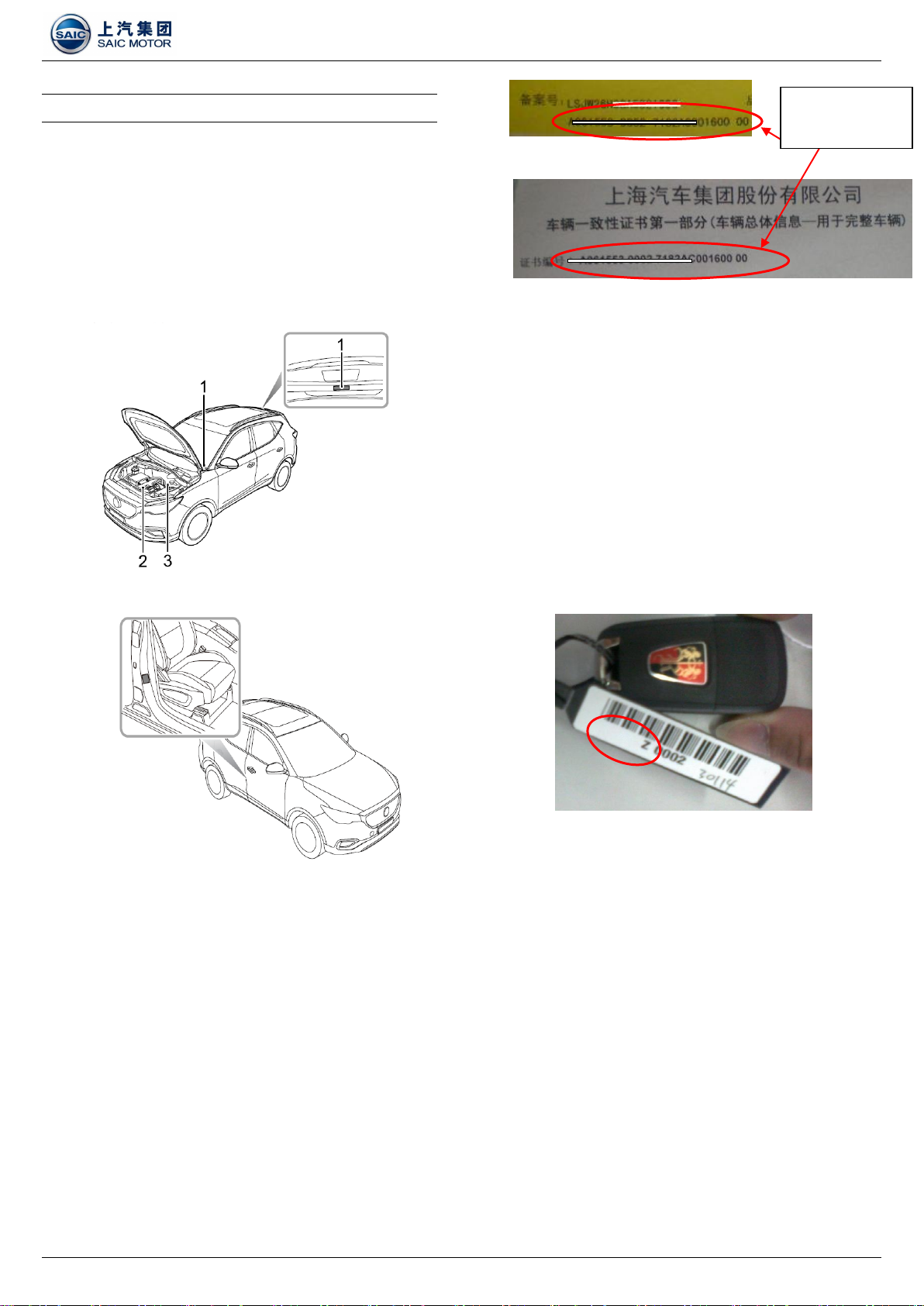
2. High-voltage components in the engine compartment are
shown below:
1) High-voltage Harness.
2) Onboard Charger (OBC).
3) High-voltage Power Distribution Unit (PDU).
4) Electric A/C Heater PTC.
5) High-voltage Battery Pack.
6) Manual Service Switch (MSD).
7) Electric A/C Compressor (EACP).
8) Electric Drive System (EDS).
9) Battery Heater.
10) Slow Charging Port.
11) Fast Charging Port.
VI. Inspection of Battery and Fuse Block and Related
Circuits
1. Check the battery, cable and battery fuse block
Check the battery voltage.
Check if the battery terminal is securely tightened and
free of corrosion.
Check and confirm that the battery is leak-free.
Check that the battery negative cable is securely
grounded.
Check that the fuse is firmly connected in the battery
fuse block without any looseness or interference.
2. Check that the relay/fuse and related harnesses in the
primary fuse block in the engine compartment are free of
looseness or interference;
3. Fuses and relays are all in readiness.
4. The cover of primary fuse block is intact and can be
properly closed.
Passenger Compartment Inspection
I. Key and Lock Function Inspection
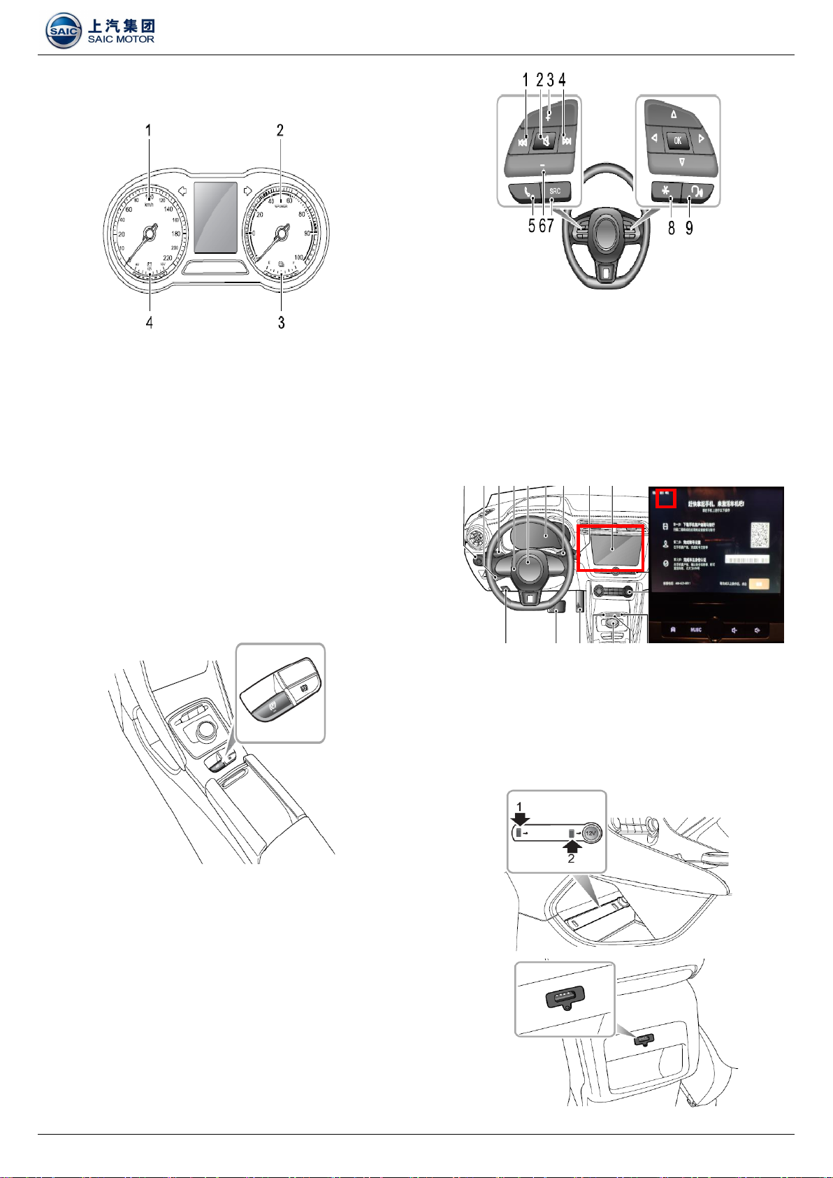
1. At a distance of 1m from the vehicle, press the Unlock,
Lock and Tailgate Release buttons on the key remote
control respectively to confirm that the remote control
functions normally as shown below:
1). Press Unlock button once, the turn signal lamp will
flash once, and confirm that all four doors can be
unlocked.
2). Press Lock button once, the turn signal lamp will
flash three times, and confirm that all four doors can
be locked.
2. Mechanical key function: Confirm that all doors can be
locked by inserting the key into the driver door lock and
then turning clockwise; and all doors can be unlocked by
turning counterclockwise.
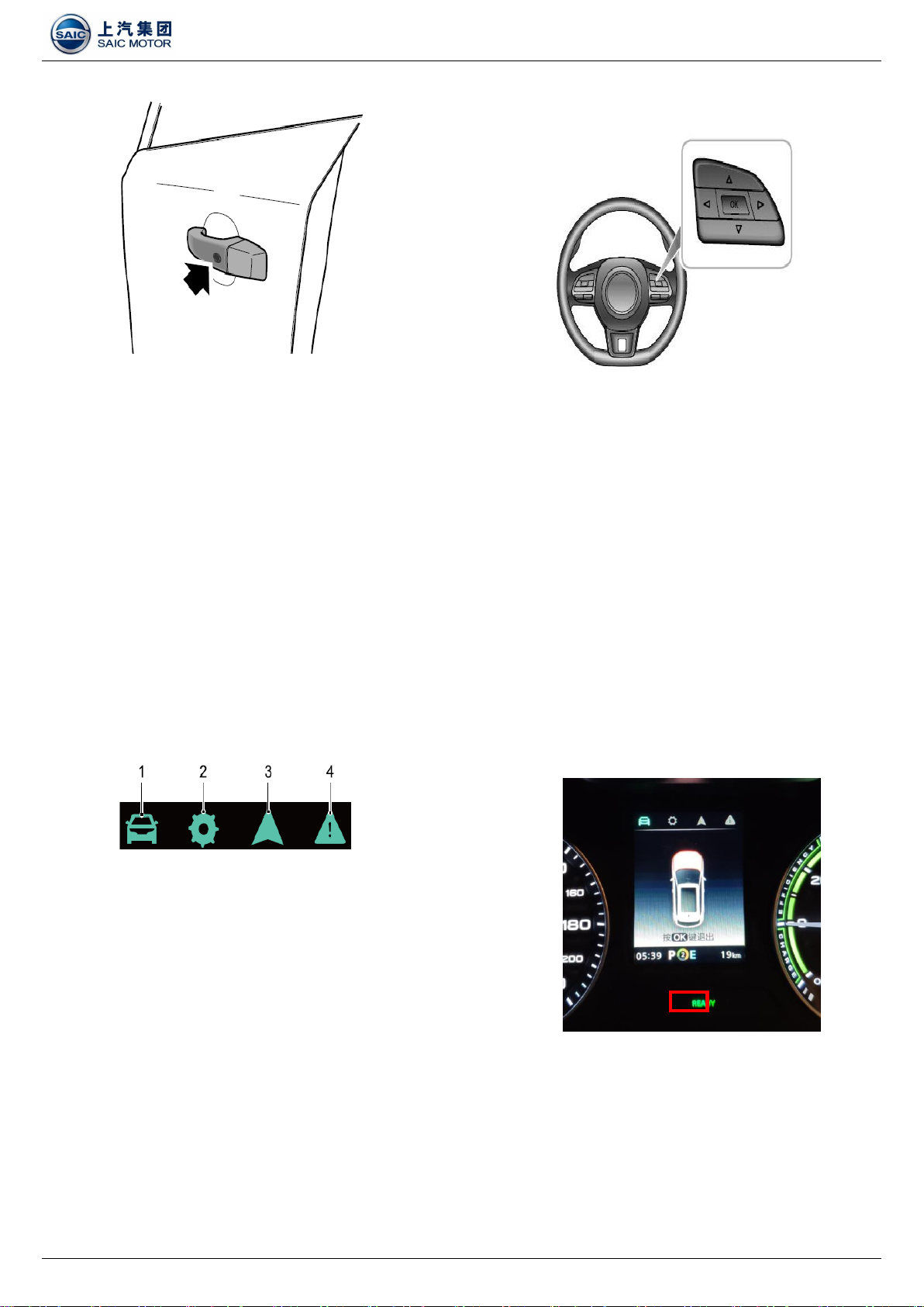
3. Keyless entry function: The keyless entry system can lock
and unlock the doors or open the trunk lid as long as you
carry the remote key and approach the vehicle within a
distance of 1.5m.
1) Keyless Lock: After shutting off the engine, press the
release button on the door handle once (no need to
press the Lock button on the remote key) to lock all
doors before leaving the vehicle. And the vehicle
enters the anti-theft alarm state.
2) Keyless Unlock: Press the release button on the
driver door or passenger door handle once to unlock
1. Front Passenger Side Fuse Block (behind the front
passenger side glove box)
2. Engine Compartment Fuse Block (at the left front side of
engine compartment)
SAIC-PDI Operation Instruction_ZS11E_V1.0_201903
Page 6 of 14
the door, then pull the door handle to open the door.
★The following inspections require to turn on the
ignition switch (the key is placed in position 2)
Special Tip: There are many electronic devices on the
vehicle with great power consumption, so
when each inspection is completed, be sure to
turn off the corresponding switch and do not
use the electronic devices for an extended
period of time to avoid battery drain!!
II. Instrument Pack Inspection
1. Message Centre Setting
1) The message centre provides the followings:
2) Press the LEFT/RIGHT button on the right of the
multifunction steering wheel to shift the display
items.
3) Press the OK button on the right of the multifunction
steering wheel to confirm or reset.
4) Press the UP/DOWN button on the right of
multifunction steering wheel to make adjustment.
2. Instrument Warning Lamp
1) Switch on the ignition, confirm that all warning lamps
will be illuminated to conduct the self-check.
2) Switch on the ignition, confirm that the following
warning lamps remain on upon completion of the
self-check; and they will be extinguished after the
vehicle starts.
Battery Uncharged Warning Lamp
Power Battery OFF Warning Lamp
3. "READY" Indicator and Power Indicator
1) After the vehicle is started, the "READY" indicator on
the instrument panel is normally illuminated.
"READY" will be displayed when the vehicle is
powered on.
The general message provides the followings:
1. Trip Computer
2. Settings
3. Navigation/Music *
4. Failure Message
SAIC-PDI Operation Instruction_ZS11E_V1.0_201903
Page 7 of 14
2) Display of the power battery electric quantity in the
instrument (3).
4. Electronic Parking Brake (EPB) Status Inspection
1) Pull the EPB switch until indicators in the EPB switch
and the instrument pack illuminate, it indicates that
the parking brake is applied. An audible motor noise
may be heard when applying or releasing the EPB.
2) Turn on the ignition switch, step on the brake pedal,
and press the EPB switch; indicators in the EPB
switch and the instrument pack extinguish, it
indicates that the parking brake is disabled.
3) If the EPB malfunction indicator lamp in the
instrument pack is normally on, it indicates that the
EPB has a failure.
III. Entertainment System (Yun OS)
1. Make sure the remote control buttons on the steering
wheel function normally.
2. Touchscreen Function / 4G Network Function
1) Check that the surface of the display is flat and free
of scratches;
2) The contents displayed are intact, without missing
characters, figures or graphs.
3) Check the upper left corner of the touchscreen for
4G network signal.
3. USB Functional Inspection
1) Check if the 5V charging function of three USBs
(front and back) is normal.
2) Check if the data transmission function of two USBs
in the front row is normal.
SAIC-PDI Operation Instruction_ZS11E_V1.0_201903
Page 8 of 14
IV. Light Inspection
1. Operate the master light switch to check if the lights work
properly.
2. AUTO Light Functional Inspection
1) With the ignition switch in position “ACC”, the AUTO
lighting system will be defaulted as ON (1). The
system will automatically switch the width lamps, tail
lamps and backlights on and off according to the
intensity of current ambient light.
2) With the ignition switch in position “ON”, the system
will automatically switch the witch lamps, tail lamps,
switch backlights and dipped beam headlamps on
and off and adjust the backlights of the instrument
and entertainment display according to the intensity
of current ambient light.
3. Follow Me Home Functional Inspection
1) After the ignition switch is turned off, pull the master
light switch backwards. Follow Me Home function is
enabled. And dipped beams and width lamps will
illuminate.
2) This function can be set through the "Vehicle
Settings" interface on the display.
4. Find My Car
1) After the car is locked for 2 minutes, press the LOCK
button on the key, Find My Car function is enabled,
and the turn signal lamp and horn will operate based
on your set state.
2) This function can be set in the "Vehicle Setting"
interface on the display.
V. Parking Aid System
1. This model is provided with rear parking aid system; when
the ignition switch is in position “ON”, the rear parking aid
will be enabled automatically when the reverse gear is
selected; it will be switched off as soon as the reverse
gear is disengaged.
2. A short beep will be given by the parking aid within 1
second after selecting reverse gear to indicate that the
system is starting to work.
3. If an obstacle is detected at the rear, the system will
prompt the driver with warning alarms.
VI. Parking Camera System
The parking camera is fitted between the license plate
lights. When the reverse gear is selected, the obstruction image
will be displayed on the entertainment display to assist the
driver to park the vehicle.
VII. Tailgate Release
1. The tailgate can be opened by the following means:
1) With the ignition switch in position "OFF", long press
the Release button (B) for more than 2 seconds to open the
tailgate;
2) For models with keyless entry, when the valid smart
key is present in 1m range around the tailgate, directly press
the emblem (A) on the tailgate to open the tailgate.
Tailgate Emergency Open
Pull open the plug (as illustrated) with hand, and insert a
small flat-blade screwdriver into the emergency open lock
groove to open the tailgate from the trunk.
SAIC-PDI Operation Instruction_ZS11E_V1.0_201903
Page 9 of 14
VIII. Sunroof Inspection
1. Adjust according to the sunroof switch positions.
Sunroof tilting
Sunroof opening
Sunroof closing
2. Open or close the sunroof sunshade.
IX. Front/Rear Wipers
1. Check and confirm that the surface of the wiper lever is
normal.
2. Check and confirm that the Intermittent Wipe, Normal Wipe,
Fast Wipe and Single Wipe of the front wipers operate
properly and the wiper speed adjustment is normal.
3. Check and confirm that the Intermittent Wipe and Wash
and Wipe of the rear wipers operate properly.
X. Mode Switching Inspection
1. MODE Switching
1) The driving mode of the current vehicle can be
switched by the MODE button:
ECO Mode
Normal Mode
Sport Mode
2) Confirm the vehicle driving mode in the instrument
pack (as shown in the red box below).
2. Brake Energy Recovery Mode Switching
1) The energy recovery mode registration can be set by
switching the UP and Down buttons.
Heavy mode, the instrument displays ;
Moderate mode, the instrument displays ;
Light mode, the instrument displays ;
2) Confirm the vehicle driving mode in the instrument
pack (as shown in the red box below).
SAIC-PDI Operation Instruction_ZS11E_V1.0_201903
Page 10 of 14
3. BATTERY Switching
Manually toggling the switch "frontwards" or "rearwards"
can call out the Distance to Empty message on the
instrument pack interface and the message will disappear
after a few seconds.
★ The following inspections require to turn off the
ignition switch/power off the vehicle
Dash Panel, Rear Penal and Trunk Inspection
I. Vehicle Tool
1. Tyre Repair Kit and Towing Hook
Tyre repair liquid reservoir (1).
Electric air pump (2).
Towing hook (3).
Wheel bolt cap removal tool (4).
Warning triangle (5).
2. Onboard Charging Cable
There is no damage on the appearance.
The charging connection and charging status
indicator lamps are illuminated after connecting with
220V power supply.
No abnormal alarm lamp or malfunction indicator
lamp illuminates.
3. Charging Port Inspection
Opening and closing of fast/slow charging port flap (as
shown below).
Opening and closing of fast/slow charging port cover (as
shown below).
Check the fast/slow charging port for water or other foreign
matters.
Check and confirm that the fast/slow charging port is
properly sealed, and the seal ring is free of aging,
deformation, etc.
During slow charging, check the function of electronic lock
at the charging port.
SAIC-PDI Operation Instruction_ZS11E_V1.0_201903
Page 11 of 14
★ The following inspections require to turn off the
ignition switch/power off the vehicle
Chassis Inspection
I. Power Battery Inspection
1. Check the surface of the power battery pack for no
scratches, deformation, etc.
2. The power battery pack high voltage (4, 5) and low voltage
connectors (3) are firmly connected.
II. EDS Inspection
1. The appearance of EDS is free from oil stain and damage.
2. The EDS cooling circuit has no leakage or interference.
3. The EDS high voltage harness has no damage, and the
circuit has no interference.
4. The EDS low voltage connector is firmly connected and the
circuit has no interference.
III. Electric Compressor Inspection
1. The appearance of the electric compressor is free from oil
leakage and damage.
2. The electric compressor pipeline is reliably connected with
no leakage trace.
3. The high-voltage connector of the electric compressor is
firmly connected with no damage on the circuit.
4. The low-voltage connector of the electric compressor is
firmly connected with no interference in the circuit.
IV. Cooling Parts and Pipeline Connections
1. The cooling system components are free from leakage and
damage, and the pipeline is reliably connected.
2. There is no interference in the cooling system pipeline.
SAIC-PDI Operation Instruction_ZS11E_V1.0_201903
Page 12 of 14
★The following inspections require to turn
off the ignition switch and connect the
charging cable
Slow Charging Functional Inspection
I. Onboard Charging Cable Connection
1. Press the button on the charging handle (as shown below)
until the handle is inserted into the bottom of the charging
socket, then release the button and confirm the secure
connection. When the centre console is locked, the
charging handle should not be pulled out.
2. After connecting the charging cable to the 220V power
supply, confirm relevant indicator lamp in the instrument
panel is illuminated.
II. Slow Charging Function
1. Confirm the charging current when the ignition switch is
placed to position “ON”; the current range is from -1A to
-7A.
2. Read the SOC value before charging, and observe
whether the electric quantity is increased after half an
hour.
Road Test
I. Preparation
1. Adjust the seat position and the angle of interior/exterior
rearview mirror to the proper position.
2. Check the positions (front and back, up and down) of the
steering wheel and make necessary adjustments.
3. Observe the electric quantity of the high-voltage battery
pack. In case of low battery, charge it in time.
4. Start the vehicle to enter the "READY" state.
II. Driving Mode
1. There must be 5 switchings among the working conditions:
acceleration, braking, and coasting.
2. Check the noise of the vehicle while driving.
III. Pedestrian Warning System
System working condition test: start the vehicle, and
control the medium point to select ON
When accelerating, the vehicle speed is greater than
0km/h and less than 30km/h.
When decelerating, the vehicle speed is less than
25km/h but greater than 0km/h.
SAIC-PDI Operation Instruction_ZS11E_V1.0_201903
Page 13 of 14
★The followings can be tested depending
on the road conditions
IV. Constant Speed Cruise Function
1. Cruise Control System Activation
1) Switch the cruise lever to "ON" position, the yellow
cruise indicator on the instrument pack lights on, and
the cruise control system is in Standby state.
2) The system is in Standby state and the current speed
is greater than 30km/h.
2. Function of Each Cruise Functional Button
3. Target Cruise Speed Adjustment
1) Acceleration: Push the lever upwards (1) and hold,
this will increase the speed. Release the lever switch
when the desired speed is reached.
2) Deceleration: Push the lever downwards (2) and hold,
this will decrease the speed. Release the lever
switch when the desired speed is reached.
3) The set speed can be gradually increased or
decreased by turning the lever and immediately
releasing; turning upwards will increase the speed,
while turning downwards will decrease the speed.
Turning the lever once will increase/decrease the
speed appr. 1km/h.
4) When the cruise control system is in operation, the
vehicle still can be accelerated by pressing the
accelerator pedal (such as overtaking). The speed
will return to the original setting value after releasing
the pedal.
V. Auto Hold
1. Auto hold has 3 main states in normal condition:
1) OFF: Function in Off state.
2) Standby: Function in Standby state; the function is
activated but it is not parked. In Standby state, the
vehicle will automatically park once the conditions for
parking are all met.
3) Parking: Function in Parked state. In this case, the
green indicator lamp on the instrument pack
illuminates.
2. Enabling of Auto Hold Function
1) With the driver seat belt fastened, the door closed
and the system ON, press the Auto Hold switch to
bring the Auto Hold function from OFF to Standby
state.
2) With the brake pedal depressed to some extent and
the vehicle fully stopped, the Auto Hold function will
enter Parking state from Standby.
3) When theAuto Hold is in the Parking state, engaging
relevant gear and pressing the accelerator will
automatically release the Auto Hold function.
4) With the Auto Hold in the Parking state, it will result in
the electronic parking brake being applied and the
system exiting the Parking state in some cases (such
as removing the seat belt, switching off the engine
and stopping for a certain time etc.)
VI. Brake Energy Recovery Function
1. Energy recovery is switched among 3 modes, and the
corresponding mode will be displayed on the instrument.
Acceleration (1)
Deceleration (2)
Cancel (3)
ON (4)
Resume (5)
Set (6)
OFF (7)
SAIC-PDI Operation Instruction_ZS11E_V1.0_201903
Page 14 of 14
2. Energy Recovery Effect Assessment
Level 3 - Recover more energy, with short sliding
distance, and strong vehicle drag;
Level 2 - Recover moderate energy;
Level 1 - Recover less energy, with long sliding
distance, and no obvious drag;
Brake
Energy
Recovery
Level: Strong
Brake Energy
Recovery
Level:
Moderate
Brake
Energy
Recovery
Level: Weak
SAIC-PDI Operation Instruction_ZS11E_V1.0_201903
Page 15 of 14
Troubleshooting and Vehicle Settings
I. DTC Inspection and Deletion
1. Connect VDS II, set the ignition switch to position "2", enter the vehicle diagnosis interface, and click the "Start Scanning" button to
complete the vehicle module scan. If there is a DTC, you need to find the specific reason;
2. Click "Delete All DTCs" option to ensure that no DTC exists in each module of the vehicle.

Other SAIC MOTOR Automobile manuals

SAIC MOTOR MG3 2011 User manual

SAIC MOTOR

SAIC MOTOR MG3 2011 User manual

SAIC MOTOR MG HS User manual

SAIC MOTOR

SAIC MOTOR MG HS User manual

Popular Automobile manuals by other brands

Hyundai 2008 Elantra owner's manual

Hyundai

Hyundai 2008 Elantra owner's manual

Subaru 2001 Forester owner's manual

Subaru

Subaru 2001 Forester owner's manual

Porsche 911 TURBO - 1975 WORSHOP manual

Porsche

Porsche 911 TURBO - 1975 WORSHOP manual

Mercedes-Benz C-Class Cabriolet 2018 Operator's manual

Mercedes-Benz

Mercedes-Benz C-Class Cabriolet 2018 Operator's manual

Dodge 2005 Neon SRT4 owner's manual

Dodge

Dodge 2005 Neon SRT4 owner's manual

Volvo V90 cross country owner's manual

Volvo

Volvo V90 cross country owner's manual

Dodge Durango 2016 owner's manual

Dodge

Dodge Durango 2016 owner's manual

Volvo XC60 - ANNEXE 541 owner's manual

Volvo

Volvo XC60 - ANNEXE 541 owner's manual

GMC Sierra 2005 owner's manual

GMC

GMC Sierra 2005 owner's manual

FCA US DODGE CHARGER RWD 2019 user guide

FCA US

FCA US DODGE CHARGER RWD 2019 user guide

Hyundai Santa Fe 2006 owner's guide

Hyundai

Hyundai Santa Fe 2006 owner's guide

Chevrolet Silverado EV 2024 instruction manual

Chevrolet

Chevrolet Silverado EV 2024 instruction manual

Toyota 2013 FJ Cruiser Specifications

Toyota

Toyota 2013 FJ Cruiser Specifications

Toyota Celica 2002 owner's manual

Toyota

Toyota Celica 2002 owner's manual

Dodge Challenger 2013 user guide

Dodge

Dodge Challenger 2013 user guide

GMC 2012 GMC Canyon Catalog

GMC

GMC 2012 GMC Canyon Catalog

Volkswagen Karmann Chia 1500 instruction manual

Volkswagen

Volkswagen Karmann Chia 1500 instruction manual

Skoda 2009 Yeti owner's manual

Skoda

Skoda 2009 Yeti owner's manual

manuals.online logo
manuals.online logoBrands
  • About & Mission
  • Contact us
  • Privacy Policy
  • Terms and Conditions

Copyright 2025 Manuals.Online. All Rights Reserved.