Samsung me18h704sfs User manual

Installation Instructions
Over The Range Microwave Oven
BEFORE YOU BEGIN (Read these instructions completely and carefully.)
IMPORTANT Save these instructions for local inspector’s use.
IMPORTANT Observe all governing codes and ordinances.
• Note to Installer - Be sure to leave these instructions with the Consumer.
• Note to Consumer - Keep these instructions for future reference.
• Skill level - Installation of this appliance requires basic mechanical and electrical skills.
• Proper installation is the responsibility of the installer.
• Product failure due to improper installation is not covered under the Warranty.
READ CAREFULLY. KEEP THESE INSTRUCTIONS.
SMH1927_XAC_DE68-04108B-06_EN+CFR.indb 1SMH1927_XAC_DE68-04108B-06_EN+CFR.indb 1 2022-01-20 �� 10:19:072022-01-20 �� 10:19:07

2
Contents
1. Placement of the mounting plate. . . . . . 8
A. Removing the microwave oven from the
carton/Removing the mounting plate. . . . 8
B. Finding the wall studs . . . . . . . . . . . . . . . . 8
C. Determining wall plate location under your
cabinet . . . . . . . . . . . . . . . . . . . . . . . . . . . . 9
D. Aligning the wall plate. . . . . . . . . . . . . . . 10
2. Ventilation types (choose a, b or c) . . . 11
A. Outside top exhaust
(vertical duct). . . . . . . . . . . . . . . . . . . . . . 12
A1. Installation procedure for the exhaust
adaptor and proper damper operation
check . . . . . . . . . . . . . . . . . . . . . . . . . . 12
A2. Adjust the exhaust adaptor . . . . . . . . 12
B. Recirculating
(non-vented ductless) . . . . . . . . . . . . . . . 12
B1. Adapting the microwave blower for
recirculation . . . . . . . . . . . . . . . . . . . . . 12
B2. Installing the charcoal filter. . . . . . . . . 13
C. Outside back exhaust (horizontal duct) . 14
C1. Adapting the microwave blower for
outside back exhaust . . . . . . . . . . . . . 14
3. Installation . . . . . . . . . . . . . . . . . . . . . . . 15
A. Preparing the rear wall for outside back
exhaust . . . . . . . . . . . . . . . . . . . . . . . . . . 15
B. Attach the mounting plate to the wall . . 15
C. Use the top cabinet template to
prepare the top cabinet . . . . . . . . . . . . . 16
D. Mount the microwave oven . . . . . . . . . . 16
E. Connecting ductwork for outside top
exhaust . . . . . . . . . . . . . . . . . . . . . . . . . . 17
4. Before you use your microwave . . . . . 18
Step-by-step installation guide
Important safety instructions. . . . . . . . . . . 3
Electrical requirements. . . . . . . . . . . . . . . . 3
Hood exhaust. . . . . . . . . . . . . . . . . . . . . . . . 4
Damage - Shipment/Installation . . . . . . . . 6
Parts included . . . . . . . . . . . . . . . . . . . . . . . 6
Tools you will need . . . . . . . . . . . . . . . . . . . 7
Mounting space. . . . . . . . . . . . . . . . . . . . . . 7
General information
SMH1927_XAC_DE68-04108B-06_EN+CFR.indb 2SMH1927_XAC_DE68-04108B-06_EN+CFR.indb 2 2022-01-20 �� 10:19:072022-01-20 �� 10:19:07

3
General information
IMPORTANT SAFETY INSTRUCTIONS
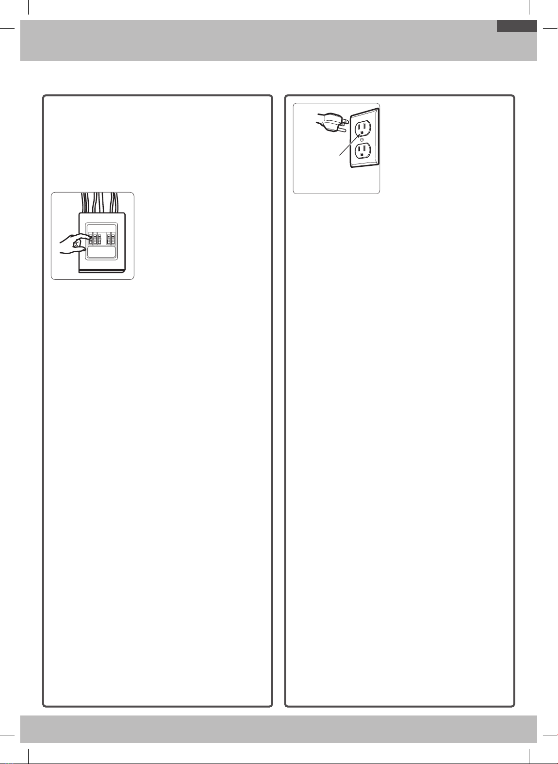
This product requires a three-prong grounded outlet.
The installer must perform a ground continuity check on
the power outlet box before beginning the installation
to insure that the outlet box is properly grounded. If
not properly grounded, or if the outlet box does not
meet electrical requirements noted (under ELECTRICAL
REQUIREMENTS), a qualified electrician should be
employed to correct any deficiencies.
Insure proper
ground exists
before use
CAUTION: For personal
safety, remove house fuse or
open circuit breaker before
beginning installation to
avoid severe or fatal shock
injury.
CAUTION: For personal safety, the mounting
surface must be capable of supporting the cabinet
load, in addition to the added weight of this 69
pound product, plus additional oven loads of up to
50 pounds or a total weight of 109 pounds.
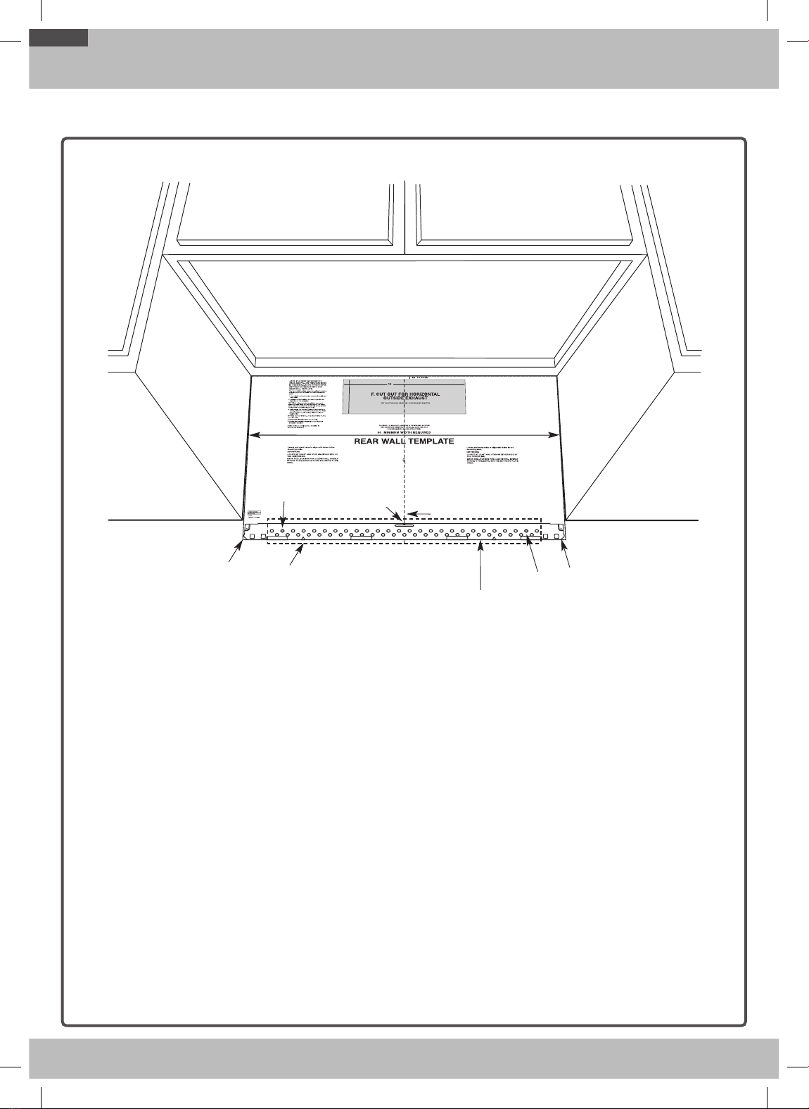
CAUTION: For personal safety, this product cannot
be installed in cabinet arrangements such as an
island or a peninsula. It must be mounted to BOTH
a top cabinet AND a wall.
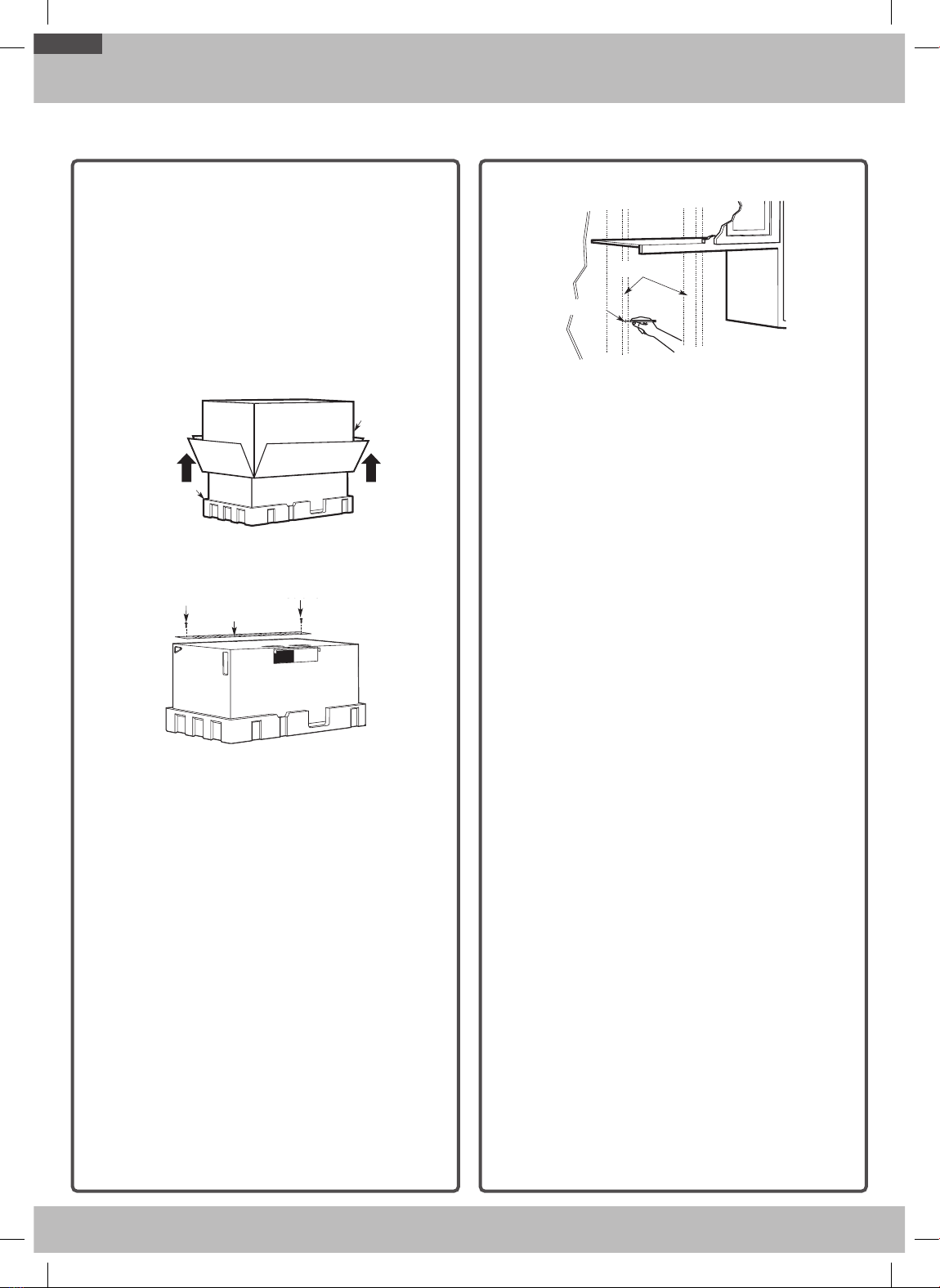
NOTE: For easier installation and personal safety,
it is recommended that two people install this
product.
IMPORTANT – PLEASE READ CAREFULLY. FOR
PERSONAL SAFETY, THIS APPLIANCE MUST BE
PROPERLY GROUNDED TO AVOID SEVERE OR
FATAL SHOCK.
Insure proper
ground exists
before use
Insure proper
ground exists
before use.
The power cord of this
appliance is equipped with a
three-prong (grounding) plug
which mates with a standard
three-prong (grounding) wall
receptacle to minimize the
possibility of electric shock
hazard from this appliance.
You should have the wall receptacle and circuit
checked by a qualified electrician to make sure the
receptacle is properly grounded.
If you have a standard two-prong wall receptacle,
it is very important to have it replaced with a
properly grounded three-prong wall receptacle,
installed by a qualified electrician.
DO NOT, UNDER ANY CIRCUMSTANCES, CUT,
DEFORM OR REMOVE ANY OF THE PRONGS
FROM THE POWER CORD. DO NOT USE WITH AN
EXTENSION CORD.
ELECTRICAL
REQUIREMENTS
Product rating is 120 volts AC, 60 Hertz. This product
must be connected to a supply circuit of the proper
voltage and frequency. Wire size must conform to the
requirements of the National Electrical Code or the
prevailing local code for this kilowatt rating. The power
supply cord and plug should be brought to a separate
branch circuit single grounded outlet of at least 15 A
and max of 20 A. 20 A is recommended for multifamily
buildings. The outlet box should be located in the
cabinet above the microwave oven. The outlet box and
supply circuit should be installed by a qualified electrician
and conform to the National Electrical Code or the
prevailing local code.
SMH1927_XAC_DE68-04108B-06_EN+CFR.indb 3SMH1927_XAC_DE68-04108B-06_EN+CFR.indb 3 2022-01-20 �� 10:19:072022-01-20 �� 10:19:07

4
General information
NOTE: Read these next two pages only if you plan to vent your exhaust to the outside. If you plan to recirculate
the air back into the room, proceed to page 11.
OUTSIDE TOP EXHAUST (EXAMPLE ONLY)
The following chart contains an example of one possible ductwork installation.
DUCT PIECES EQUIVALENT
LENGTH x NUMBER USED = EQUIVALENT
LENGTH
Roof Cap 24 ft. x (1) = 24 ft.
12 Ft. Straight Duct
(6˝ Round) 12 ft. x (1) = 12 ft.
Rectangular-to-Round
Transition Adaptor* 5 ft. x (1) = 5 ft.
Equivalent lengths of duct pieces are based on actual tests
and reflect requirements for good venting performance with
any vent hood.
Total Length = 41 ft.
* IMPORTANT: If a rectangular-to-round transition adaptor is used, the bottom corners of the damper will have to be cut to
fit, using the tin snips, in order to allow free movement of the damper.
OUTSIDE BACK EXHAUST (EXAMPLE ONLY)
The following chart contains an example of one possible ductwork installation.
DUCT PIECES EQUIVALENT
LENGTH x NUMBER USED = EQUIVALENT
LENGTH
Wall Cap 40 ft. x (1) = 40 ft.
3 Ft. Straight Duct
(3 ¼˝ x 10˝ Rectangular)
3 ft. x (1) = 3 ft.
90 ° Elbow 10 ft. x (2) = 20 ft.
Equivalent lengths of duct pieces are based on actual tests
and reflect requirements for good venting performance with
any vent hood.
Total Length = 63 ft.
NOTE: For back exhaust, care should be taken to align the exhaust with the space between studs, or the wall should be
prepared at the time it is constructed by leaving enough space between the wall studs to accommodate exhaust.
HOOD EXHAUST
SMH1927_XAC_DE68-04108B-06_EN+CFR.indb 4SMH1927_XAC_DE68-04108B-06_EN+CFR.indb 4 2022-01-20 �� 10:19:072022-01-20 �� 10:19:07

5
General information
NOTE: If you need to install ducts, note that the total duct
length of 3 ¼˝ x 10˝ rectangular or 6˝ diameter round duct
should not exceed 140 equivalent feet.
Outside ventilation requires a HOOD EXHAUST DUCT.
Read the following carefully.
NOTE: It is important that venting be installed using the
most direct route and with as few elbows as possible.
This ensures clear venting of exhaust and helps prevent
blockages. Also, make sure dampers swing freely and
nothing is blocking the ducts.
Exhaust connection:
The hood exhaust has been designed to mate with a
standard 3 ¼˝ x 10˝ rectangular duct.
If a round duct is required, a rectangular-to-round
transition adaptor must be used. Do not use less than
a 6˝ diameter duct.
Maximum duct length:
For satisfactory air movement, the total duct length of
3 ¼˝ x 10˝ rectangular or 6˝ diameter round duct should not
exceed 140 equivalent feet.
Elbows, transitions, wall and roof caps,
etc., present additional resistance to airflow and are
equivalent to a section of straight duct which is longer than
their actual physical size. When calculating the total duct
length, add the equivalent lengths of all transitions and
adaptors plus the length of all straight duct sections. The
chart below shows you how to calculate total equivalent
ductwork length using the equivalent length in feet of some
typical ducts.
DUCT PIECES EQUIVALENT
LENGTH x NUMBER USED = EQUIVALENT
LENGTH
Rectangular-to-Round
Transition Adaptor* 5 ft. x ( ) = ft.
Wall Cap 40 ft. x ( ) = ft.
90 ° Elbow 10 ft. x ( ) = ft.
45 ° Elbow 5 ft. x ( ) = ft.
90 ° Elbow 25 ft. x ( ) = ft.
45 ° Elbow 5 ft. x ( ) = ft.
Roof Cap 24 ft. x ( ) = ft.
Straight Duct 6˝ Round or
3 ¼˝ x 10˝ Rectangular 1 ft. x ( ) = ft.
Total Ductwork = ft.
* IMPORTANT: If a rectangular-to-round
transition adaptor is used, the bottom
corners of the damper will have to be cut
to fit, using tin snips, in order to allow free
movement of the damper.
Equivalent lengths of duct pieces are based
on actual tests and reflect the requirements
for good venting performance with any vent
hood.
SMH1927_XAC_DE68-04108B-06_EN+CFR.indb 5SMH1927_XAC_DE68-04108B-06_EN+CFR.indb 5 2022-01-20 �� 10:19:072022-01-20 �� 10:19:07

6
General information
• If the unit is damaged in shipment, return the unit to the store in which it was bought for repair or replacement.
• If the unit is damaged by the customer, repair or replacement is the responsibility of the customer.
• If the unit is damaged by the installer (if other than the customer), repair or replacement must be made by
arrangement between the customer and installer.
DAMAGE - SHIPMENT/INSTALLATION
HARDWARE PACKET
PART QUANTITY
Template
INSTALLATION
INSTRUCTIONS
Wood Screws
(¼˝ x 2˝) 1
Template
INSTALLATION
INSTRUCTIONS
Toggle Bolts
(and wing nuts)
(3/16˝ x 3˝)
2
Template
INSTALLATION
INSTRUCTIONS
Self-aligning Machine
Screws (¼˝ - 28 x 3 ¼˝) 2
You will find the installation hardware contained in a packet
with the unit. Check to make sure you have all these parts.
NOTE: Some extra parts are included.
ADDITIONAL PARTS
PART QUANTITY
TOP CABINET TEMPLATE
REAR WALL TEMPLATE
Top Cabinet Template 1
TOP CABINET TEMPLATE
REAR WALL TEMPLATE Rear Wall Template 1
Installation Instructions 1
One Touch Easy
Grease Filter
1
(Installed)
Template
INSTALLATION
INSTRUCTIONS
Exhaust adaptor 1
PARTS INCLUDED
SMH1927_XAC_DE68-04108B-06_EN+CFR.indb 6SMH1927_XAC_DE68-04108B-06_EN+CFR.indb 6 2022-01-20 �� 10:19:082022-01-20 �� 10:19:08

7
General information
#1 and #2 Phillips
screwdriver
Pencil Ruler or tape measure and
straight edge
Carpenter square (optional)
Tin snips
(for cutting damper,
if required)
Scissors
(to cut template,
if necessary)
Electric drill with 3/16˝,
½˝ and ⅝˝ drill bits
Filler blocks or scrap wood
pieces, if needed for top
cabinet spacing (used on
recessed bottom cabinet
installations only)
Gloves Saw (saber, hole or keyhole) Stud finder or Hammer
(optional)
Safety goggles
Level Duct and masking tape
TOOLS YOU WILL NEED
16 ¹⁵∕₁₆˝
30˝
5˝
30˝ min.
Bottom edge of the
cabinet needs to be
30˝ or more from the
cooking surface.
Backsplash
12˝ max.
NOTES:
• The space between the cabinets must be 30˝ wide and
free of obstructions.
• This microwave oven is for installation over ranges up
to 36˝ wide.
• If you are going to vent your microwave oven to the
outside, see the Hood Exhaust Section for exhaust
duct preparation.
• If installing the microwave oven beneath smooth
flat cabinets, be careful to follow the instructions
on the top cabinet template for power cord
clearance.
• Maximum cabinet depth above and beside the
unit is 12˝.
• The dimensions provided are the minimum
required for mounting the microwave oven. Local
codes and the practical use of the range will
likely require you to provide more than the 13.5˝
shown between the range and the bottom of the
microwave.
MOUNTING SPACE
SMH1927_XAC_DE68-04108B-06_EN+CFR.indb 7SMH1927_XAC_DE68-04108B-06_EN+CFR.indb 7 2022-01-20 �� 10:19:082022-01-20 �� 10:19:08

8
Step-by-step installation guide
1. PLACEMENT OF THE MOUNTING PLATE
A. REMOVING THE MICROWAVE OVEN
FROM THE CARTON/REMOVING THE
MOUNTING PLATE
1. Remove the installation instructions, Exhaust
adaptor, filters, glass tray, and the small hardware
bag. Do not remove the Styrofoam protecting the
front of the oven.
2. Fold back all 4 carton flaps fully against carton
sides. Then carefully roll the oven and carton over
onto the top side. The oven should be resting in the
Styrofoam.
Styrofoam
Carton
Carton
Styrofoam
3. Pull the carton up and o the oven.
4. Remove and properly discard plastic bags.
Screws Screws
Mounting Plate
Screws
Mounting Plate
Screws
5. Remove the 2 screws from the mounting plate. This
plate will be used as the rear wall template and for
mounting.
NOTE: You will have to reuse two screws in original
loction of outcase after removing mounting plate.
B. FINDING THE WALL STUDS
Wall Studs
Center
Center
Wall Studs
1. Find the studs using one of the following methods:
A. Stud finder–a magnetic device which locates nails.
OR
B. Use a hammer to tap lightly across the mounting
surface to find a solid sound. This will indicate a
stud location.
2. After locating the stud(s), find the stud’s center by
probing the wall with a small nail to find the edges of
the stud. Then, place a mark halfway between the
edges. The center of any adjacent studs should be
16˝ or 24˝ from this mark.
3. Draw a line down the center of the studs.
THE MICROWAVE MUST BE CONNECTED TO AT
LEAST ONE WALL STUD.
SMH1927_XAC_DE68-04108B-06_EN+CFR.indb 8SMH1927_XAC_DE68-04108B-06_EN+CFR.indb 8 2022-01-20 �� 10:19:082022-01-20 �� 10:19:08

9
Step-by-step installation guide
C. DETERMINING WALL PLATE
LOCATION UNDER YOUR CABINET
Plate position – beneath flat bottom cabinet.
C
L
16 ¹⁵∕₁₆˝
At least 30˝
Draw a vertical line on the wall at the center of the 30˝
wide space. Tape the Rear Wall Template onto the wall
so that the top of the template touches the bottom of the
cabinet and the centerline on the template lines up with
the line you drew on the wall.
Plate position – beneath recessed bottom cabinet
with front overhang.
`
i
Plate position – beneath recessed bottom
cabinet with front overhang
Draw a line on the
back wall equal to the
depth of the front
overhang.
30" to Cooktop
30˝ to Cooktop
Draw a horizontal
line to mark how far
the inside of the front
overhang descends
below the cabinet.
Plate position – beneath framed recessed cabinet
bottom.
C
L
30˝ to Cooktop
Draw a vertical line on the wall at the center of the 30˝
wide space. Tape the Rear Wall Template onto the wall
so that the top of the template touches the bottom of the
cabinet frame and the centerline on the template lines up
with the line you drew on the wall.
Your cabinets may have decorative trim that interferes
with the microwave installation. Remove the decorative
trim to install the microwave properly and to make it
level.
THE MICROWAVE MUST BE LEVEL.
Use a level to make sure the cabinet bottom is level.
Draw a vertical line on the wall at the center of the 30˝
wide space. Draw a second, horizontal line on the wall
below the cabinet to mark how far the inside of the
front overhang descends below the cabinet. Tape the
Rear Wall Template onto the wall so that the top of the
template touches the bottom of the horizontal line and
the centerline on the template lines up with the vertical
line.
SMH1927_XAC_DE68-04108B-06_EN+CFR.indb 9SMH1927_XAC_DE68-04108B-06_EN+CFR.indb 9 2022-01-20 �� 10:19:092022-01-20 �� 10:19:09

10
Step-by-step installation guide
D. ALIGNING THE WALL PLATE
C
L
CAUTION: Wear gloves to avoid cutting
fingers on sharp edges.
Area E Hole B
Hole A Centerline
notches
Draw a Vertical Line
on Wall from Center
of Top Cabinet
Draw a Horizontal line on wall from
bottom of “Rear Wall Template”.
Horizontal Line
Horizontal Line
Draw a Horizontal line on wall from
bottom of “Rear Wall Template”.
Draw a Horizontal line
on the wall along
the bottom of
“Rear Wall Template”.
Horizontal Line
Horizontal Line Area E
Centerline
notches
Hole A
Hole B
CAUTION: Wear gloves to avoid cutting fingers on
sharp edges.
1. Draw a Horizontal line on the wall at the bottom
of the “Rear Wall Template”.
2. Drill ⅝˝ holes for toggle bolts in 3 locations
(Hole A, Hole B, Hole C) as shown in the
illustration above. If the location of a hole lines up
with a stud, drill a 3/16˝ hole for a wood screw.
You cannot use a toggle bolt to attach the wall
plate to a stud.
NOTE: DO NOT MOUNT THE PLATE AT THIS
TIME.
3. Holes A, B and C are inside area E. If none of
these holes line up with a stud, find a stud in area
E that lines up with a hole circle in Area E, and
then drill a 3/16˝ hole into it for a wood screw. You
must have at least one wood screw mounted
firmly into a stud to support the weight of the
microwave. Set the mounting plate aside.
SMH1927_XAC_DE68-04108B-06_EN+CFR.indb 10SMH1927_XAC_DE68-04108B-06_EN+CFR.indb 10 2022-01-20 �� 10:19:092022-01-20 �� 10:19:09

11
Step-by-step installation guide
2. VENTILATION TYPES (CHOOSE A, B OR C)
This microwave oven is compatible with the following three
types of ventilation:
A. Outside Top Exhaust (Vertical Duct)
B. Recirculating (Non-Vented Ductless)
C. Outside Back Exhaust (Horizontal Duct)
NOTE: This microwave is shipped assembled for Outside
Top Exhaust (except for non-vented models). An exhaust
adaptor is shipped assembled and attached to the filler-
upper. Select the type of ventilation required for your
installation and proceed to that section.
A. OUTSIDE TOP EXHAUST
(VERTICAL DUCT)
B. RECIRCULATING
(NON-VENTED DUCTLESS)
Adaptor in Place
for Outside
Top Exhaust
Adaptor in Place
for Outside Top
Exhaust
See page 12 See page 13
A Charcoal Filter Accessory Kit is required for the
nonvented exhaust. (See your Owner’s Manual for the kit
number.)
C. OUTSIDE BACK EXHAUST
(HORIZONTAL DUCT)
See page 14
SMH1927_XAC_DE68-04108B-06_EN+CFR.indb 11SMH1927_XAC_DE68-04108B-06_EN+CFR.indb 11 2022-01-20 �� 10:19:092022-01-20 �� 10:19:09

12
Step-by-step installation guide
A. OUTSIDE TOP EXHAUST
(VERTICAL DUCT)
A1. INSTALLATION PROCEDURE FOR THE
EXHAUST ADAPTOR AND PROPER DAMPER
OPERATION CHECK
Blower Plate
Damper
Exhaust Adaptor
Retaining Hooks
Back of
Microwave
Oven
1. Slide the exhaust adaptor as shown in the diagram
above.
2. Make sure the tape securing the damper is removed
and damper pivots easily before you mount the
microwave.
CAUTION: You will need to make adjustments to assure
proper alignment with your house exhaust duct after the
microwave is installed.
A2. ADJUST THE EXHAUST ADAPTOR
After you have installed the microwave, you will need to
open the top cabinet and adjust the exhaust adaptor so
that you can connect it to the house duct.
Damper
For Side-toSide
Adjustment, Slide the
Exhaust Adaptor as
Needed
Back of
Microwave
Oven
NOTE: You must attach the house duct to the exhaust
adaptor after installation is complete.
House Duct
House Duct
B. RECIRCULATING
(NON-VENTED DUCTLESS)
B1. ADAPTING THE MICROWAVE BLOWER FOR
RECIRCULATION
1. Remove and save screw that holds blower plate to
microwave.
2. Lift up the blower plate.
Back of
Microwave Oven
Blower
Retaining
Screws
NOTE: The exhaust adaptor with the damper is not
needed for recirculating models. You may want to save
them for possible future use.
SMH1927_XAC_DE68-04108B-06_EN+CFR.indb 12SMH1927_XAC_DE68-04108B-06_EN+CFR.indb 12 2022-01-20 �� 10:19:092022-01-20 �� 10:19:09

13
Step-by-step installation guide
3. Remove the screw that holds the blower motor
and carefully pull out the blower unit. The wires will
extend far enough to allow you to adjust the blower
unit.
CAUTION: To avoid breaking or cracking the blower
blade, do not touch the blade. Hold the outer case of the
blower when you pull it out or put it back in place.
4. Roll the blower unit 90° so that the fan blade
openings are facing toward the front of the
microwave.
Before Roll After Roll
5. Place the blower unit back into the opening.
CAUTION: Do not pull or stretch the blower unit wiring.
Make sure the wires are not pinched.
6. Remove the metal vent fan cover on the back of the
microwave by sliding it up.
7. Close the blower door. Slide blower shield onto the
top of the blower door opening.
8. Secure the blower to the microwave using the blower
retaining screws from Step 1.
Back of
Microwave Oven
Blower Retaining
Screws
Blower Retaining
Screw
B2. INSTALLING THE CHARCOAL FILTER
1. Remove the screws on the top of the grill using a #1
Phillips screwdriver.
2. Open the door.
3. Remove the grill.
• Push the grill left, and then pull the grill straight o.
Charcoal filter
4. Install the charocal filter. When properly installed,
the wire mesh of the filter should be visible from the
front.
5. Reinstall the grille and the screws.
6. Close the door.
Insert mesh-side up
SMH1927_XAC_DE68-04108B-06_EN+CFR.indb 13SMH1927_XAC_DE68-04108B-06_EN+CFR.indb 13 2022-01-20 �� 10:19:102022-01-20 �� 10:19:10

14
Step-by-step installation guide
C. OUTSIDE BACK EXHAUST (HORIZONTAL DUCT)
C1. ADAPTING THE MICROWAVE BLOWER FOR
OUTSIDE BACK EXHAUST
1. Remove and save screw that holds blower Plate to
microwave.
Back of
Microwave Oven
Blower
Retaining
Screws
2. Open the blower door by lifting it up at the back
of the microwave. Remove and save the blower
shield on the back of the microwave by sliding it up.
Remove and save the metal vent fan cover on the
back of the microwave by sliding it up.
3. Carefully pull out the blower unit. The wires will
extend far enough to allow you to adjust the blower
unit.
BEFORE: Fan Blade
Openings Facing Forward
End B
End A
CAUTION: To avoid breaking or cracking the blower
blade, do not touch the blade. Hold the outer case of the
blower when you pull it out or put it back in place.
4. Remove Parts “A” with tin snips or pliers.
Parts “A”
5. Rotate the blower unit counterclockwise 180 °.
Before Rotation After Rotation
Back of Microwave Back of Microwave
6. Place the blower unit back into the opening.
AFTER: Fan Blade
Openings Facing Back
End B
End A
CAUTION: Do not pull or stretch the blower unit
wiring. Make sure the wires are not pinched.
NOTE: The blower unit exhaust openings should
match exhaust openings on the rear of microwave
oven.
7. Close the blower door. Slide blower shield onto the
top of the blower door opening. Secure the blower
to the microwave oven using the blower retaining
screws from Step 1 except the upper blower motor
retaining screw.
Blower
Retaining Screw
Blower Shield
Blower
Retaining Screw
Back of
Microwave Oven
8. Slide the exhaust adaptor onto the back of the
microwave oven, securing it into the lower locking
tabs. Take care to ensure that the damper hinge is
installed so that it is at the top and that the damper
swings freely. Reinstall the upper blower motor screw
through the adaptor and the blower door and into
the back of the microwave oven.
Guide
Guide
Adaptor Locking Tabs
(not shown)
Blower Motor Door
Retaining Screw
Back of
Microwave Oven
SMH1927_XAC_DE68-04108B-06_EN+CFR.indb 14SMH1927_XAC_DE68-04108B-06_EN+CFR.indb 14 2022-01-20 �� 10:19:102022-01-20 �� 10:19:10

15
Step-by-step installation guide
B. ATTACH THE MOUNTING PLATE TO
THE WALL
Attach the plate to the wall using toggle bolts. At least
one wood screw must be used to attach the plate to a
wall stud.
1. Remove the toggle wings from the bolts.
2. Insert the bolts into the mounting plate through
the holes designated to go into drywall, and then
reattach the toggle wings so that ¾˝ of the bolt
protrudes beyond the wing.
INSTALLATION OVERVIEW
A. Prepare Rear Wall (horizontal duct only)
B. Attach Mounting Plate to Wall
C. Prepare Top Cabinet
D. Mount the Microwave Oven
E. Connecting Ductwork (vertical duct only)
A. PREPARING THE REAR WALL FOR
OUTSIDE BACK EXHAUST
You need to cut an opening in the rear wall for outside
exhaust.
C
L
• Read the instructions for outside back exhaust on the
REAR WALL TEMPLATE.
• Tape the REAR WALL TEMPLATE to the rear wall.
• Cut the opening, following the instructions on the
REAR WALL TEMPLATE.
CAUTION: Do not cut an opening in the rear wall if you
are installing the microwave with vertical duct or non-
vented ductless ventilation.
3. INSTALLATION
SMH1927_XAC_DE68-04108B-06_EN+CFR.indb 15SMH1927_XAC_DE68-04108B-06_EN+CFR.indb 15 2022-01-20 �� 10:19:112022-01-20 �� 10:19:11

16
Step-by-step installation guide
To use toggle bolts:
Wall
Toggle Wings
Toggle
Bolt
Bolt End
Spacing for Toggles More
Than Wall Thickness
Mounting
Plate
Spacing for Toggles More
Than Wall Thickness
Bolt End
Mounting
Plate Toggle
Bolt
Wall
Toggle Wings
3. Place the mounting plate against the wall and insert
the toggle wings into the holes in the wall to mount
the plate.
NOTE: Before tightening the toggle bolts and wood
screw, make sure the bottom of the Mounting plate
runs along the bottom Horizontal line of the “Rear wall
Template” and the Mounting plate is properly centered
under the cabinet.
CAUTION: Be careful to avoid pinching your fingers
between the back of the mounting plate and the wall.
4. Tighten all bolts. Pull the plate away from the wall to
help tighten the bolts. Tighten the screw.
C. USE THE TOP CABINET TEMPLATE
TO PREPARE THE TOP CABINET
You need to drill holes for the top support screws and a
hole large enough for the power cord to fit through.
• Read the instructions on the TOP CABINET
TEMPLATE.
• Tape it underneath the top cabinet.
• Drill the holes, following the instructions on the TOP
CABINET TEMPLATE.
CAUTION: Wear safety goggles when drilling holes in
the cabinet bottom.
D. MOUNT THE MICROWAVE OVEN
FOR EASIER INSTALLATION AND PERSONAL SAFETY,
WE RECOMMEND THAT TWO PEOPLE INSTALL THIS
MICROWAVE OVEN.
IMPORTANT: Do not grip or use the handle during
installation.
NOTE: If your cabinet is metal, use the nylon grommet in
the power cord hole to prevent the cord from being cut.
NOTE: Filler blocks are required when mounting this
unit under any cabinet with a recessed bottom or front
overhang. (See page 9.)
IMPORTANT: The case damage that will occur
from over tightening screws if you do not use filler
blocks is not covered under warranty.
IMPORTANT: For models with the grease filter
installed, don’t push up on the filter when you
mount the oven.
Grease Filter
Grease Filter
Grease Filter
Grease Filter
NOTE: When mounting the microwave oven, thread
the power cord through hole in the bottom of the top
cabinet. Keep it tight throughout Steps 1–3. Do not
pinch the cord or lift the oven by pulling cord.
SMH1927_XAC_DE68-04108B-06_EN+CFR.indb 16SMH1927_XAC_DE68-04108B-06_EN+CFR.indb 16 2022-01-20 �� 10:19:112022-01-20 �� 10:19:11

17
Step-by-step installation guide
1. Lift the microwave, tilt it
forward, and hook the slots
at the back bottom edge
onto the four lower tabs of
the mounting plate.
2. Rotate the front
of the oven
up against the
cabinet bottom.
3. Insert a self-aligning screw through the top center
cabinet hole. Temporarily secure the oven by turning
the screw at least two full turns after the threads
have engaged. (It will be completely tightened later.)
Be sure to keep the power cord tight. Be careful
not to pinch the cord, especially when mounting
flush to the bottom of cabinet.
Cabinet Front
Filler Block
Microwave Oven Top
Self-Aligning Screw
Equivalent to
Depth of
Cabinet Recess
Cabinet Bottom Shelf
Equivalent to
Depth of Cabinet
Recess
Cabinet Bottom Shelf
Microwave Oven Top
Cabinet Front
Filler Block
Self-Aligning Screw
4. Attach the microwave oven to the top cabinet.
5. Insert the 2 self-aligning screws through the cabinet
bottom shelf and filler block into the outer top cabinet
of the unit. Continue to support the unit until both
screws are inserted and engaged at least two full
turns, then fully tighten both screws until the unit is
secure.
6. Install the grease filters. See the Owner’s Manual
packed with the microwave for instructions.
NOTE: For models with installed grease filters, you do
not need to install a filter.
E. CONNECTING DUCTWORK FOR
OUTSIDE TOP EXHAUST
House Duct
House Duct
1. Extend the house duct down to connect to the
exhaust adaptor.
2. Seal the exhaust duct joints using duct tape.
SMH1927_XAC_DE68-04108B-06_EN+CFR.indb 17SMH1927_XAC_DE68-04108B-06_EN+CFR.indb 17 2022-01-20 �� 10:19:112022-01-20 �� 10:19:11

18
Before You Use Your Microwave
1. Make sure the microwave oven has been installed
according to instructions.
2. Remove all packing material from the microwave
oven.
3. Install the turntable and ring in cavity.
4. Replace the house fuse or turn the breaker back
on.
Insure proper
ground exists
before use
5. Plug the power cord into a dedicated 15 amp
electrical outlet.
Insure proper
ground exists
before use
Insure proper
ground exists
before use.
6. Read the Owner’s Manual.
7. Keep installation instructions for the local
inspector’s use.
4. BEFORE YOU USE YOUR MICROWAVE
SMH1927_XAC_DE68-04108B-06_EN+CFR.indb 18SMH1927_XAC_DE68-04108B-06_EN+CFR.indb 18 2022-01-20 �� 10:19:112022-01-20 �� 10:19:11
Table of contents
Other Samsung Microwave Oven manuals

Samsung
Samsung ME17R7021EW/AA User manual

Samsung
Samsung MJ26A6091 Manual

Samsung
Samsung SMH9151 User manual

Samsung
Samsung MS32J5133A SERIES User manual

Samsung
Samsung MG28F303E series Manual

Samsung
Samsung NQ5B5713GB Series User manual

Samsung
Samsung MG23F301T Series Manual

Samsung
Samsung GE72V User manual

Samsung
Samsung SMH7174WE User manual

Samsung
Samsung M181GN User manual

Samsung
Samsung M187AST User manual

Samsung
Samsung SHM9187W User manual

Samsung
Samsung PG117 User manual

Samsung
Samsung MS32F303EFW Manual

Samsung
Samsung DE7712N User manual

Samsung
Samsung M1712N User manual

Samsung
Samsung CE73J-B Manual

Samsung
Samsung C109STFC User manual

Samsung
Samsung ME73A Manual

Samsung
Samsung CM1109 Manual