Sandel SG102 AHRS User manual

82011-ICUG Rev G
SG102 AHRS
Installation/Calibration Utility
User Guide
Rev G, 09/30/2014

82011-ICUG Rev G SG102 AHRS Installation/Calibration Utility
1
[This page intentionally left blank]

82011-ICUG Rev G SG102 AHRS Installation/Calibration Utility
2
1 TABLE OF CONTENTS
1TABLE OF CONTENTS............................................................................................................... 2
2Revision History............................................................................................................................. 3
3Introduction.................................................................................................................................... 4
3.1Related Information ...................................................................................................................................... 4
4Installing the Software on your PC............................................................................................... 4
5Connecting the SG102 AHRS Maintenance Adapter ................................................................. 5
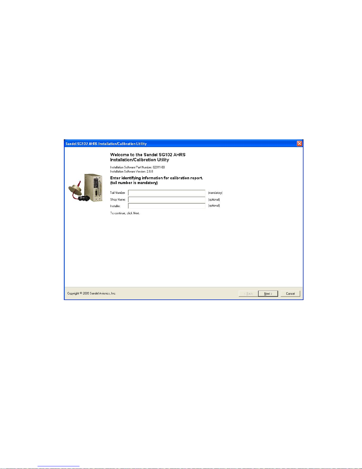
6Startup Screen................................................................................................................................ 6
6.1Enter Shop Name and Aircraft ID................................................................................................................. 6
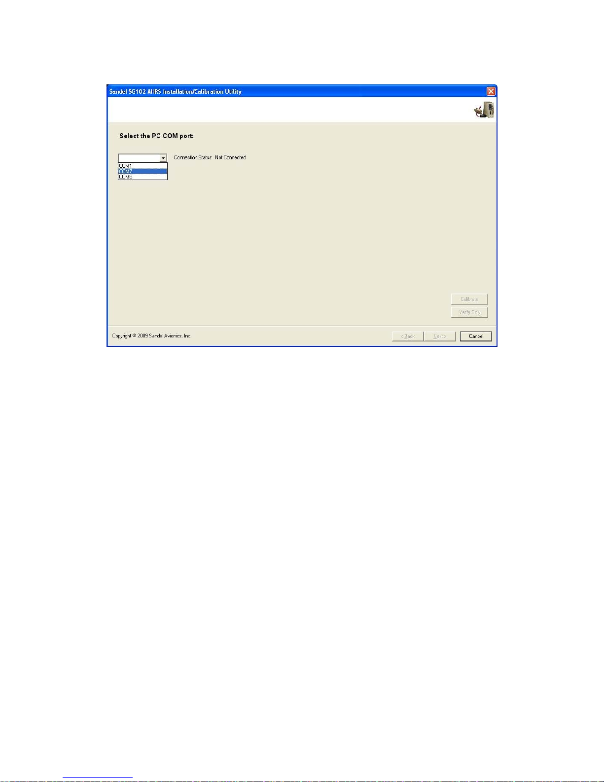
6.2SG102 Communication................................................................................................................................. 6
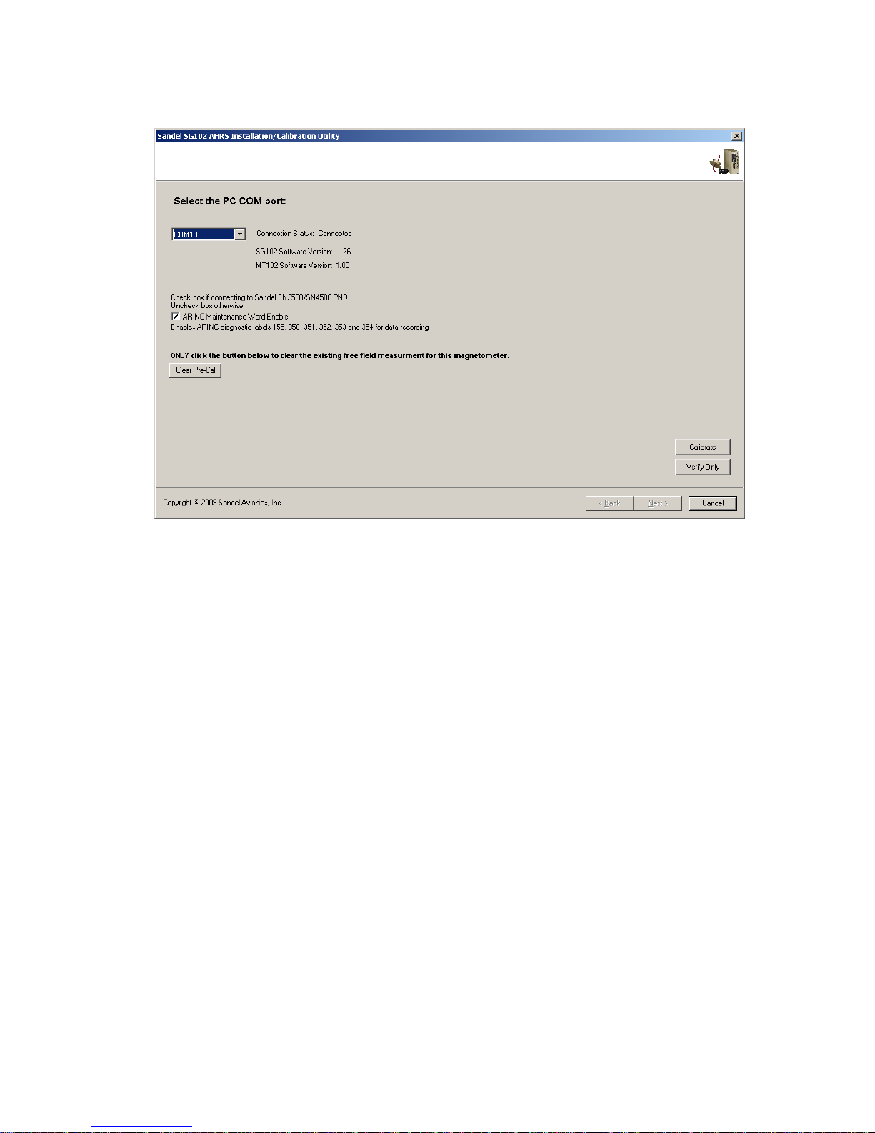
6.2.1Establish Communication ......................................................................................................... 6
6.2.2Select ARINC 429 Speed (Hardware Mod 2 and Later):.......................................................... 8
6.2.3Check ARINC Maintenance Word Enable (1.25 and later):..................................................... 9
6.2.4‘Clear Pre-Cal’ button (1.26 and later)...................................................................................... 9
6.2.5“Pre-Cal”................................................................................................................................... 9
6.2.6“Calibrate” ................................................................................................................................ 9
6.2.7“Verify Only”............................................................................................................................ 9
7Pre-Cal Procedure (MT102 Unmounted)................................................................................... 10
7.1Make the MT102 Free Field Measurement................................................................................................. 10
7.2Mount the MT102 in the aircraft................................................................................................................. 11
8Calibration.................................................................................................................................... 12
8.1Notes on Aircraft Configuration.................................................................................................................. 12
8.2Taxi to the Compass Rose........................................................................................................................... 12
8.3Perform Calibration..................................................................................................................................... 12
8.3.1Re-establish PC Communications........................................................................................... 12
8.3.2Select SG102 Mount Direction............................................................................................... 13
8.3.3Coarse Calibration (1.26 or later)............................................................................................ 14
8.3.4Fine Calibration ...................................................................................................................... 17
8.3.5Lattitude and Magvar (1.10 and earlier only).......................................................................... 18
8.3.6Create Log File ....................................................................................................................... 18
8.4Verification – Calibration Complete........................................................................................................... 20
9For Further Assistance................................................................................................................ 21

82011-ICUG Rev G SG102 AHRS Installation/Calibration Utility
3
2 Revision History
Revision Date Comments
G 09/30/2014
A/R 1572 Software was 2.70
Added “Unknown SG102 Version” error message
F 08/25/2014 A/R 1560 Software was 2.60
E 03/06/2014
A/R 1472 addition of ARINC speed selection for Mod
2 and later hardware, software version 2.60
D 03/15/2010 A/R 1112 Software was 2_30
C 11/10/2009 A/R 1098 Software was 2_20
B 9/21/2009 A/R 1092 Software was 2_00
A 7/22/2009 A/R 1071; Initial Release Version 2.0

82011-ICUG Rev G SG102 AHRS Installation/Calibration Utility
4
3 Introduction
The SG102 AHRS Installation/Calibration Utility version 2.80 and higher is a Windows
application program which runs on a laptop or PC. When used in conjunction with the
SG102 Maintenance Adapter it uses the computer’s USB port to perform the mount
position selection and compass alignment of the SG102/MT102 system after installation
in the aircraft.
The software works with all versions of SG102. Where a specific step is version-specific,
this will be noted in the instructions.
For SG102 software version 1.26 or later, this utility performs a 2-step coarse-fine
calibration. This enhancement allows improved performance when operating in more
difficult (i.e. highly magnetized) airframe environments.
For SG102 Mod 2 or later hardware with software version 1.50 or later, this utility
presents the option for ARINC 429 High Speed.
The final system calibration values are stored in a configuration module physically
located in the MT102. This calibration data is retrieved every time the SG102 system
powers up. In the event of an SG102 replacement the calibration data stays with the
aircraft and therefore realignment of the SG102 is not required.
Note: The SG102 Maintenance Adapter Windows Drivers must be installed on
the PC first. See the Maintenance Adapter User Guide.
3.1 Related Information
Description SPN
SG102 Maintenance Adapter 82132
SG102 Maintenance Adapter Users Guide 82132-UG
USB Cable 88114
SG102 Installation CD 82011-INCD
SG102 Installation/Calibration Utility 82011-ICU
MT102 Maintenance Extension Cable Drawing 88128-10
4 Installing the Software on your PC
1) On your PC, create a directory in “C:\” called SG102Install.
2) Copy SG102Install_v2_XX.exe into that directory.
3) Navigate to C:\SG102Install in Windows Explorer.
4) Create a folder called “Reports” in the C:\SG102Install folder. To do this, right-
click anywhere within the C:\SG102Install folder and select “New->Folder” from
the drop-down menu. Rename the “New Folder” to “Reports”.

82011-ICUG Rev G SG102 AHRS Installation/Calibration Utility
5
5) Right click on the SG102Install_v2_XX.exe icon and select “Create Shortcut”
from the dropdown menu.
6) Move the shortcut icon to the PC desktop.
5 Connecting the SG102 AHRS Maintenance Adapter
1) Follow the instructions in the SG102 Maintenance Adapter User Guide for
installation of the USB serial port drivers if this has not been done.
2) Ensure that the switch is in the IN (“NORMAL”) position before powering up the
SG102 for Installation/Calibration. The green LED in the switch will be OFF
when the USB connector is attached and the switch is in this position. The switch
must be in the correct position BEFORE the SG102 is powered up.
3) When the SG102 power is applied all 4 SG102 LED’s will illuminate
momentarily – then the Error LED will flash until the unit goes valid..
PROPER SG102 LED INDICATIONS
SWITCH : IN POSITION
LED OFF
LED’s ALL ON MOMENTARILY.
If only POWER LED is on, recheck the
mode pushbutton switch.

82011-ICUG Rev G SG102 AHRS Installation/Calibration Utility
6
6 Startup Screen
6.1 Enter Shop Name and Aircraft ID
Note: This information needs to be entered only on the 1st pass through the program.
1) Double click the SG102 AHRS Installation/Calibration Utility shortcut icon on
your desktop.
2) Enter the tail number of the aircraft and the shop name and installer name at the
prompts. Click the “Next >” button to continue.
6.2 SG102 Communication
6.2.1 Establish Communication
Note: This information needs to be entered only on the 1st pass through the program.
1) This screen allows selecting the PC COM port for communicating with the
SG102/MT102. If the SG102 AHRS Installation/Configuration Utility has been
run before, it will automatically select the last COM port used.
2) If communication automatically establishes, proceed to section 6.2.2.
3) If communications does not automatically establish, then manually select the
correct COM port for communicating with the SG102. If the correct port is
unknown there is no harm in trying the different options until you find the right
one.

82011-ICUG Rev G SG102 AHRS Installation/Calibration Utility
7
When the correct COM port is selected, the Connection Status changes to Connected.
If an error message “Unknown SG102 Version. Program will CANCEL...” appears,
press the OK button to close the program and contact Sandel for assistance.
After establishing the connection, software version information appears for the
SG102 and the MT102. Once connected, the following information appears:

82011-ICUG Rev G SG102 AHRS Installation/Calibration Utility
8
6.2.2 Select ARINC 429 Speed (Hardware Mod 2 and Later):
For Mod 2 hardware and later, the High speed 429 option is available and may be
selected.
Factory setting is Low speed.
Units prior to Mod 2 only support Low speed.

82011-ICUG Rev G SG102 AHRS Installation/Calibration Utility
9
6.2.3 Check ARINC Maintenance Word Enable (1.25 and later):
Note: For SG102 Software before 1.25 the ARINC checkbox does not appear.
Check this box if connected to a Sandel SN3500/SN4500 PND. This adds debugging
labels to the SN3500/4500 data recording systems.
Uncheck this box if not connected to a Sandel SN3500/SN4500 to suppress these
labels.
6.2.4 ‘Clear Pre-Cal’ button (1.26 and later)
This button is normally not used. It appears on the 2nd pass through the program after
the Pre-Cal procedure has been completed. Clicking this button will clear the previous
Free Field measurement file if it is desired to repeat the free field measurement for any
reason.
6.2.5 “Pre-Cal”
This button appears if the Pre-Cal has not yet been done. Proceeds to the Pre-Cal
procedures.
6.2.6 “Calibrate”
This button appears after Pre-Cal has been done. Proceeds to the Calibrate procedures.
6.2.7 “Verify Only”
This button is normally not used. It allows you to verify an existing calibration without
changing anything.

82011-ICUG Rev G SG102 AHRS Installation/Calibration Utility
10
7 Pre-Cal Procedure (MT102 Unmounted)
7.1 Make the MT102 Free Field Measurement
This step is performed after the SG102 is installed but prior to final mounting of
MT102. It is an off-aircraft measurement of the local magnetic field that is made using
the Maintenance Extension Cable.
Note: The MT102 may be connected/disconnected with the SG102 power on.
1) Attached the MT102 extension cable.
2) Place the MT102 on a level surface away from the aircraft, stray magnetic fields,
concrete rebar, etc. For instance, the MT102 may be placed on a board laid across
the top of a large plastic bin, cardboard box, or any suitable non magnetic surface.
The MT102 must be level at a height of approximately 3’ off the ground or
higher.
3) Click the “Execute” button.
4) After the measurement has been made, the data will be displayed.

82011-ICUG Rev G SG102 AHRS Installation/Calibration Utility
11
5) Click “Finish” to store the measurement to the PC.
6) The program will now exit.
7) The PC and SG102 may now be shut down.
7.2 Mount the MT102 in the aircraft
Disconnect the Maintenance Extension Cable and install the MT102 in its final position
in accordance with the Installation Manual.

82011-ICUG Rev G SG102 AHRS Installation/Calibration Utility
12
8 Calibration
8.1 Notes on Aircraft Configuration
All calibration steps are performed in the aircraft with the engine power and
electrical loads as indicated below to ensure the magnetic environment during
compass rose calibration matches as closely as possible the magnetic environment
during flight.
1) Ensure that the SG102 AHRS Maintenance Adaptor (PN 82132) is securely
attached to the SG102.
2) Battery Master switch should be ON.
3) Engine(s) should be running (see step 8).
4) For Helicopters, rotor must be engaged and spinning (for those with a rotor
clutch).
5) Avionics master switch ON.
6) All available avionics equipment ON. In addition, rotating beacon and strobe
lights should be ON.
7) Typical engine operation. The purpose is to ensure that test conditions are similar
to flight conditions.
Jet Engines at idle.
Turbine aircraft at 60%.
Piston aircraft at 1800 RPM.
Rotor Speed no less than 30%-40%
8.2 Taxi to the Compass Rose
Proceed to a calibrated Compass Rose or compass calibration location at least 100 feet
from large metal objects such as: fuel trucks, aircraft tugs, metal buildings, high power
lines and transformers and underground fuel tanks. A calibrated, handheld sight
compass is strongly recommended for this procedure. It is essential to align the aircraft
precisely at each calibration point.
8.3 Perform Calibration
8.3.1 Re-establish PC Communications
Start up the PC and the Installation Utility. Communications with the SG102 should re-
establish. When this occurs the MT102 Free Field measurement previously recorded
will be retrieved and the Calibrate button will proceed to the Mount Direction screen.

82011-ICUG Rev G SG102 AHRS Installation/Calibration Utility
13
8.3.2 Select SG102 Mount Direction
1) Select the mount orientation by clicking on the appropriate picture.
2) Click “Next >” to continue if mount position was not changed.

82011-ICUG Rev G SG102 AHRS Installation/Calibration Utility
14
3) If the mount position selected has changed, click “CHANGE MOUNT”.
4) Follow the on-screen instructions.
5) The program will ask for the SG102 power to be turned off.
6) After turning the power off, wait for the screen prompt before turning power back
on.
Note: After recycling the power the SG102 Status window will turn red (invalid) for
approximately 2 minutes. The approximate time to valid will show in the “warmup time”
window on the following screen. Do not move the aircraft.
8.3.3 Coarse Calibration (1.26 or later)
1) Establish the aircraft configuration and power settings previously specified.
2) Physically point the aircraft precisely to one of the cardinal headings.
3) The PC will show the MT102 reading. This is reference information only – it
will show any magnetic errors.
4) Use the compass rose or sight compass to align the aircraft.
Note: The calibration at the cardinal headings can be done in any order.

82011-ICUG Rev G SG102 AHRS Installation/Calibration Utility
15
5) Wait until the Rate Meter is in the green and then click the appropriate
“Calibrate” button .
6) The button will turn green and ‘OK’ appears in the text box.
Note: The compass pointer will not change position.

82011-ICUG Rev G SG102 AHRS Installation/Calibration Utility
16
7) Repeat the steps for the other 3 cardinal headings.
8) After successfully collecting data at the four cardinal headings, all will be green.
Click “Next >” button to proceed to Step 3 – Fine Calibration.

82011-ICUG Rev G SG102 AHRS Installation/Calibration Utility
17
8.3.4 Fine Calibration
1) Physically point the aircraft precisely to one of the cardinal headings.
2) The compass pointer on the PC will now show the MT102 readings with the
coarse calibration applied. This is reference information only – it still shows
magnetic error left after the coarse calibration.
Note: The fine calibration at the cardinal headings can be done in any
order.
3) Use the compass rose or sight compass to align the aircraft.
4) Wait until the Rate Meter indicator is in the green and click the appropriate
“Calibrate” button.
5) The button will turn green and ‘OK’ appears in the text box.
Note: The compass pointer will not change position.

82011-ICUG Rev G SG102 AHRS Installation/Calibration Utility
18
6) Repeat the steps for the other 3 cardinal headings.
7) Click “Store Configuration Module” to store the calibration data to the MT102.
Note: “Cancel” is normally not used. It provides a way to abandon all calibration
data and exit the program.
8.3.5 Lattitude and Magvar (1.10 and earlier only)
Enter the home airport Latitude and Magnetic Variation.
8.3.6 Create Log File
This step allows you to view the calibration results, and store to a log file. In the
unlikely event a printer is available it will also allow a printout to be made.
Note: The log file is a simple text file which may be printed at any time.

82011-ICUG Rev G SG102 AHRS Installation/Calibration Utility
19
1) Click “Print Report” if a printer is available.
2) Click “Next >” to store the calibration log file and proceed to the Verification
step.
3) When the “Next >” button is clicked, a file browser appears
4) Navigate to the location where you would like to store the calibration log file, and
click the “Save” button to store the calibration log.
5) Clicking “Cancel” will abandon the log file. This is not advised as a permanent
record will not be kept.
Other manuals for SG102 AHRS
1
Table of contents