Sansui HDTV2600 User manual

R
26” WIDE FLAT DIGITAL TELEVISION
HDTV2600
OWNER’S MANUAL
TV/CABLE MODE SELECTION
When shipped from the factory, the TV/CABLE menu option is set to the “CABLE” (Cable Television)
mode. If not using Cable TV, set this menu option to the “TV” position.
Before operating the unit, please read this manual thoroughly.
ATTENTION
If you purchase a universal remote control from your local retailer, please contact the remote
manufacturer for the required programming code.
IF CONTACT WITH CUSTOMER SERVICE IS REQUIRED
PLEASE HAVE THE MODEL NUMBER READY PRIOR TO THE CALL
CUSTOMER SERVICE – 1-800-289-0980
ORION WEBSITE
FOR INFORMATION ON OUR OTHER PRODUCTS, PLEASE VISIT OUR WEBSITE AT
www.orionsalesinc.com
3R90101C_En_cover 4/25/05, 7:33 PM1

2
The lightning flash with arrowhead symbol, within an equilateral triangle
is intended to alert the user to the presence of uninsulated dangerous
voltage within the product's enclosure that may be of sufficient
magnitude to constitute a risk of electric shock.
The exclamation point within an equilateral triangle is intended to alert
the user to the presence of important operating and maintenance
(servicing) instructions in the literature accompanying the appliance.
CAUTION:
TO REDUCE THE RISK OF
ELECTRIC
SHOCK, DO NOT REMOVE
COVER
(OR BACK). NO USER-SERVICEABLE
PARTS INSIDE. REFER SERVICING
TO
QUALIFIED SERVICE PERSONNEL.
CAUTION: Changes or modifications not expressly approved by the party responsible for compliance with the FCC
Rules could void the user's authority to operate this equipment.
1. READ INSTRUCTIONS
All the safety and operating instructions should be read before the unit is operated.
2. RETAIN INSTRUCTIONS
The safety and operating instructions should be retained for future reference.
3. HEED WARNINGS
All warnings on the unit and in the operating instructions should be adhered to.
4. FOLLOW INSTRUCTIONS
All operating and use instructions should be followed.
5. CLEANING
Unplug this unit from the wall outlet before cleaning. Do not use liquid cleaners or aerosol cleaners. Use a damp cloth for
cleaning the exterior cabinet only.
6. ATTACHMENTS
The manufacturer of this unit does not make any recommendations for attachments, as they may cause hazards.
7. WATER AND MOISTURE
Do not use this unit near water. For example, near a bathtub, washbowl, kitchen sink, laundry tub, in a wet basement, or
near a swimming pool.
8. ACCESSORIES
Do not place this unit on an unstable cart, stand, tripod, bracket, or table.
The unit may fall, causing serious injury, and serious damage to the unit.
8A. An appliance and cart combination should be moved with care. Quick stops, excessive
force, and uneven surfaces may cause the appliance and cart combination to overturn.
9. VENTILATION
Slots and openings in the cabinet back or bottom are provided for ventilation, to ensure reliable operation of the unit and
to protect it from overheating. These openings must not be blocked or covered. The openings should never be blocked by
placing the unit on a bed, sofa, rug, or other similar surface. This unit should never be placed near or over a radiator or
heat source. This unit should not be placed in a built-in installation, such as a bookcase, or rack unless proper ventilation
is provided or the manufacturer's instructions have been adhered to.
10. POWER SOURCE
This unit should be operated only from the type of power source indicated on the rating plate. If you are not sure of the
type of power supply to your home, consult your appliance dealer or local power company. For units intended to operate
from battery power, or other sources, refer to the operating instructions.
11. GROUNDING OR POLARIZATION
This unit is equipped with a polarized alternating current line plug (a plug having one blade wider than the other). This
plug will fit into the power outlet only one way. This is a safety feature. If you are unable to insert the plug fully into the
outlet, try reversing the plug. If the plug should still fail to fit, contact your electrician to replace your obsolete outlet. Do
not defeat the safety purpose of the polarized plug. If your unit is equipped with a 3-wire grounding-type plug, a plug
having a third (grounding) pin, this plug will only fit into a grounding-type power outlet. This too, is a safety feature. If you
are unable to insert the plug into the outlet, contact your electrician to replace your obsolete outlet. Do not defeat the safety
purpose of the grounding-type plug.
12. POWER-CORD PROTECTION
Power-supply cords should be routed so that they are not likely to be walked on or pinched by items placed upon or
against them, paying particular attention to cords at plugs, convenience receptacles, and the point where they exit from
the appliance.
WARNING: TO PREVENT FIRE OR SHOCK HAZARD, DO NOT EXPOSE THIS APPLIANCE TO RAIN OR
MOISTURE.
S3126A
PORTABLE CART WARNING
(symbol provided by RETAC)
IMPORTANT SAFEGUARDS
3R90101c_En_p02-09 4/25/05, 7:33 PM2

3
GROUND CLAMP
ELECTRIC
SERVICE
EQUIPMENT
ANTENNA LEAD IN WIRE
ANTENNA DISCHARGE UNIT
(NEC SECTION 810-20)
GROUNDING CONDUCTORS
(NEC SECTION 810-21)
POWER SERVICE GROUNDING ELECTRODE SYSTEM
(NEC ART 250, PART H)
NEC-NATIONAL ELECTRICAL CODE
GROUND CLAMPS
S2898A
13. LIGHTNING
To protect your unit during a lightning storm, or when it is left unattended and unused for long periods of time, unplug it
from the wall outlet and disconnect the antenna or cable system. This will prevent damage to the unit due to lightning and
power line surges.
14. POWER LINES
An outside antenna system should not be located in the vicinity of overhead power lines, other electric light or power
circuits, or where it can fall into such power lines or circuits. When installing an outside antenna system, extreme care
should be taken to keep from touching such power lines or circuits as contact with them might be fatal.
15. OVERLOADING
Do not overload wall outlets and extension cords as this can result in a risk of fire or electric shock.
16. OBJECT AND LIQUID ENTRY
Do not push objects through any openings in this unit as they may touch dangerous voltage points or short out parts that
could result in fire or electric shock. Never spill or spray any type of liquid into the unit.
17. OUTDOOR ANTENNA GROUNDING
If an outside antenna or cable system is connected to the unit, be sure the antenna or cable system is grounded to provide
some protection against voltage surges and built-up static charges. Section 810 of the National Electrical Code, ANSI/
NFPA 70, provides information with respect to proper grounding of the mast and supporting structure, grounding of the
lead-in wire to an antenna discharge unit, size of grounding conductors, location of antenna discharge unit, connection to
grounding electrodes, and requirements for the grounding electrode.
18. SERVICING
Do not attempt to service this unit yourself as opening or removing covers may expose you to dangerous voltage or other
hazards. Refer all servicing to qualified service personnel.
19. DAMAGE REQUIRING SERVICE
Unplug this unit from the wall outlet and refer servicing to qualified service personnel under the following conditions:
a. When the power-supply cord or plug is damaged.
b. If liquid has been spilled, or objects have fallen into the unit.
c. If the unit has been exposed to rain or water.
d. If the unit does not operate normally by following the operating instructions. Adjust only those controls that are
covered by the operating instructions, as an improper adjustment of other controls may result in damage and will
often require extensive work by a qualified technician to restore the unit to its normal operation.
e. If the unit has been dropped or the cabinet has been damaged.
f. When the unit exhibits a distinct change in performance, this indicates a need for service.
20. REPLACEMENT PARTS
When replacement parts are required, be sure the service technician uses replacement parts specified by the manufacturer
or those that have the same characteristics as the original part.
Unauthorized substitutions may result in fire, electric shock or other hazards.
21. SAFETY CHECK
Upon completion of any service or repairs to this unit, ask the service technician to perform safety checks to determine that
the unit is in proper operating condition.
22. HEAT
The product should be situated away from heat sources such as radiators, heat registers, stoves, or other products
(including amplifiers) that produce heat.
23. NOTE TO CATV SYSTEM INSTALLER
This reminder is provided to call the CATV system installer's attention to Article 820-40 of the NEC that provides guidelines
for proper grounding and, in particular, specifies that the cable ground shall be connected to the grounding system of the
building, as close to the point of cable entry as practical.
EXAMPLE OF ANTENNA GROUNDING AS PER NATIONAL ELECTRICAL CODE
3R90101c_En_p02-09 4/25/05, 7:33 PM3

4
Troubleshooting ......................................................................... 43
Specifications ............................................................................. 44
LIMITED WARRANTY ............................................................... 45
TV operation............................................................................... 20
Setting the V-Chip ...................................................................... 22
Setting the front panel lock......................................................... 25
Labeling channels ...................................................................... 26
Labeling the video input source ................................................. 27
Setting the clock ......................................................................... 28
Setting the on timer .................................................................... 29
Setting the off timer .................................................................... 30
Setting the picture size ............................................................... 31
Setting the picture scroll ............................................................. 33
Adjusting the picture preference ................................................ 34
Picture control adjustment.......................................................... 35
Selecting the color temperature ................................................. 36
Selecting the Scan Velocity Modulation (SVM) .......................... 36
Resetting your picture adjustment.............................................. 36
Closed Caption........................................................................... 37
CC advanced ............................................................................. 38
Selecting stereo ......................................................................... 39
Second Audio Program (SAP) ................................................... 39
Sound control adjustment .......................................................... 39
Selecting the BBE ...................................................................... 40
Selecting the digital output ......................................................... 40
Selecting the audio language ..................................................... 41
Resetting your audio adjustment................................................ 41
Checking the Digital-signal strength........................................... 42
IMPORTANT SAFEGUARDS ...................................................... 2
Contents ....................................................................................... 4
Features ....................................................................................... 5
Power source ............................................................................... 5
Parts and functions ...................................................................... 6
Remote control ............................................................................. 7
Antenna connections.................................................................... 8
Cable TV connections .................................................................. 9
Connections to other equipment ................................................ 10
Starting setup ............................................................................. 15
Setting the language .................................................................. 16
Memorizing channels ................................................................. 17
Setting your favorite channels .................................................... 19
PREPARATIONS
OTHERS
OPERATION
Contents
3R90101c_En_p02-09 4/25/05, 7:33 PM4

5
Features
High Quality Picture Horizontal Resolution More than 500 lines. It exceeds Super VHS (400 lines) or Laser
Disc (430 lines) in resolution.
Compatible with a wide range of audio outputs Digital Audio Jack (Coaxial) - When a component with a built-
in Dolby Digital decoder is connected, Dolby Digital sound can produce the effect of being in a movie theater or a
concert hall.
•Integrated Digital Tuner - You can view a digital broadcasting without using Digital TV Set-Top Box.
•Closed Caption Decoder With Full Text Mode - Displays text captions or full screen text on the screen for
hearing impaired viewers.
•Picture Adjustments Using The Remote Control - The On-Screen display allows precise remote control
adjustment of BRIGHTNESS, CONTRAST, COLOR, TINT and SHARPNESS.
•Programmable TV Sleep Timer - Operable from the remote control, the TV can be programmed up to 120
minutes to turn off automatically.
•V-Chip - The V-Chip function can read the rating of a TV program or movie content if the program is encoded
with this information. V-chip will allow you to set a restriction level.
•Stereo/SAP Reception - This TV is designed to receive stereo and second audio program (SAP) broadcasts
where available.
•BBE - BBE gives you vivid sound with incredible presence.
•2 sets of S-Video/Component Video jacks - A VCR, DVD player, satellite receiver or other audio/video
component can be connected to this unit.
•Video Input Jacks - This unit is equipped 3 types of video input jacks. The component video in jacks and
S-video in jack enable you to watch the DVD player or the video devices with high quality picture.
•On-Screen 3 Language Display - You can select one of 3 languages, English, Spanish or French for on-
screen programming.
*Manufactured under license from Dolby Laboratories. “Dolby” and the double-D symbol are trademarks of
Dolby Laboratories.
TO USE AC POWER SOURCE
Use the AC polarized line cord provided for operation on AC. Insert
the AC cord plug into a standard 120V 60Hz polarized AC outlet.
NOTES:
•Never connect the AC line cord plug to other than the specified
voltage (120V 60Hz). Use the attached power cord only.
•If the polarized AC cord does not fit into a non-polarized AC
outlet, do not attempt to file or cut the blade. It is the user’s
responsibility to have an electrician replace the obsolete outlet.
•If you cause a static discharge when touching the unit and the
unit fails to function, simply unplug the unit from the AC outlet
and plug it back in. The unit should return to normal operation.
Polarized AC Cord Plug
(One blade is wider than the other.)
AC Outlet
Wider Hole
and Blade
Power source
3R90101c_En_p02-09 4/25/05, 7:33 PM5

6
Parts and functions
Front
Rear
AC power cord
RF IN (VHF/UHF) jack
COAXIAL DIGITAL AUDIO OUT jack
S-VIDEO 1 IN jack
S-VIDEO 2 IN jack
AUDIO (L/R)/VIDEO OUT jacks
COMPONENT2 IN jacks
COMPONENT1 IN jacks
*VOLUME
▲/▼
buttons
POWER button
*CHANNEL ▲/▼buttons
POWER indicator
Remote sensor
AUDIO (L/R)/VIDEO IN jacks (VIDEO3)
AUDIO (L/R)/VIDEO IN jacks
(VIDEO1)
AUDIO (L/R)/VIDEO IN jacks
(VIDEO2)
*To display the menu screen.
Press both
VOLUME
▲/▼
buttons
at the same time to display the menu screen.
CHANNEL ▲/▼buttons and
VOLUME
▲/▼
buttons can be used to select the desired setting during the menu
screen operations.
3R90101c_En_p02-09 4/25/05, 7:33 PM6

7
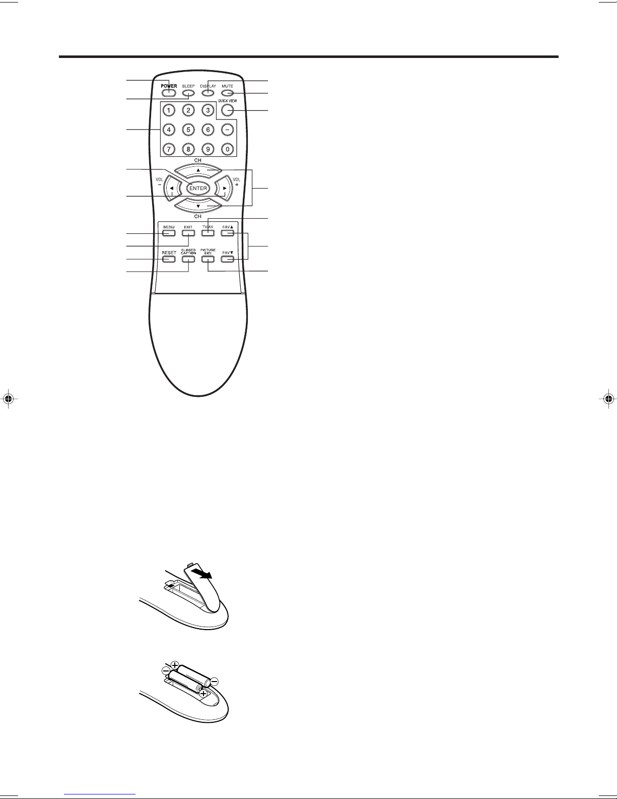
1. Open the battery compartment cover.
2. Install two “AAA” batteries (not supplied).
HOW TO INSTALL BATTERIES
Before using the remote control, batteries must first be installed.
BATTERY PRECAUTIONS
These precautions should be followed when using batteries
in this device:
•Use only the size and type of batteries specified.
•Be sure to follow the correct polarity when installing the
batteries as indicated in the battery compartment.
Reversed batteries may cause damage to the device.
•Do not mix different types of batteries together (e.g.
Alkaline and Carbon-zinc) or old batteries with fresh ones.
•If the device is not to be used for a long period of time,
remove the batteries to prevent damage or injury from
possible battery leakage.
•Do not try to recharge batteries not intended to be re-
charged; they can overheat and rupture (follow battery
manufacturer's directions).
Use two “AAA” size batteries. The batteries may last
approximately one year depending on how much the remote
control is used. For best performance, it is recommended
that batteries should be replaced on a yearly basis, or when
the remote operation becomes erratic. Do not mix old and
new batteries or different types.
Remote control
1
2
4
5
6
7
8
9
3
10
11
13
14
15
16
12
3. Replace the battery compartment cover.
4. ENTER button - Press to enter or select information for
menu screen operations.
5. VOL (VOLUME) + / – buttons - Press the +button to
increase, or the –button to decrease the volume level.
Use to select the desired setting during the menu
screen operation.
6. MENU button - Press to display the menu screen
function.
7. EXIT button - Press to exit from the menu screen.
8. RESET button - Press to reset the menu screen
picture and sound adjustments to their factory preset
positions, while in the adjustment menu.
9.
CLOSED CAPTION button - Press this button to
display CLOSED CAPTION menu
.
10. DISPLAY button - When TV receives an analog signal
and press this button, the current information will
appear in the screen. When TV receives a digital signal,
press once, the digital information will appear. Press
twice, the analog information will appear. To remove
display from the screen, press again.
11. MUTE button - To turn off the sound, press this button
once. The TV will be silenced and the symbol “MUTE”
will appear on the screen. The muting feature can be
released by pressing the MUTE button again or one of
the VOL +or –buttons.
12.
QUICK VIEW button - This button allows you to go back
to the previous channel selected by pressing the
QUICK VIEW button. Press this button again to return
to the channel you were watching.
13.
CH (CHANNEL)
▲ /▼
buttons - Press the
▲
button
to
change to a higher numbered channel set into
memory. Press the ▼button to change to a lower
numbered channel set into memory.
Use to select the desired setting during the menu
screen operation.
14. TV/AV button -
Press this button to display SOURCE
SELECTION menu to select the video input source
.
15. FAV ▲ /▼ buttons - Press to select your favorite
channels.
16. PICTURE SIZE button -
Press this button to display
PICTURE SIZE
menu
.
1. POWER button - Press to turn the TV on. Press
again to turn the TV off.
2. SLEEP button - To set the TV to turn off after a
preset amount of time, press this button.
3. Direct Channel Selection buttons (0-9) - Allows
direct access to any channel. The “–” button is
used to select digital channels.
3R90101c_En_p02-09 4/25/05, 7:33 PM7

8
If you are using an indoor or outdoor antenna, follow the instructions below that correspond to your antenna
system. If you are using a cable TV service (CABLE), see page 9 for Cable TV connections.
Combination VHF/UHF Antenna (Separate VHF and UHF 300 ohm Twin-lead Wires)
Combination VHF/UHF Antenna (Single 75 ohm Cable or 300 ohm Twin-lead Wire)
Antenna connections
75 ohm
Coaxial
Cable 300-75 ohm
Matching
Transformer
300-75 ohm
Matching
Transformer
UHF 300 ohm
VHF 300 ohm
UHF 300 ohm
VHF 75 ohm
Separate VHF/UHF Antennas (75 ohm VHF Cable and 300 ohm UHF Twin-lead Wires)
RF IN
jack RF IN
jack
RF IN
jack
Combiner
RF IN
jack
Combiner
Connect the 75 ohm Cable from the Combination
VHF/UHF Antenna to the RF IN Jack.
If your Combination VHF/UHF Antenna has a 300
ohm Twin-lead Wire, the use of the 300-75 ohm
Matching Transformer may be necessary.
Connect the UHF 300 ohm Twin-lead Wire to the
Combiner (not supplied). Connect the VHF 300
ohm Twin-lead Wire to the 300-75 ohm Matching
Transformer. Attach the Transformer to the Com-
biner, then attach the Combiner to the RF IN Jack.
Connect the VHF 75 ohm cable and UHF 300 ohm
Twin-lead Wire to the Combiner. Attach the Com-
biner to the RF IN Jack.
3R90101c_En_p02-09 4/25/05, 7:33 PM8

9
FOR SUBSCRIBERS TO BASIC CABLE TV SERVICE
For basic cable service not requiring a Converter/Descrambler
box, connect the 75 ohm Coaxial Cable directly to the RF IN
Jack on the back of the unit.
Cable TV connections
FOR SUBSCRIBERS TO SCRAMBLED CABLE TV SERVICE
75 ohm
Coaxial Cable
If you subscribe to a Cable TV service in which basic channels are unscrambled and premium channels require the
use of a Converter/Descrambler box, you may wish to use a signal Splitter and an A/B Switch box (available from
the Cable TV company or an electronics supply store). Follow the connections shown below. With the switch in the
“B” position, you can directly tune any nonscrambled channels on your unit. With the switch in the “A” position, tune
your unit to the output of the Converter/Descrambler box (usually channel 3 or 4) and use the Converter/Descrambler
box to tune scrambled channels.
Splitter B
A
Incoming 75 ohm
CABLE TV Cable A/B Switch
75 ohm Cable
to unit
Incoming 75 ohm
CABLE TV Cable 75 ohm Cable to unit
Converter/
Descrambler
RF IN
jack
RF IN
jack
RF IN
jack
Converter/
Descrambler
This unit has an extended tuning range and can tune most cable channels without using a Cable TV
Converter box. Some Cable TV companies offer “premium pay channels” in which the signal is
scrambled. Descrambling these signals for normal viewing requires the use of a descrambler device
which is generally provided by the Cable TV company.
If you subscribe to a Cable TV service which requires the use of a Converter/Descrambler box, connect the
incoming 75 ohm Coaxial Cable to the Converter/Descrambler box. Using another 75 ohm Coaxial Cable,
connect the output jack of the Converter/Descrambler box to the RF IN Jack on the unit. Follow the connections
shown below. Set the unit to the output channel of the Converter/Descrambler box (usually channel 3 or 4) and
use the Converter/Descrambler box to select channels.
FOR SUBSCRIBERS TO UNSCRAMBLED BASIC CABLE TV SERVICE WITH
SCRAMBLED PREMIUM CHANNELS
3R90101c_En_p02-09 4/25/05, 7:33 PM9

10
Connections to other equipment
The exact arrangement you use to interconnect various video and audio components to the TV is dependent on
the model and features of each component. Check the Owner's Manual provided with each component for the
location of video and audio inputs and outputs.
The connection diagrams below are offered as suggestions. You may need to modify them to accommodate
your particular assortment of components. The diagrams are intended to show component video and audio
interconnections only.
Pressing TV/AV on the remote control displays the current signal source
(press TV/AV again or 0-5to change).
Selecting the video input source
Press TV/AV to view a signal from another device connected to your TV, such
as a VCR or DVD player. You can select ANT, VIDEO1, VIDEO2, VIDEO3 (on
the front panel), COMPONENT1, or COMPONENT2 depending on which
input jacks you used to connect your devices.
SOURCE SELECTION
0. ANT
1. VIDEO1
2. VIDEO2
3. VIDEO3
4. COMPONENT1
5. COMPONENT2
SELECT : /0-5
SET: ENTER
To connect the TV to a VCR with an S-Video cord
If you connect a VCR with a S-VIDEO cord to the S-VIDEO IN jack on the rear of the TV, you must also connect
the audio cords to the AUDIO IN jacks on the rear of the TV. The S-VIDEO cord only carries the video signal.
The audio signal is separate.
NOTE:
When the S-video cord and the video cord are connected to each jack at the
same time, the S-video cord takes precedence over the video cord.
Rear of the TV
To S-Video OUT
To Audio OUT
Audio cord (not supplied)
S-Video cord (not supplied)
To S-VIDEO IN 1 (or 2)
To connect the TV to a VCR
Rear of the TV
To Audio/Video OUT
Audio/Video cord (not supplied)
To AUDIO/VIDEO IN 1 (or 2)
To AUDIO IN 1 (or 2)
3R90101C_En_p10-14 4/25/05, 7:33 PM10

11
To connect the TV to a DVD player/Satellite receiver
If your DVD player or Satellite receiver has a S-Video out jack, connect cords as shown.
Rear of the TV
To S-Video OUT
Audio cord (not supplied)
To Audio OUT
S-Video cord (not supplied)
To S-VIDEO IN 1 (or 2)
YP
B
P
R
To connect the TV to a DVD player with component video
If your DVD player has component video out jacks, connect your TV to a DVD player using a component video
cord. It can greatly enhance picture quality and performance.
Rear of the TV
To Component OUTTo Audio OUT
Audio cord (not supplied)
Video cord (not supplied)
To AUDIO IN 1 (or 2)
To COMPONENT IN 1 (or 2)
NOTE:
Component Video input of this unit are for use of device which output 480i/1080i interlaced signals and 480p/
720p progressive signals.
Connections to other equipment (continued)
3R90101C_En_p10-14 4/25/05, 7:33 PM11

12
Connections to other equipment (continued)
To connect the TV to a DTV receiver/set-top box
If you connect a DTV receiver/set-top box, connect your TV to a DTV receiver/set-top box using a component
video cord.
Rear of the TV
To Component OUTTo Audio OUT
Audio cord (not supplied)
Video cord (not supplied)
YP
B
P
R
To COMPONENT IN 1 (or 2)
3R90101C_En_p10-14 4/25/05, 7:33 PM12

13
Using an Audio Amplifier
Using an AV Amplifier with built-in digital surround
If you are using an Amplifier with built-in digital surround sound as follows, you can enjoy various audio systems
including Dolby Digital Surround audio that sounds just like the movie.
Connect an AV amplifier with built-in Dolby Digital decoder, or etc as shown below.
To Audio (L) Input To Audio (R) Input
Audio cord (not supplied)
Amplifier
Rear of the TV
AUDIO (R) OUTPUT
AUDIO (L) OUTPUT
NOTE:
When you make the connection above, on the AV Amplifier, do not set DOLBY DIGITAL to DOLBY DIGITAL,
or MPEG to MPEG “ON”. If you do, a loud noise will emit from the speakers possibly causing damage to your
hearing or to the speakers.
Coaxial digital cable
(not supplied)
AV Amplifier with built-in digital surround
decoder as listed above
Center Speaker
Front
Speaker
(Left)
Front
Speaker
(Right)
Subwoofer
Surround
Speaker (Left) Surround
Speaker
(Right)
COAXIAL DIGITAL
AUDIO OUTPUT
To Coaxial Digital
Audio Input
Rear of the TV
TV
*Manufactured under license from Dolby Laboratories. “Dolby” and the double-D symbol are trademarks of Dolby
Laboratories.
Connections to other equipment (continued)
3R90101C_En_p10-14 4/25/05, 7:33 PM13

14
TV GAME
To connect the TV to a camcorder
To connect the TV to a Game
The TV can also be used as a display device for many video games. However, due to the wide variety of signals
generated by these devices and subsequent hook-up variations required, they have not all been included in the
suggested connection diagrams. You'll need to consult each component's Owner's Manual for additional
information.
To playback from a camcorder, connect the camcorder to the TV as shown.
Front of the TV
Audio/Video cord (not supplied)
To Audio/Video OUT
Front of the TV
To Audio/Video OUT
Audio/Video cord (not supplied)
Connections to other equipment (continued)
3R90101C_En_p10-14 4/25/05, 7:33 PM14

15
Starting setup
4
2
3Press ▲or ▼to select
“START”, then press ENTER.
If you select “CANCEL” and
press ENTER, the
STARTING SETUP stops
and changes to the TV
screen.
1Press POWER. The starting
setup function begins and
the Language setup menu
appears on the screen.
Press ▲or ▼ to select your
desired language, then press
ENTER.
IMPORTANT: Make sure that the antenna or cable TV system
connection is made!
Press ▲or ▼to select “TV”
or “CABLE”, then press
ENTER.
The STARTING SETUP menu appears
the first time you turn on the TV, and
helps you select the menu language,
specify the TV/CABLE setting, and
program channels automatically.
•
When you make a menu selection, your changes occur immediately.
You do not have to press EXIT to see your changes.
•When you are finished programming the menus, press EXIT.
NOTE:
If you press EXIT in the process of “AUTO SETUP”, the STARTING
SETUP stops and changes to the normal screen.
:SELECT SET :ENTER
LANGUAGE / LANGUE / IDIOMA
ENGLISH
FRANÇAIS
ESPAÑOL
:SELECT SET :ENTER
CHANNEL PLAN
TV
CABLE
:SELECT SET :ENTER
AUTO SETUP
START
CANCEL
Now the “AUTO SETUP” starts. After the starting setup is com-
pleted, the TV channel appears on the screen.
•It may take up to 30 minutes to complete memorizing digital
cable channels, please be patient.
3R90101C_En_p15-18 4/25/05, 7:33 PM15

16
3
Then press or to select
SETUP menu.
Press or to select the desired language: English (ENGLISH),
French (FRANÇAIS) or Spanish (ESPAÑOL).
1
2
Press ▲or ▼to select
“LANGUAGE”.
4
Press EXIT to return to the normal screen.
SETUP
LANGUAGE ENGLISH
ENGLISH /FRANÇAIS / ESPAÑOL
CLOCK SET 12:00 AM
TV/CABLE CABLE
AUTO CH MEMORY
ADD/DELETE
:SELECT :ADJUST
Press MENU. The menu screen will appear.
5
Setting the language
You can choose from three different
languages (English, French and
Spanish) for the on-screen displays.
NOTE:
If no buttons are pressed for more than
15 seconds, the MENU screen will re-
turn to normal TV-operation automati-
cally.
3R90101C_En_p15-18 4/25/05, 7:33 PM16

17
Press MENU. The menu screen will appear.
Press or to select
SETUP menu.
This TV is equipped with a channel memory feature which allows channels to skip up or down to the next
channel set into memory, skipping over unwanted channels. Before selecting channels, they must be pro-
grammed into the TV’s memory. This TV can receive up to 250 VHF/UHF channels and 500 cable TV channels.
To use this TV with an antenna, set the TV/CABLE menu option to the TV mode. When shipped from the factory,
this menu option is in the CABLE mode.
TV/CABLE selection
Press or to select “TV” or
“CABLE”.
Press EXIT to return to the normal screen.
Press ▲or ▼to select
“TV/CABLE”.
TV -VHF/UHF channels
CABLE -CABLE TV channels
1
2
3
4
5
CABLE CHART
The chart below is typical of many cable system channel allocations.
Memorizing channels
3R90101C_En_p15-18 4/25/05, 7:33 PM17

18
Press MENU. The menu screen will appear.
Press or to select SETUP
menu, then press ▲or ▼to
select “AUTO CH MEMORY”.
Automatic memory tuning
Press EXIT to return to the normal screen.
1
2
3
To add/delete channels
4
AUTO CH MEMORY
CANCEL : EXIT
PROGRAMMING NOW
PLEASE WAIT
Press or to select SETUP
menu, then press ▲or ▼to
select “ADD/DELETE”.
Press or . The ADD/DELETE
menu will appear.
2
ADD / DELETE
ADD / DELETE
CH SIGNAL
1 ANALOG DELETE
2 ANALOG ADD
3 ANALOG DELETE
4 ANALOG DELETE
5 ANALOG ADD
5-001 DIGITAL ADD
5-002 DIGITAL ADD
CLEAR ALL
SETUP MENU
:SELECT :ADJUST
3Press ▲or ▼ to select
“ADD/DELETE”, then press .
ADD/DELETE
ADD/DELETE
CH SIGNAL
1ANALOG ADD/DELETE
2 ANALOG ADD
3 ANALOG DELETE
4 ANALOG DELETE
5 ANALOG ADD
5-001 DIGITAL ADD
5-002 DIGITAL ADD
CLEAR ALL
SETUP MENU
:SELECT :ADJUST
4Select the desired channel to
be memorized or deleted using
▲or ▼.
Press or to select “ADD” or
“DELETE”, whichever function
you want to perform.
5Repeat step 4 for other channels you want to add or delete, then
press ENTER.
CLEAR ALL
All channels are deleted from the channel memory.
Press ▲or ▼to select “CLEAR ALL” in step 2 above, then press
or .
Memorizing channels (continued)
Press MENU. The menu screen will appear.
1
6Press EXIT to return to the normal screen.
NOTE:
Some new channels may be appeared.
So, it is recommended to do the “AUTO
CH MEMORY” procedure periodically.
Press or . The TV will begin
memorizing all the channels
available in your area.
•It may take up to 30 minutes
to complete memorizing
digital cable channels, please
be patient.
3R90101C_En_p15-18 4/25/05, 7:33 PM18

19
4
Setting your favorite channels
Press or to select “SET” and
press ENTER.
2
3Press ▲or ▼to select
“FAVORITE CH”, then press
or . The FAVORITE CH
menu will appear.
NOTES:
•You can still use CH ▲or ▼to
scan through all the channels you
programmed in the TV’s memory.
•FAV ▲or ▼ will not work until you
have programmed your favorite
channels.
1Select a channel you wish to include in your favorite channel list.
5
6
Press EXIT to return to the
normal TV screen.
Setting your favorite channels
Press MENU, then press or
to select OPTION menu.
You can preset up to 12 of your
favorite channels.
Repeat steps 1-5 for up to 11 additional channels.
To watch your favorite channels
Press FAV ▲or ▼ on the remote control to select your favorite
channels.
To delete your favorite channels
1Select a channel you want to remove from favorite channels.
2Press MENU, then press or
to select OPTION menu.
Press ▲or ▼to select
“FAVORITE CH”, then press
or to display the FAVORITE
CH menu.
3Press or to select “CLEAR”
and press ENTER.
4Press EXIT to return to the normal screen.
OPTION
ON/OFF TIMER OFF
FAVORITE CH
CH LABEL
VIDEO LABEL
:SELECT :ADJUST
OPTION
ON/OFF TIMER OFF
FAVORITE CH
CH LABEL
VIDEO LABEL
:SELECT :ADJUST
FAVORITE CH:CH 23-100
SET/CLEAR TV CABLE
123-456 15-001 6-001
13 23-100 0
0 0 0
0 0 0
OPTION MENU
:SELECT :ADJUST
CLEAR:ENTER END :EXIT
OPTION
ON/OFF TIMER OFF
FAVORITE CH
CH LABEL
VIDEO LABEL
:SELECT :ADJUST
3R90101C_En_p19-24 4/25/05, 7:33 PM19

20
VOLUME 32
TV operation
If a channel with no broadcast is
selected, the sound will automati-
cally be muted.
If a station being viewed stops
broadcasting, the TV will automati-
cally shut itself off after 15 minutes.
To turn on the TV, press POWER.
Set the TV/CABLE menu
option to the appropriate
position (see page 17).
Adjust the volume level by pressing
VOL + or – . The volume level will
be indicated on the screen by
green bars. As the volume level
increases, so do the number of
bars. If the volume decreases, the
number of green bars also de-
creases.
1
2
3
4
Press the Direct Channel Selection
buttons to select the channel.
TO SELECT ANALOG CHANNELS
1-9: Press 0twice, then 1-9 as
needed. Example, to select
channel 2, press 0 0 2.
10-99: Press 0, then the remaining 2 digits. Example, to se-
lect channel 12, press 0 1 2.
100-125: Press the 3 digits in order. Example, to select channel
120, press 1 2 0.
TO SELECT DIGITAL CHANNELS
Press the first 3 digits, then press “–”, followed by the remaining
3 digits.
Example, to select channel 015-001, press 0 1 5 – 0 0 1.
VHF/UHF/CABLE CHANNELS
NOTES:
•
•
TV CABLE
VHF
2-13
UHF
14-69
VHF
2-13
STD/HRC/IRC
14-36 (A) (W)
37-59 (AA) (WW)
60-85 (AAA) (ZZZ)
86-94 (86) (94)
95-99 (A-5) (A-1)
100-125 (100) (125)
01 (5A)
TV -VHF/UHF channels
CABLE -CABLE TV channels
ANT
ABCD
12
3R90101C_En_p19-24 4/25/05, 7:34 PM20
Table of contents
Other Sansui TV manuals

Sansui
Sansui SLEDVD226 User manual

Sansui
Sansui DTV2760A User manual

Sansui
Sansui DTV2700 User manual

Sansui
Sansui DTV2760A User manual

Sansui
Sansui DTV1300 User guide

Sansui
Sansui HDTV3000 User manual

Sansui
Sansui SATVOMV01 User manual

Sansui
Sansui DTV1900 User manual

Sansui
Sansui SMX24Z1SMB User manual

Sansui
Sansui DFTV270 User manual

Sansui
Sansui DTV3200 User manual

Sansui
Sansui DTV2750A User manual

Sansui
Sansui HDLCD2600A User manual

Sansui
Sansui DTV2798A User manual

Sansui
Sansui HDLCD3200C User manual

Sansui
Sansui DTV3200A User manual

Sansui
Sansui DTV3250 User manual

Sansui
Sansui HDLCD3200C User manual

Sansui
Sansui DTV1900 User guide

Sansui
Sansui SV3215 LCD User manual