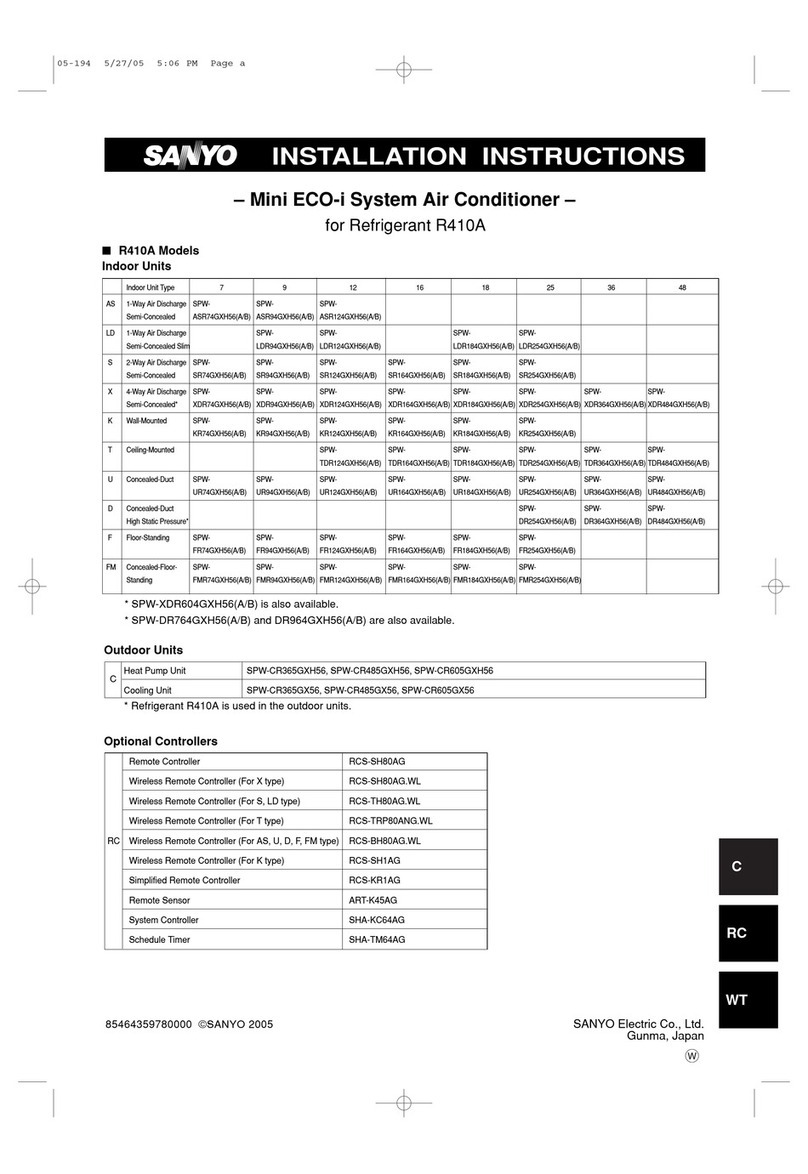
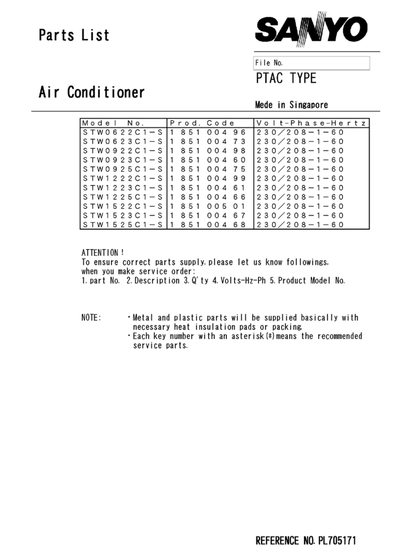
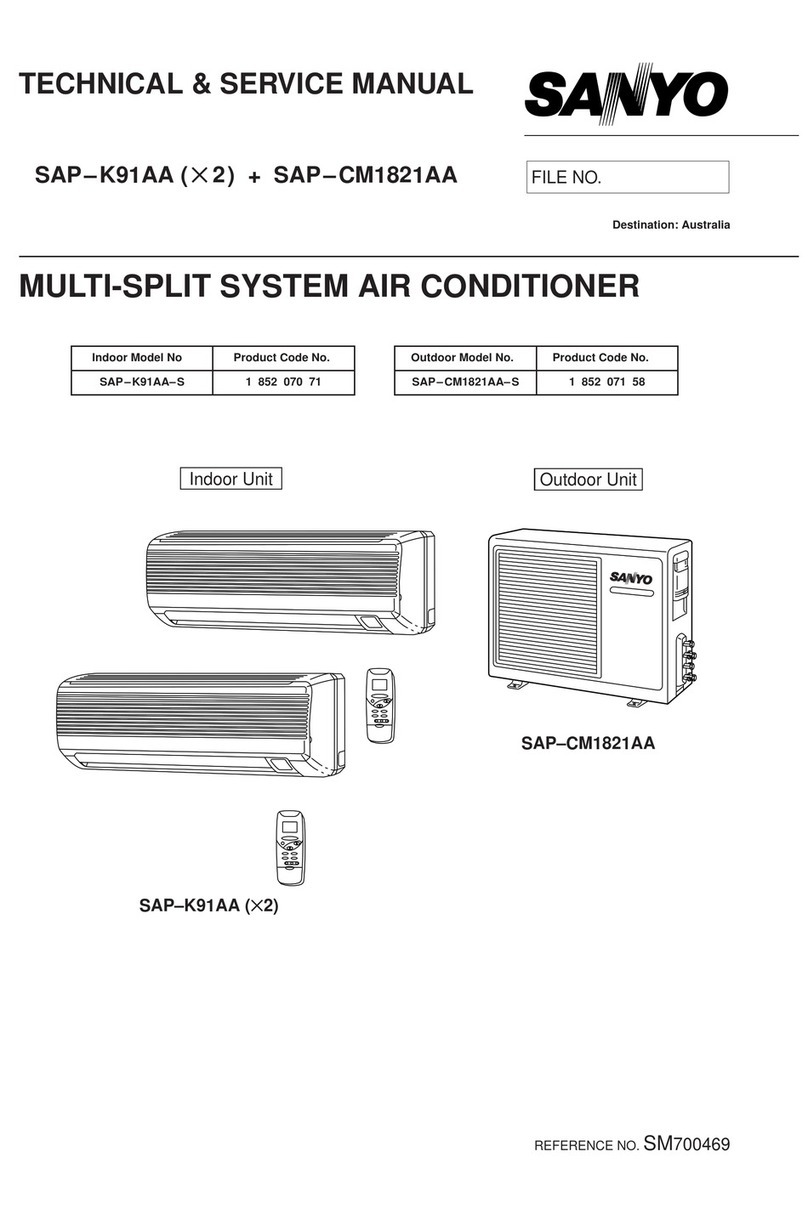
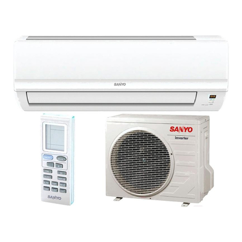
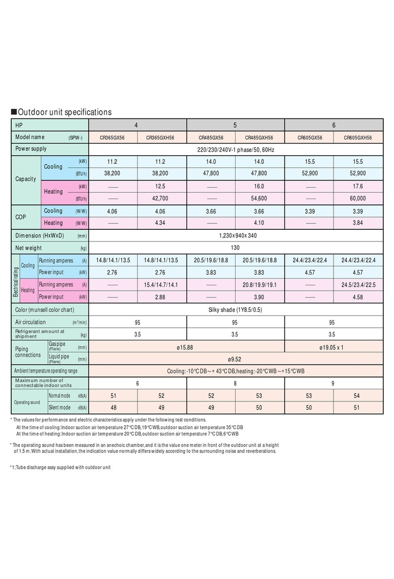
Sanyo KMS0912 User manual

SA&YO
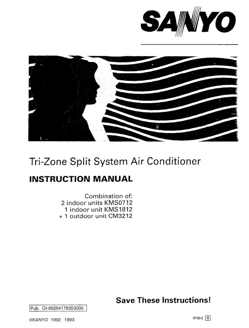
Dual-Zone Split System Air Conditioner
INSTRUCTION MANUAL
Combinationof:
2 indoor units KMS0912
+ 1 outdoor unit CM1812
Save These Instructions!
Pub. 01-85264179352000
OSANYO 1992, 1993 SY33-1

Contents
Product Information.
Alertsymbols.......„.....-
Installation Location
Electrical Requirements .
Safety Instructions ....... ......
Names of Parts
Using the Remote Control Unit.
Operation with the Remote Control Unit
1. Cooling.
2. Adjusting the Fan Speed .
3. Fan Only... ......... ..
Operationwithout the RornoteControl I-JOIt.......
Setting the
Adjusting the Airflow Direction................
Care and Cleaning .
Troubleshooting .
Tips forEnergy Saving
Operating Range ..........................
Product Information
2
2
3
.3
3
8
9
9
10
11
11
12
13
15
15
15
If you have problems or questions concerning your Air Conditioner, you
will need the following information. Model and serial numbers are on
the name plate on the right side of the cabinet.
Model No.
Date of purchase
Dealer'saddress
Serial No.
Phone number
Alert Symbols
The following symbols used in this manual,alert you potentially
dangerousconditions to users, service personnels or the appliance:
DANGER
WARNING:
CAUTION:
2
This symbol warns of immediatehazards
which will result in severe personal injury
or death. This symbol will be used in an
extreme case.
This symbol refers to a hazard or unsafe
practice which can result in severe personal
injury or death,
This symbol refers to a hazard or unsafe
practice which can result in personal injury
or product or property damage.
Olß5ZQ2

WARNING:
Avoid:
WARNING:
CAUTION:
01-352-03
Installation Location
We recommend that this air conditioner must be installed
property
by a qualified installation technician in accordance
with the Installation Instructions provided with the unit.
Before installation, check that the voltage of the electric supply in
your home or office is the same as the voltaqe shown on the
nameplate.
Do not install thié air conditioner where there are fumes,
flammable
gasses or extremelyhumidspace such as a green
house.ä
• Do not install this air conditionerwhereexcessively high
heat generating objects are placed.
To protectthe air conditioner from heavy corrosion, avoid installing
the outdoor unit where salty sea water can splash directly onto it or
in sulphurous air near a spa.
Electrical Requirements
1. All wiring must conform to the local electrical codes. Consult your
dealer or a qualified electricianfor details.
2. Each unit must be properly grounded with a ground (or earth) wire or
through supply wiring.
3. Wiring must be doneby a qualifiedelectrician.
e Power supply: 60Hz, single-phase, 230/208
volts.
Safety Instructions
Read this booklet carefully before using this air conditioner.
If you still have any difficulties or problems,consult your
dealer for help.
This air conditioner is designed to give you comfortable room
conditioners. Use this only for its intended purpose as
described in these Instruction
Manual.
Never use or store gasoline or other flammable vapors or
liquid nearthe air conditioner— it is very dangerous.
This air conditionerhas no ventilatorfor intaking fresh air
from outdoors. You must opendoors or windows frequently
when you use gas or oil heating appliances in the same room.
which consume a lot of oxigen from the air, Otherwisethere
is a risk of suffocationin an extreme
case.
Do not turn the air conditioner on and off from the power
mains switch. Use the operationON/OFF
button.
Do not stick anything into the air outlet of the air conditioner.
This is dangerous because the fan is rotating at high speed.
Do not let children play with the air conditioner.
Do not cool or heat the room too much if babies or invalids
are present.
3

Names of Parts
INDOOR UNIT
Air intake
Air outlet
Air intake Remote control
unit
Drain hose
Air outlet
Remote control
unit
NOTE:
Air intake
Air outlet
Remote Control Unit
Refrigerant Tubes
Drain Hose
Outdoor (Condensing) Unit
4
Drain hose
Refrigerant tubes
OUTDOOR UNIT
This illustrationis based on the external view of a standard model.
Consequently, the shape may differ from that of the air conditioner
which you have selected.
• This airconditionerconsists of 2 indoorunits and outdoorunit.2 indoor
units are combined with 1 outdoor unit. Each indoor unit can be operated
at the same time or independently.
Air from the room is drawn into this section and passes through air
filters which remove dust.
Cool air is blown out of the air conditioner through the air outlet.
The wireless remotecontrol unit controls power ON/OFF, operation
mode selection, temperature,fan speed, timer setting, and air sweeping.
The indoor and outdoor units are connected by copper tubes through
which refrigerant
gas flows.
Moisture in the room condenses and drains off through this hose.
The outdoor unit contains the compressor, fan motor, heat exchanger
coil, and other electrical components.
Oi-352aa

REMOTE CONTROL
receiver
OPERATION lamp
TIMER lamp
Operation selector
ON position
OFF position
WARNING:
CAUTION:
TEST position
01-352-05
Unit Display and Operation Selector
INDOOR UNIT
REMOTE CONTROL receiver
SANYO
TEST ON
opn TIMER
OPERATION lamp
TIMER lamp
Operation Flap
selector
This section picks up infraredsignals from the remotecontrol unit
(transmitter).
This lights when the system is in the continuous COOL or FAN mode.
This lamp lights when the system is being controlled by thetimer.
This position is for operatingthe air conditionerwith the wireless remote
control unit.Set the selector normally in this position.
Switch the selectorto the OFF position if you are not going to use the air
conditionerfor a few days or longer.
The OFF position does not disconnect the power. Use the main
power switch to turn off power completely,
This position is used only when servicing the air conditioner, so
don't leave the selector in this position.
5

Remote Control Unit
MODE selector switch
Timer selector switch
Fan speedselector switch
SENSOR
Transmitter
Display
ON/OFF operation button
Cover
Temperature setting
button
NOTE:
Timer setting buttons
PROGRAM button
NIGHT SETBACK button
6
Transmitter
00M
coot ER
FAN COOL TIMER
MODE
NORM. PROGRAM CLOCK
OFF ON PROGRAM
TIMER
LOW HIGH * NIGHT
SETBACK
MED. AUTO
FAN SPEED
SANYO
SENSOR
Display
ON/OFF operation button
Temperature setting buttons
Timer setting buttons
PROGRAM button
NIGHT SETBACK button
Cover
When you press the buttons or move the switches on the remote control
unit, the lamp at the tip of the unit flashes to transmit the setting
changes to the receiver in the air conditioner.
Information is displayed while the remote control unit is switched on.
The display shows the time and the room temperature at the remote
control unit when the unit is switched off.
This button is for turning the air conditioner on and off.
The cover opens from the left.Just pull it open.
Press "COOLER" button to change the set temperature down.
Press "WARMER" button to change the set temperature up.
You can press the temperaturesetting buttons keeping the cover closed.
First, press the PROGRAM button to select the mode you want.
Each time you press "HH" button,the hours advance by one.
Each time you press ''MM" button,the minutes advance by one.
For details, see "Setting the Timer".
Press this buttonto select the mode you want to program.
For details, see "Night Setback Mode". When you press this buttonin
the COOL mode, the mark appears at the lower left of the display,
and the remote control unit will automatically adjust the set temperature
to save energy.
01-352R)6

MODE selector switch
Timer selector switch
Fan speed selector switch
SENSOR
0186?07
Remote Control Unit (continued)
FAN:
COOL:
N0RM:
OFF:
ON:
PROGRAM:
AUTO:
HIGH:
MED:
LOW:
he air conditioner works only as a c.trculation
fan.
ho air conditioner makes the room cooler.
does not
i he atr conditioner at the time.
he (.oruflttonor starts at the time.
The air Atop:;and starts, or starts and stops, at
t
ho set
air the fan
High speed for faqtcooling
Medium speed
Low speed
A temperature sensor inside the remotecontrol unit senses the room
temperature.

Using the Remote Control Unit
How
to Install Batteries
Slide to open 1. Press and slide tho the back of the remotecontrol ornit
in the
direction of tho arrow.
2. Install two AAA alkaline?
batterios. Make r,wre
the batter'es point in the
direction marked in the battery
3. Press the ACI- button, then replace the tic'. if vou preo.3
it, the current
time, ON time, and OFF time are aJl reset to,0 00. Thi3 may make it
easier for you to resetthose (See the Timer".)
ACL button The batterieslast aboutsix months,dependingon how much
NOTE* you use the remotecontrol unit- Replace the batteries when
the remotecontrol unit's lamp fails to light, or vvhenthe
remotecontrol cannot be used to change the air conditioner's
settings.
Use two fresh leak-prooftype-AAA alkaline batteries.
In replacing batteries,follow the instructions as mentioned
in thesub-section "How to Install Batteries".
If you do not use the remotecontrol unit morethan 1 month,
take out the batteries.
How to use the Remote When using the remotecontrol unit, always point the unit's transmitter
Control Unit head directly at the air conditioner's receiver.
Air conditioner
Remote Control Unit Receiver
(Transmitter head)
Remote Control Unit The indoorremoteunit may be operated
eitherfrom a non-fixed positionor
Instllation Position from a wall-mounted
position.To ensure thattheair conditioneroperates
correctly, do not install the remotecontrol unit in the following places:
Rear
plate
Remote
control unit
mounting
cradle
Remote
control
unit e
•
e
In direct sunlight
Behind a curtain or other places where it is covered
Morethan 26 ft. away from the air conditioner
In the path of the air conditioner's airstream
Where it may become extremely hot or cold
Where it may be subject to electrical or magnetic noise
1. If Non-fixed Position
Raise the rear plate of the remotecontrol unit mounting cradle and insert
the remotecontrol unit.The unit can be used either in that position
(placed on a table, for instance) or held in the hand.
2. If Wall-mounted
Fixed Position
Install the remote
control unit at a convenient location on a nearby wall.
However, before attaching the remote control unit mounting cradle,
check that the remotecontrol unit can operate frojn the desired wall
position.

Operation with the Remote
Control Unit
TEM@
C)N4/OfFO STEP 3
COOLER STEP 4
FAN COOL TIMER
NORM PROGRAM CLOCK
OFF 0M CZZZD
agijij— PROGRAM
TIMER
LOW HIGH NIGHTSETBACK
MED AUTO
STEP 5 FAN SPEED
NOTE:
1. Cooling
NOTE:
CAUTION:
01-352-09
Check that the circuit breaker on the power panel is turned on and the
operation selector of the indoor unit is in the ON position.
STEP 1:
STEP 2:
STEP 3:
STEP 4:
STEP5:
Set the MODE selector switch to COOL
Set the timer selector switch to NORM.
Press the ON/OFF operationbutton.
Press the COOLER or WARMER buttonto set a cooler or
warmer temperature.
Each time you press these buttons,the set temperature
varies by 20 F.
840F max.
640 F min.
Set the fan speed selector switch to the setting you want.
To stop the air conditioner, press the ON/OFF operaion button again.
Choose the best position in the room for the remote control
unit, which also acts as the sensor for room comfort and
transmits the operating instructions. Once you've found this
best position, always keep the remote control unit there.
This appliance has a built-in 3-minutetime delay circuit to ensure
reliable operation. Ifthe operationbuttonis pressed, the compressor
will start running afterthree minutes. In the event of power failure,
the unit will stop. When the power is applied, the unit will re-start
automatically after3 minutes.
To preventthe appliance from malfunctioning, do not set any
selector switch between
two indicated positions. Makesure
that it clicks into position.
9

Night Setback Mode
in Cooling
What does the Night
Setback mode mean?
2. Adjusting the
Fan Speed
A. Automatic
10
Operation with the Remote Control Unit (continued)
CD
CO
FANcorn- TIMEP
NORM. PROGRAM CI_OCK
ON CSC-D
TIMER STEP 1
LOW HIGH
MED. AUTO
FAN SPEED
STEP 1: Press the NIGHT SETBACK buttonin cooling.
The mark appears atthe lower left of the display.
Press the NIGHT SETBACK buttonagain to release the night setback
function. This button has no effect in the FAN mode.
Room
Setting Temperature
Temperature
20F
30 minutes 30 minutes Time
Inthis mode.the air conditioner will cool the room to the set
temperature,and then the thermostatwill make the unit pause. After
about 30 minutes, the air conditioner will automatically raise the set
temperatureby 20F. When the room temperature reaches the newly set
value, the thermostatwill cause the unit to pause. After about 30 minutes
the temperaturewill again be raised by 20F. This enables you to save
energy without
sacrificing comfort.
This function is convenient when gentle cooling is needed.
STEP 1: Simply set the FAN SPEED selectorto the "AUTO" position.
A microcomputer in the air conditioner automatically controls the fan
speed when the AUTO mode is selected. When the air conditioner starts
operating, the difference between the room temperature and the set
temperatureis detected by the microcomputer which then automatically
switches the fan speed to the most suitable level.
Olß52ao

B. Manual
3. Fan Only
INDOOR UNIT
SANYO
OFF
Operation selector Flap
01-352-11
Operation Withthe Remote Control Unit (continued)
Cooling mode:
Whendifference between FAN SPEED
room temperature and set
temperature is
F and over
Between 4T and 2' fM
Odium
Below 2G F Low
If you want to adjust fan speed manually during cooling, just set the FAN
SPEED selector desired. [HIGH. MED., or LOW]
ROOM SET
TEMP. TEMP.
ON-I/OFF•O STEP 2
COOLER WARMER
FAN COOL TIMER
STEP 1 MODE
If you want to circulate air without any temperature control, follow these
steps:
STEP 1: Set the MODE selector switch to FAN.
STEP 2: Press the ON/OFF operation button.
Operation without the Remote
Controi Unit
If you have lost the remotecontrol unit or it has trouble, follow the steps
below.
1. When the air conditioner is stopped.
If you want to turn on the air conditioner, switch the operation selector
to the OFF position, and then to the ON position.
The set temp. and fan speed are automatically set
NOTE; at the latest selection before stopping.
2. When the air conditioner is running.
If you want to turn off the air conditioner, switch the operation selector
to the OFF position.

1 ) How to set the
present time
2) How to set the
OFF time
( • _7t_t
ROOM SET
TEMP. TEMP.
3) How to set the ON
time
71_1
ROOM SET
TEMp. TEMP.
4) How to set for daily
ON/OFF operation
PM
ROOM SET
TEMP. TEMP.
12
Setting the Timer
(Example) To set to 9:10 p.m.
Operation
1. Press the PROGRAM buttonthree times.
The time indication alone flashes.
2. Press the HH buttonuntil 9 and are
displayed.
Press the MM button until 10 is displayed.
The dispiay will automatically stop flashing
except for the symbol after 10 sec.
(Example) To stop the air conditioner at 11:30
p.m.
Operation
1. Press the PROGRAM button once. The
timer OFF and time indications flash.
2. Press the HH buttonuntil 11is displayed.
Press the MMbuttonuntil 30 is displayed.
The display will change automatically back
to show the present time after 10 sec.
3. Set thetimer switch(es) to OFF.
4. Press the ON/OFF buttonto start the air
conditioner.
(Example) To startoperationat 7:10.
Operation
1. Press the PROGRAM buttontwice. The
timer ON and time indications flash.
2. Press the HH button until 7 and (ÄO are
displayed.
Press the MMbuttonuntil 10is displayed.
The display will change automaticallyback
to show the present time after 10sec.
3. Set the timer switch(es) to ON.
4. Press the ON/OFF buttonto startthe air
conditioner.
Indication
flashing
flashing
Indication
flashing
flashing
Indication
flashing
flashing
(Example) To startoperation
at 7:10and stop the air conditionerat
11:30 p.m.
1. Set the timer ON/OFFtimes as shown in 2)
and 3).
2. Set the timer switch(es) to PROGRAM.
3. Press the ON/OFF button to start the air
conditioner.
01-352-12

NOTE:
Indoor Unit
Zone "A" 300
for
COOLING
01-352-13
Power failure during timer operation
If power failure occurs, thetime counted upto that pointwill become
void. After the power is applied, the timer newly starts counting at the
set time.
Adjusting the Airflow Direction
A. Horizontal
The horizontalairflow can be adjusted by moving the vertical vane to the
left or right.
B. Vertical
Hold both ends of the flap and move the flap up and down to adjust the
vertical airflow. In the COOL mode, don't direct the flap down more than
300; otherwise, condensation may drip on to the floor. Zone "A" is the
recommended flap position for cooling.
Left Right
Vertical vane
Up
Flap Down
13

Care and Cleaning
WARNING:
Casing and Grille
(IndoorUnit)
CAUTION:
Air filter
How to removethe filter
14
1. For safety, be sure to turn the air conditioner off and also to
disconnect the power before cleaning.
2. Do not pourwater on the indoor unit to clean it. This will
damage the internal components and cause an electric shock
-3
hazard.
Clean the casing and grille of the tncjoor
unit with a vacuum cleaner
brush, or wipe them Witha clean, soft cloth.
If these parts are stained, use a clean cloth moistened vvith
a rnild liquid
detergent. When cleaninq the grille, be careful not to force the vanes out
of place.
1. Never use solvents, or harsh chemicals when cleaning the indoor
unit. Do not wipe the plastic casing using very hot water.
2. Some metal edges andthe fins are sharp and may cause injury if
handled improperly: be especially careful when you clean these
parts.
3. The internal coil and other components of the outdoor unit must be
cleanedevery year. Consult your dealer or service centre
Air Filter
Pull down
FRONT
The airfilter behindthe air intakegrille should be checked and cleaned at
least once every two weeks.
1 . Movethe flap on the air outletgrille to its lowest position.
2. Hold the air filter by the tab at the bottom, and pull downward.
Use a vacuum cleaner to remove light dust. Ifthere is sticky dust on the
filter,wash the filter in lukewarm,soapy water, rinse it in clean water,
and dry it. When replacing the filter, make sure that the FRONT mark is
facing you
01-352-14

Troubleshooting
Ifyour air conditioner does not work properly, first check the foilowinq points beforerequesting service. If it
still does not work properly, contact your dealer or service centre.
Trouble
Air conditioner does not
run at all
Compressor runs but
soon stops
Poorcooling peformance
Do not:
Do
01-352-15
Possibto Cause
Power failore
2. Leakaoe breaker tripped
3. Linevoltaoe too low
1
2.
3.
Remedy
Restore power
Contact service centre
Consult with electrician or dealer
4
5.
1.
1
2.
3.
4.
5.
Operationbutton is Off
Batteries tn remote control unit
have run down
Obstruction in frontof condenser
coil
Dirty or clogged air filter
Heat source (cooker, heater, or
electrical appliance) or many
people in room
Doors and/orwindows are open
Obstacle near air intakeor air
discharge port
Thermostat is set too high
5.
1.
1.
2.
3.
4.
5.
Press the buttonagain
obstruction
Clean air filter to improve airflow
Eliminate heat source if possible
Shut them to keepthe heat out
Remove it to ensure good airflow
Set the temperaturelower
Tips for Energy Saving
Block the air intake and outlet of the unit. If it is obstructed,
the unit will not work well, and may be damaged.
Let direct sunlight into the room. Use sunshades, blind or curtains.
If the walls and ceiling of the room are warmed by the sun, itwill
take longer to cool the room.
Always try to keepthe air filter clean. (Referto "Care and Cleaning").
A clogged filterwill impair the performanceof the unit.
To preventconditioned air from escaping, keepwindows, doors and
any other openings closed.
Operating Range
Temperature
Maximum
Cooling
Minimum
Indoorair intake Outdoorairintake
950F DB/- 1150F DB
750FWB
670F DB/- 670F DB
570F
15

in canacia
SANYO Canada inc.
Toronto,
Ont
MAH IMO
SANYO FISHER(USA)Corp.
2 1350 Lassen Street
Chatswocth. Caiit. 1
This manual suits for next models
1
Table of contents
Other Sanyo Air Conditioner manuals

Sanyo
Sanyo 26KS72R User manual

Sanyo
Sanyo KS0911 User manual

Sanyo
Sanyo COOL User manual

Sanyo
Sanyo STB0810C1 Operating manual

Sanyo
Sanyo STB0810C1 User manual

Sanyo
Sanyo XS1822 / CL1822 User manual

Sanyo
Sanyo KMS0712 User manual

Sanyo
Sanyo KHS1232 User manual

Sanyo
Sanyo KMS1812 User manual
Sanyo
Sanyo KS2432A User manual

Sanyo
Sanyo 36KS82 Installation and user guide

Sanyo
Sanyo C4272R S/C User manual

Sanyo
Sanyo SAP-FDRV96EH User manual

Sanyo
Sanyo KS1872 User manual

Sanyo
Sanyo RS3622 User manual

Sanyo
Sanyo SAP91KC User manual

Sanyo
Sanyo CMH1972A Operating manual

Sanyo
Sanyo SPW-FTR124EH56 User manual

Sanyo
Sanyo 2TS32A User manual

Sanyo
Sanyo C4272R User manual