manuals.online logo
Brands
  1. Home
  2. •
  3. Brands
  4. •
  5. Sanyo
  6. •
  7. Microwave Oven
  8. •
  9. Sanyo EM-S889 User manual

Sanyo EM-S889 User manual

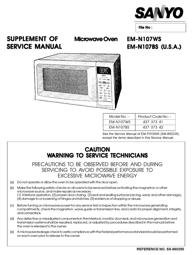
SUPPLEMENTOF
SERVICE MANUAL Microwave Oven
IFILE NO. I
EM-S889 (New Zealand)
m’
n
,AL[[) ,SM.\OR
eo
3F!?HFILLET 4POTATO
—START —
5vEGEWIES 6Cd55ERCLE
Product Code No. 43731423
See the service manual of EM-S829(SM-860043) except
the items described in this service manual.
Foreword
Read this manual carefully, especially precaution on microwave energy, and follow the procedure strictly.
Careless servicing and testing may expose yourself to the microwave energy leakage.
PRECAUTIONS
PRECAUTIONS TO BE OBSERVED BEFORE AND DURING SERVICING TO AVOID POSSIBLE EXPOSURE TO
EXCESSIVE MICROWAVE ENERGY
(a) Do not operate or allow the oven to be operated with the door open.
(b) Make the following safety checks on all ovens to be serviced before activating the magnetron or other microwave
source, and make repairs as necessary:
(1) Interlock operation, (2) proper door closing, (3) seal and sealing surfaces (arcing, wear, and other damage),
(4) damage to or loosening of hinges and latches, (5) evidence of dropping or abuse.
(c) Before turning on microwave power for any service test or inspection within the microwave generating compartments,
check the magnetron, wave guide or transmission line, and cavity for proper alignment, integrity, and connections.
(d) Any defective or misadjusted components in the interlock, monitor, door seal, and microwave generation and transmis-
sion systems shall be repaired, replaced, or adjusted by procedures described in this manual before the oven is
released to the owner.
REFERENCE NO. SS-860045
—TABLE OF CONTENTS —
Specifications . . . . . . . . . . . . . . . . . . . . . . . . . . . . . . . . . . ...1 Test Procedures . . . . . . . . . . . . . . 3
Power Output Measurement . . . . . . . . . . . . . . . . . . . . . . . . . 1Exploded View and Parfs List . . . . . . . . . . . . . . . . . . . . ...4 -8
Circuit Diagram ....................................2 Overall Circuit Diagram ...........................9-1o
1. SPECIFICATIONS
Rated Power Consumption
Microwave Output
Frequency
Power Supply
Rated Current
Safety Devices
Timer . ...........
Overall Dimensions ..............
Oven Cavity Size ..................
Turn Table Diameter ..............
Effective Capacity of
Oven Cavity . .
Net Weight . . .
1330W
91OW
(Adjustable 130Wthrough 910W)
2,450MHz~50MHz
230V-240V,50HZ
6.0 Amp.
Thermal Protector, Open at 122°C
for Cavity
Thermal Protector, Open at 122-C
for Magnetron
Fuse (Cartridge Type 8A)
Primary Interlock Switch
Door Sensing Switch and Relay2
Interlock Monitor Switch
Electronic Digital, up to
99 min. 99 sec.
550(W) x451(D) x311(H) mm
375(W) X404(D) x236(H)mm
360mm
32 liters
Approx. 20 kg.
2. POWER OUTPUT MEASUREMENT
NOTE
(c)
(D)
(E)
(F)
(G)
1.
2.
1,
2.
1.
2.
3.
Set cooking time to two (2) minutes. (“2 00’’ appears in
display)
Touch START key and operate oven for exactly two (2)
minutes.
Take out the two bowls at once,
Stir both water with thermometer and measure the water
temperature rise respectively.
Get temperature rise by calculating the difference (water
temperature after cooking minus initial temperature) in
each bowl.
Then calculate average value(t) of both temperature rises
in degrees centigrade.
Then workout;
Power Output (watt) =70 xAt
Power output shall be in the following range
Average Microwave
temperature rise Power output
Minimum
10.4”C 728W
Maximum
13.3°C 931W
Power Output will be influenced by line voltage of power
supply. Consequently, correct power output must be
measured within 240 VAC~2volts while unit is operating.
The power output specification, 910Won this model is measured
with IEC measurement. The power output is measured with two (2)
liters water isequivalent to910Win measurement with IEC, when
measured with the following power output.
(A) 1, Fill twotest bowls with eachl Iiter water respectively.
2. Use accurate temperature “C and measure each water
temperature respectively.
(B) Place thetwobowls on glass turntable.
–l–
3. CIRCUIT DIAGRAM
230-240V*50HZ
+
:\21
BL =BR
~._———
IN ‘L; Ll, L2 -650LIH
,cl -o.066y F
l~m r8.OA(T) ,C2, C3 2200PF CAVITY
11..11 THERMAL PROTECTOR
IOPENS AT 122+5°C
,C2
wI
MAGNETRON L_____ ___J
THERMAL PROTECTOR
OPEN SAT 122+5°C w
w
INTERLOCK MONITOR
wINTERLOCK SWITCH “NO
BK
–1
—I
II r’ NC
I
COM Y
wBLOWER MOTOR
l--y--l
Y
wY
w
II II
~1 1~ IGEAR MOTOR
II 1/ w
——— -——“I&J‘
—CONNECTOR
— — — —— S201
1HUMIDITY
SENSOR
RELAY2 zq’- IBK ~------
9
@l ‘j :‘R kj!% >:
fl
—3~w ,
1.—_— ——_
1000R
+HIGH VOLTAGE TRANSFORMER
I–––––––––––-
CONNECTOR
S1
—ITl
Iu
I3
I“
I6
“
I
I
I
.—
,
I1
-1 1~ ~ ~
IEl I
L ______ _. ______( )J
77i- FUSE DIODE
FFA
R
mm
o
~DIODE
h
RELAY 1
STEP DOWN
TRANSFORMER
10–1
c
E●I
●1X1, I
BL
CONNECTOR I
S102 I
CIRCUIT I
BOARD
CONNECTOR
.I!tm
TOUCH
Slol KEY
BOARD
———––l
[–––l 7)7 7)7 ,.,”,
CAPACITOR
MAGNETRON 2.1 KV
RESISTOR
— — — 1OMEG-OHM
WIRINGCOLOUR
BR:BROWN
BK: BLACK
0:ORANGE
BL :BLUE
W:WHITE
Y:YELLOW
R:RED
ISECONDARY
INTERLOCK I
IPRIMARY INTERLOCK DOOR
SWITCH MADE. INTERLOCK MONITOR SENSING IRELAY 2I
SWITCH SWITCH SWITCH
CONDITION COM CoI/l COM COM
NO NC NO NO Parts marked with this sign aresupplied with
high voltage exceeding 250V.
Parts marked with this sign have special
characteristics important for microwave leakage
When replacing any of these parts use only
manufacturers specified parts.
DOOR OPEN ●
DOOR CLOSE ●●●
..
–2–
4. TEST PROCEDURES
COMPONENT
TOUCH KEY
BOARD
r——— ——— .
CHECKOUT PROCEDURE
Measure the resistance between terminals of
FPC connector after removing it from S101.
(Figure 1).
NOTE
-When reconnecting the FPC connector, make
sure the holes on the connector are properly
inserted in hooks of the plastic fastener in S101.
MATRIX CIRCUIT FOR
TOUCH KEY BOARD
FPC CONNECTOR
——— ——— ——— —.— ——— — 7
Measure the voltage: Between test points TP-1,
TP-2, TP-3, TP-4 or TP-5 and ground between TP-
6 and TP-7. (See control circuit board on page 8.)
CONTROL
CIRCUIT BOARD
NOTE
–Proceed with the check of the step-down trans-
former, to see if any one of the measured value is
different from the specified values.
RESULT
Resistance
value
=-E=’
When checking “START” key, connect ohm-
meter as illustration below.
ohm-meter
:)’%
-----
-----I
---- -
~
--- -- I
---- - I
--- .
---- - I
----
---- -
~
--- - I
--- -
---
\
Al
)
A2
A3
A4
A5
c1
C2
c3/
C4
C5
TERMINALS OF FPC CONNECTOR Figure 1
==El=
Test TP-5 TP-61
Point TP-7
=Fl
tl
-15V –25V
DC DC
–3–
5. EXPLODED VIEW AND PART LIST
CAVITY PARTS
*** ALL SERVICE ON MICROWAVE OVENS SHOULD BE PERFORMED BY A QUALIFIED TECHNICIAN USING
-- APPROVED TESTING EQUIPMENT. CUSTOMERS SHOULD NOT ATTEMPT TO REPLACE PARTS
IDENTIFIED BY A TRIPLE ASTERISK (***)
:ey
io.
1
2
3
4
5
6
7
8
9
10
11
Part No.
6171246377
4110825201
411 1606007
6171385113
411 1606106
6171683295
6171512458
4110105808
6171451399
6171445435
4110110802
“Item not illustrated
Description
Cabinet (Also order circuit diagram
when replacing Cabinet)
Screw, Truss Hd. Tapping, 4x1 Omm
Screw, TPG TRS +SRT 4x1 Omm
Power Cord
Screw, S-TPG TRS +SRT 4x10mm
Oven Cavity ‘“ (Not service Part)
Gear Motor
Screw, Pan Hd. Machine, 4x1 Omm, Brass
N1
Bottom Plate ‘“ (Not service Part)
Plastic Foot with Canoe Clip
Bolt, Hex Hd. Machine with Spring Washe
&Bolt Washer, 5x14mm, 21 ‘“
Q’ty
1
11
2
1
1
1
1
2
1
4
2
:ey
40.
12
13
14
15
16
17
18
19
20
21
22
23
24
25
26
,
●
Parl No.
6171240795
4110892500
6171208481
6171444476
6171242416
6171098372
6171621952
6171621938
4110691707
4110076900
6171241235
6170805315
6171281149
6171473865
6171756203
6171821956
6171799538
Description
Hinge, Lower ““”
Washer F5x1 OXO.8
Insulation Sheet
Turntable Shaft
Roller
Rotating Tray
Antenna
Cavity Cover
Screw, TPG TRS 4x6mm, Stainless
Screw, PAN. HD. Tapping, 3x6mm, Z1
Thermostat, Cavity 122°C
Special Washer
Duct Humidity Sensor
Humidity Sensor
Special Washer
Name Plate
Circuit Diagram
Q’ty
1
1
1
1
1
1
1
1
1
2
1
1
1
1
1
1
1
-4-
SWITCHES AND MICROWAVE PARTS
~Y~ ‘\B
@Parts marked with this sign have special
characteristics Important for microwave leakage
When replaclng any of these parts use only
manufacturers specified parts.
*** ALL SERVICE ON MICROWAVE OVENS SHOULD BE PERFORMED BY A QUALIFIED TECHNICIAN USING
APPROVED TESTING EQUIPMENT. CUSTOMERS SHOULD NOT ATTEMPT TO REPLACE PARTS
IDENTIFIED BY A TRIPLE ASTERISK (***)
[ey Part No. Description Q’ty
~o.
1 4110825201 Screw, Truss Hd, Tapping, 4x1 Omm 6
2 6171685657 H.V.Transformer, N5T-S829ML 1
3 6171621945 Stay, Cavity &Magnetron 1
44110076900 Screw, Pan Hd. Tapping, 3x6mm, C2 1
5 6171241235 Thermostat, Magnetron, 122-C 1
6 4150019301 Magnetron, 2M218H (N) ‘“ 1
7 4230227503 Fuse, 250V 8A 1
8
9 6171451627 Lead Wire Ass’y (including Diode) 1
10 6171621990 Space Parlitlon (Blower) 1
11 6171449716 High Voltage Capacitor including Resistor, 1
l.luf 2.1 KV
12 6171622041 Capacitor Band 1
13 4110115609 Bolt Hex 4x1O 21 4
14 6171621983 Duct, Msg. Exhaust 1
15 6171103618 Lamp, 240V 25W 1
16 6171241280 Lamp Socket 1
17 6171305685 Blower Motor 1
(ey
Vo.
18
19
20
21
22
23
24
25
26
27
28
29
30
31
32
33
Parl No.
4110772109
6170751179
6171241181
6171670523
6170045575
6171670523
6171241174
411 1025907
6171173505
6171405354
6171778311
411 1606106
6171325713
Description
Screw, Tapping, Bin 4x20mm
Blower Fan
Latch Lever ‘“
Micro Switch, Primary Interlock V-5P030FB ‘“’
Micro Switch, Interlock Monitor
V-5220DZ ‘“
Micro Switch, Door Sensing V-5P030FB”*
Lever Stopper ‘“’
SCR E-TPG TRS +TW 4x10mm
Harness, Door Sensing
Lead Wire Ass’y
P,C.B, Comp
SCR.S.TPG +TRS 4X10
Insulation Sheet
Q’ty
—
2
1
1
1
1
1
1
2
1
1
1
1
1
–5–
DOOR PARTS
--
4***
1(-J***
9***
*** ALL SERVICE ON MICROWAVE OVENS SHOULD BE PERFORMED BY A QUALIFIED TECHNICIAN USING
APPROVED TESTING EQUIPMENT. CUSTOMERS SHOULD NOT ATTEMPT TO REPLACE PARTS
IDENTIFIED BY A TRIPLE ASTERISK (***)
(ey Part No. Description Q’ty
tie.
16171520934 Door Cover ‘“ 1
2 6171520941 Door Panel ““ 1
3 6171365908 Door Main Frame (White) ‘-” (Also order 1
Door Sheet when replacing Door Main
Frame)
46171520958 Choke Dielectric ‘“ 1
5 6171246483 Door Sheet 1
6 4110541903 Nut, Hex. Hd. with Washer, 5mm ●*’ 2
<ey
No.
7
8
9
10
Part No.
6171240955
4110110802
617101 1494
617101 1487
Description
Hinge, Upper ‘“
Bolt, Hex. Hd, Machine with Spring
Washer and Bolt Washer, 5x14mm,
ZI “+
Spring ““
Door Latch ‘“
Q’ty
1
2
1
1
.
–6–
CONTROL PANEL PARTS
2***
1
1 ***
\
36\
8***
11 ***
*** ALL SERVICE ON MICROWAVE OVENS SHOULD BE PERFORMED BY A QUALIFIED TECHNICIAN USING
APPROVED TESTING EQUIPMENT. CUSTOMERS SHOULD NOT ATTEMPT TO REPLACE PARTS
IDENTIFIED BY A TRIPLE ASTERISK (***)
(ey
’40.
1
2
3
4
5
6
Parl No.
6171762075
6171623512
6171514346
6171521030
411 1606205
Description
Control Sheet ‘“ (Also order Touch Key
Board when replacing Control Sheet)
Touch Key Board ‘“ (Also order Control
Sheet when replacing Touch Key Board)
Control Plate
Control Frame ““
Screw, Tapping, TRS +SRT 4x10mm
PRINTED MATTER (Items Not Illustrated)
Q’ty
1
1
1
1
1
+
Key Part No.
No.
6171762099
6171461077
6171621970
Description Q’ty
III
(ey Parl No. Description Q’ty
Vo.
7 6171623161 Control Base Ass’y ‘“ 1
6 6171756672 Control Clrcult Board Complete ‘“ 1
9 411 1295605 Screw, Bind Hd. Tapping, 3x1 Omm, Z1 2
10 6170809559 Spring, Door Release Lever 1
11 6171514339 Door Release Lever ‘“’ 1
–7-
CONTROL CIRCUIT BOARD
(Part No. 617175 8672)
(14500) C-O AH CS-40 94v-()@* \
oI—.—————
———————————
,,,1~:: [===1 +%
J101
‘; e
.=
R127\ UI
m‘
’26m o
~fia ;z
,23m D!
Q.—\ --81
.
>
0
I05
113
Cj
o
>IJ
)
*—
0
m
1-
0
—
\/
\---
o
TP-6
TP-7
TP-4
TP-I
GROUND
TP-2
TP-5
TP-3
–8–
6. OVERALL CIRCUIT DIAGRAM
L
R143
10K
11 P611ANI
P601AN0
P50
P71
P70
CN
P45 ~
N
w
z
P477r3 J
‘46/T
355
J54 -
J53 -
352 0
~51 —
‘67(AN7
’27
’26
’25
’24
=
~41/lNTl
‘40/1 NTO
(RFF
(Cc
IL
R142
------ ------
II10K
SI02 I1:
----- ----- ----- ---
I
Ik,oKm :
DIOI 1SS132
IRIOIU /50Vk’
m18
II
IDOOR JL
SENSING D102 –5V I
ISWITCH 1N4002 470<> 470<2 I
I~QQ~ --‘l~K- ‘1Q1OI I
ISENSING
[CIRCUIT I
II
~-----
OPENd
I
II
II
IRI04
270 I
AC230 240V
50Hz
*P
SWITCH
BLOWER
MOTOR
GEAR
MOTOR
r-t-a
y~
:
RL2
INTERLOCK
MONITOR
SWITCH
I
I
1
I
I
I
I
I
I
I
I
I
I
I
C!I03 DTA143X I
RL2
Q102
C3330 I
DI04 I
1SS132 I
1
RLI RI06
3300 1
I
,MAIN
,CONTROL
,CIRCUIT
L-----.–----L- ------- L------ -2
I
I
I
IBUZZER
iDRIVE
is’fls!’l ---
R116 47K
Q104 DTA143X 1
‘--l~K-’ 1
RIIO I
33K I
,1”
BZI L--—- .
R109 I
-15V IK I
---- -——- ---- ---- ---- _,.
M
‘B
●~11
II
,4+- , 1-
I
I
I_ __’
MAGNETRON
.
—
1-
1
I
I
I
I
I
I
I
I
I
I
I
I
I
I
I
I
I
I
---- --—
KEY
BOARD
CIRCUIT
I(1) (2) (3) (4)
016 II1I
1
t
,---
1
I
I
I
I
1
I
I
I
I
I
I
I
I
I
I
I
I
I
I
I
I____
•+
K
1S1
—
28POTATO HI/LQ ;;:::; @R1254,, lK 34
3R126.,, lK 35
9CASSEROLESTART VEGETABLES~
1RL1
:1
1[
-.
---- ---- ---- _J-------------- _-
, , , 1
t4FISH
FILET .
---- --- --- --- --- --- __ I
-+------’ )11 D13 1C106 o+0 7V
IN4002 1N4002 ZDII
23:?
uRD56ESB3
-.. LIct3~
,RD13ESB2
C1l zI-C14
1Ooop -O.lp
:
/25V G/25V
a
E[
‘PT--–-FI1
nfi
I* “1
I
I
I
Ia
n!,
4,7K .47p
Ilov
-5V
Q11 A564A
—–,,,, b-5V ----- ----- -- i
IiJl1;-+$<
“,..
cl x–15V
ZD12
gl C12 +: RD27ESBI
47P
150V ~R12 Q12
r56K A564A -25V
D12 ZD13
s3j 1N4002 RD39ESB2
“1 R131,,220Q VF
R15 IOK
R14’’”22OQ
PI S4 VF
-------- POWER
PT1 P05M V690 SUPPLY
---- ---- ---- ---- ---- ---- ---- .CIRCUIT”---- -
INITIALIZATION ID106
CIRCUIT
:%
CIRCUIT
I
I
I
I
---- ---- ---- ---- ---- --
–9–
P30
P31
P32
P33
P34
P35
P62/AN2
(PD)P17
(PD)P16
(PD)P15
(PD)P14
(PD)P13
(PD)P12
(PD)Pll
(PD)P1O
(PD)P07
(PD)P06
(PD)P05
(PD)P04
(PD)P03
(PD)P02
(PD)POI
(PD)POO
VEE
P37
P36
P66/AN6
P65/AN5
P64/AN4
P63/AN3
P44
P43
P42
P20
P21
P22
P23
XIN
XOUT
Vss
AVSS
---- ---- ---- ---- -— -- ---- ---- —--- ---- ---- ---- --
II
II
RB251 1
‘t
I–12V
$4 I
!5 ‘6 3G
I‘5 2G ~
4. I14
I
!8 i11 ‘
19 I10 ::
jO I
jl 9Da
I
j2 8E
I
j3 7F
1
j4 6G
,
j5 5H
~I
UOPEN
I________ –______ ---------------
a
j7 R128 10K
;8 R129 10K
R137 IOK
rR136 IOK
IR130 t
IR131 oI
II
!2 R132
!3 R133 o. ,
●
Sf 0)
RS1
-----
~pxz ;
11 T,2
-----
H–5V
l-----------
p-g:
~OPEN
=VF
I
I
I
I
I
I
I
I
I
I
I
I
I
%) I
I
I
DISPLAY :
TUBE I
CIRCUIT :
---— --—- —-—- —--— -
–lo–
.—
Wf!’’’o’o
December ‘95/1 00 LT Printed in Singapore SANYO Electric Co., Ltd.
Osaka, Japan.

Other manuals for EM-S889

1

Other Sanyo Microwave Oven manuals

Sanyo EM-C950 User manual

Sanyo

Sanyo EM-C950 User manual

Sanyo EMS9515W - 1.4 Cubic Foot Capacity Countertop Microwave... User manual

Sanyo

Sanyo EMS9515W - 1.4 Cubic Foot Capacity Countertop Microwave... User manual

Sanyo EM-S2585V Use and care manual

Sanyo

Sanyo EM-S2585V Use and care manual

Sanyo EM-M470WS User manual

Sanyo

Sanyo EM-M470WS User manual

Sanyo EMS6588S - USA Countertop Microwave Oven 1.0 cu.ft. Capacity... User manual

Sanyo

Sanyo EMS6588S - USA Countertop Microwave Oven 1.0 cu.ft. Capacity... User manual

Sanyo EMX-412 User manual

Sanyo

Sanyo EMX-412 User manual

Sanyo EMC 1900M User manual

Sanyo

Sanyo EMC 1900M User manual

Sanyo EM590 User manual

Sanyo

Sanyo EM590 User manual

Sanyo EMN-109 User manual

Sanyo

Sanyo EMN-109 User manual

Sanyo EM-S8588V User manual

Sanyo

Sanyo EM-S8588V User manual

Sanyo EMS6588S - USA Countertop Microwave Oven 1.0 cu.ft. Capacity... Use and care manual

Sanyo

Sanyo EMS6588S - USA Countertop Microwave Oven 1.0 cu.ft. Capacity... Use and care manual

Sanyo EMS 1001 User manual

Sanyo

Sanyo EMS 1001 User manual

Sanyo EM-S7720B User manual

Sanyo

Sanyo EM-S7720B User manual

Sanyo EM-S2585W User manual

Sanyo

Sanyo EM-S2585W User manual

Sanyo EMS5595S - Microwave 0.9 Cubic Feet Use and care manual

Sanyo

Sanyo EMS5595S - Microwave 0.9 Cubic Feet Use and care manual

Sanyo EM-V3410WW User manual

Sanyo

Sanyo EM-V3410WW User manual

Sanyo EM-C7586V User manual

Sanyo

Sanyo EM-C7586V User manual

Sanyo EM-C160US Operating manual

Sanyo

Sanyo EM-C160US Operating manual

Sanyo EM-X470 User manual

Sanyo

Sanyo EM-X470 User manual

Sanyo EM-D9750ECO User manual

Sanyo

Sanyo EM-D9750ECO User manual

Sanyo EM-S154 User manual

Sanyo

Sanyo EM-S154 User manual

Sanyo EMS-8600S User manual

Sanyo

Sanyo EMS-8600S User manual

Sanyo EM-X410 User manual

Sanyo

Sanyo EM-X410 User manual

Sanyo EM-S357BW User manual

Sanyo

Sanyo EM-S357BW User manual

Popular Microwave Oven manuals by other brands

Alto-Shaam Combitherm 10-10ES S-Control Technical & service manual

Alto-Shaam

Alto-Shaam Combitherm 10-10ES S-Control Technical & service manual

Magic Chef MCD991ARB user manual

Magic Chef

Magic Chef MCD991ARB user manual

Scandomestic MWP 35 user manual

Scandomestic

Scandomestic MWP 35 user manual

Magic Chef MCD991ARS user manual

Magic Chef

Magic Chef MCD991ARS user manual

Magic Chef MCD775W1 owner's manual

Magic Chef

Magic Chef MCD775W1 owner's manual

Magic Chef R-MCD993W user manual

Magic Chef

Magic Chef R-MCD993W user manual

Magic Chef UMV1152CA Use & care guide

Magic Chef

Magic Chef UMV1152CA Use & care guide

Magic Chef MCD1611ST instruction manual

Magic Chef

Magic Chef MCD1611ST instruction manual

Magic Chef HMM1110ST user manual

Magic Chef

Magic Chef HMM1110ST user manual

Magic Chef MCM991B instruction manual

Magic Chef

Magic Chef MCM991B instruction manual

O.K. OMW 320 user manual

O.K.

O.K. OMW 320 user manual

Magic Chef D760W Instruction manual & cooking guide

Magic Chef

Magic Chef D760W Instruction manual & cooking guide

BLACK DECKER AC028A2CA instruction manual

BLACK DECKER

BLACK DECKER AC028A2CA instruction manual

Magic Chef MCD770B instruction manual

Magic Chef

Magic Chef MCD770B instruction manual

German pool SGM-2519 user manual

German pool

German pool SGM-2519 user manual

H.Koenig VIO4 instruction manual

H.Koenig

H.Koenig VIO4 instruction manual

Concept2 MT4520bc manual

Concept2

Concept2 MT4520bc manual

Universal Blue SPEEDYBAKE 6025DX user manual

Universal Blue

Universal Blue SPEEDYBAKE 6025DX user manual

manuals.online logo
manuals.online logoBrands
  • About & Mission
  • Contact us
  • Privacy Policy
  • Terms and Conditions

Copyright 2025 Manuals.Online. All Rights Reserved.