manuals.online logo
Brands
  1. Home
  2. •
  3. Brands
  4. •
  5. Sanyo
  6. •
  7. Microwave Oven
  8. •
  9. Sanyo EM-N108S User manual

Sanyo EM-N108S User manual

FILE NO.
SUPPLEMENTOF EM-NI08S
SERVICE MANUAL Microwave Oven EM-N202S (Australm/New Zealand)
--
Foreword
IMODEL NO. IPRODUCT CODE I
IEM-N108S I43751200 I
EM-N202S I43751201 I
See the Service Manual of EM-X670S (SM-860177)
except the items described in this Service Manual.
Read this manual carefully, especially precaution on microwave energy, and follow the procedure strictly.
&Careless servicing and testing may expose yourself to the microwave energy Ieskage.
IPRECAUTIONS
PRECAUTIONS TO BE OBSERVED BEFORE AND DURING SERVICING TO AVOID POSSIBLE EXPOSURE TO
EXCESSIVE MICROWAVE ENERGY
(a)
(b)
(c)
(d)
Do not operate or allow the oven to be operated with the door open.
Make the following safety checks on all ovens to be serviced before activating the magnetron or other microwave
source, and make repairs as necessa~:
(1) Interlock operation, (2) proper door closing, (3) seal and sealing surfaces (arcing, wear, and other damage),
(4) damage to or loosening of hinges and latches, (5) evidence of dropping or abuse.
Before turning on microwave power for any service test or inspection within the microwave generating compartments,
check the magnetron, wave guide or transmission line, and cavity for proper alignment, integrity, and connections.
Any defective or misadjusted components in the interlock, monitor, door seal, and microwave generation and transmis-
sion systems shall be repaired, replaced, or adjusted by procedures described in this manual before the oven is
released to the owner.
REFERENCE NO. SS -860269
-TABLE OF CONTENTS -
Specifications ............................. 1Test Procedures ...................... 3-4
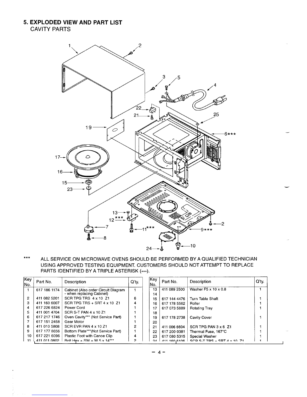
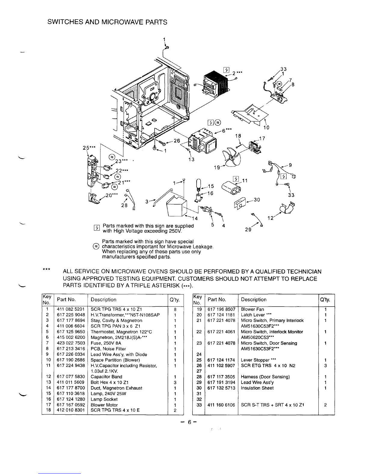
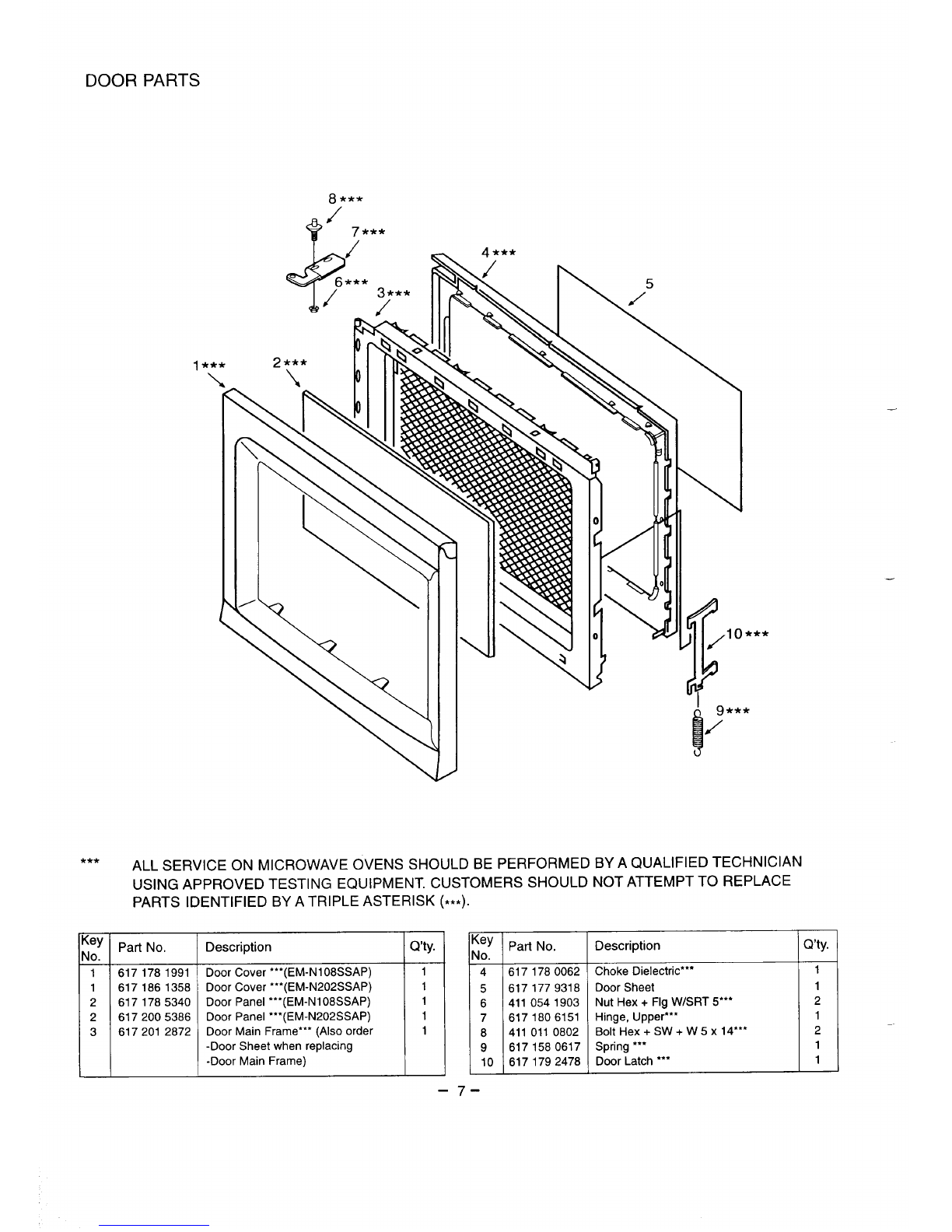
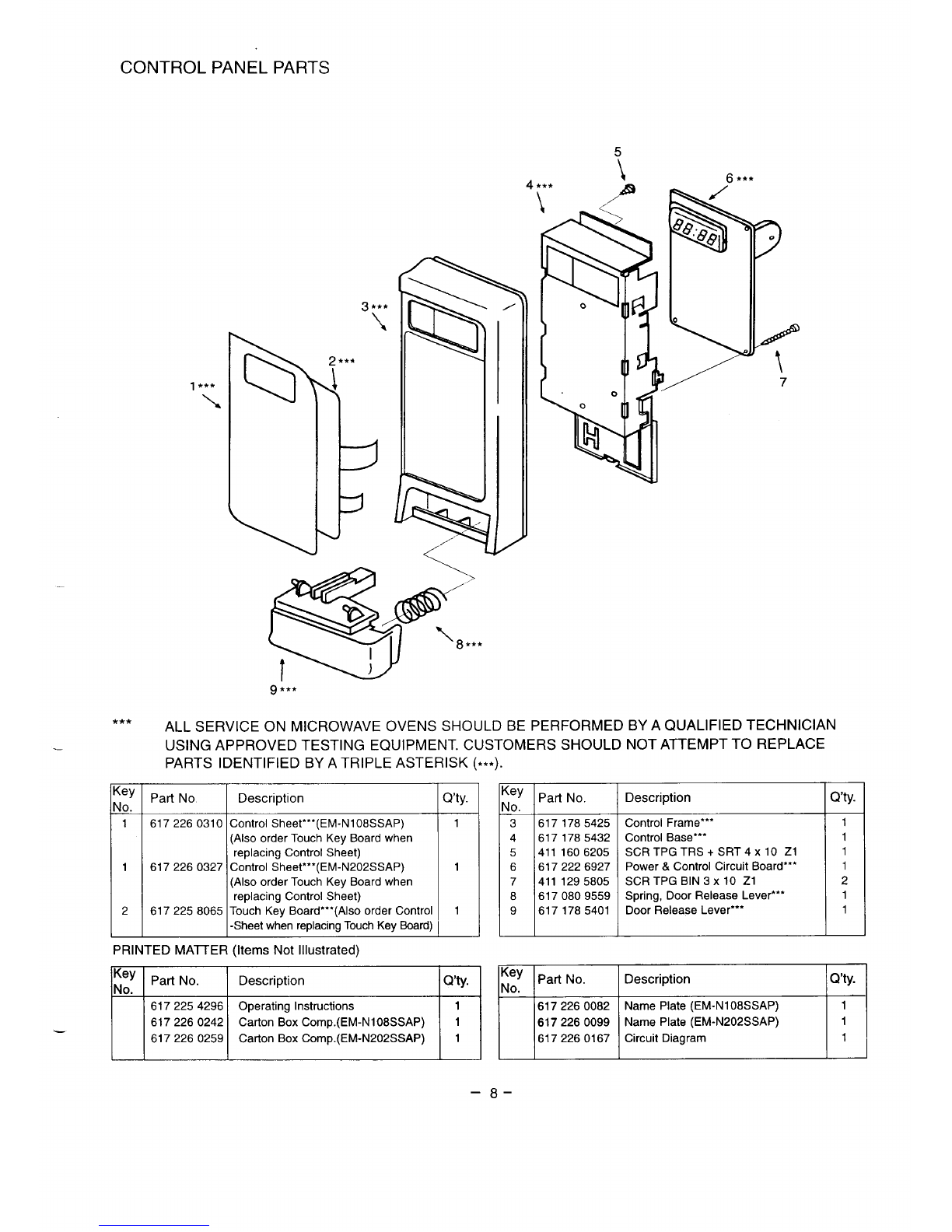
Power Output Measurement. ................. 1Exploded View and Parts List... . . . . . . . . . 5-10
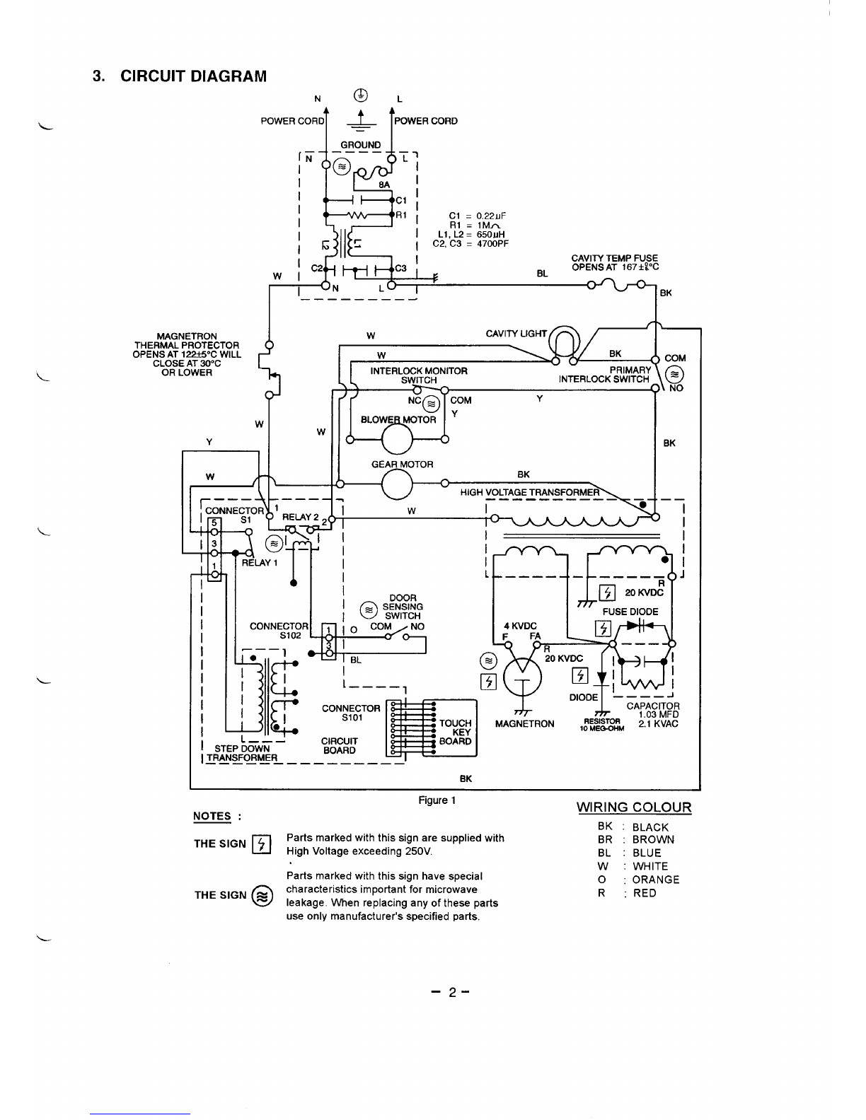
Circuit Diagram ............................ 2Overall Circuit Diagram ................ 11
1. SPECIFICATIONS
Rated Power Consumption . .
Microwave Output. .........
Frequency . . . . . . . . . . . . . . . .
Power Supply .............
Rated Current .............
Safety Devices . . . . . . . . . . . .
Timer ...................
Overall Dimensions. . . . . . . . .
Oven Cavity Size ..........
Turntable Diameter ........
Effective Capacity of
Oven Cavity . . . . . . . . . . . . . .
Net Weight ...............
1150W.
750 w.
2450MHzf50MHz.
230- 240V,50HZ.
5.1 Amp.
Temp. Fuse, Open
at 16TCforCavity.
Thermal Protector, Open
at 122’C for Magnetron.
Fuse (Cartridge Type 8A)
Primary Interlock Switch.
Door Sensing Switch and
Relay 2.
Interlock Monitor Switch.
Electronic Digital, up to
99 rein, 99 sec.
458(W) X351 (D) X250(H)
mm.
290 (W) X311(D) X191 (H)
mm.
275 mm.
17 liters.
Approx. 12.5 Kg.
2. POWER OUTPUT MEASUREMENT
NOTE
The Power Output specification 750Won this model is
measured with IEC measurement. The Power Output is
measured with two (2) liters water is equivalent to 750W in
measurement with IEC, when measured with the following
power output.
(A) 1. Fill two test bowls with each 1liter water respectively.
(c)
(D)
(E)
(F)
(G)
1.
2.
1.
2.
1.
2.
3.
Set cooking time to two (2) minutes. (“2 00 appears
in display)
Touch START key and operate oven for exactly two
(2) minutes.
Take out the two bowls at once.
Stir both water with thermometer and measure the
water temperature rise respectively.
Get temperature rise by calculation the difference
(water temperature after cooking minus initial
temperature) in each bowl.
Then calculate average value(t) of both temperature
rise in degrees centigrade.
Then work out;
Power Output (watt) =70 xAt
Where At is an Average Temperature Rise in degrees
centigrade. -
Power Output shall be in the following range:
Average Microwave
Temperature Rise Power Output
IMinimum
9.&c I672 WI
Maximum
12.WC 861 w
Power Output will be influenced by line voltage of
power supply. Consequently, correct power output
must be measured within 240V AC f2volt while unit
is operating.
2. Use accurate thermometer and measure each
water temperature respectively.
(B) Place the two bowls on glass turntable.
-1-
L
3. CIRCUIT DIAGRAM
,OWERCOJ ~(mm.
(T
I
I
I
I
I
I
IGROUND I
+—+ ++CI
1
I
I
I
MAGNE1730N
THERMALPROTECTOR
OPENS AT 1221S”CWILL
CLOSEAT30”C
OR LOWER !
w
i
I
ICl =0.22LJF
IL1,R;2=&O;H
1C2, C3 =4700PF
I————————-
w
wCAVITYLIGHT
w
INTERLOCKMONITOR PRIMARY
SWITCH INTERLOCKSWITCH
t
w’
GEAR MOTOR BK
uHIGHVOLTAGETRANSFORMER
7wI
I
BK
III
w
————
I
. I
————- ,— .—_— —— J
I
IFUSE DIODE
ICONNECTOR
IS102
I-—— 1
I●
c
I~I
II–_––,
I /
Ic
m
ICON&~;lTOR
I.1 TOUCH MAGNETRON RESISTOR
KEY 10MEQ-OHM 2.1 KVAC
ISTEPbOWN
——. CIRCUIT BOARD
ITRANSFORMER BOARD
————— ————————.
COM
@
\NO
BK
—— I
I
——.
IBK
NOTES :❑
THE SIGN j
o
THE SIGN ~
Figure 1WIRING COLOUR
BK :BLACK
Parts marked with this sign are supplied with BR :BROWN
High Voltage exceeding 250V. BL :BLUE
W:WHITE
Parts marked with this sign have special o:ORANGE
characteristics important for microwave R:RED
leakage. When replacing any of these parts
use only manufacturer’s specified parts.
-2-
4. TEST PROCEDURES
–3-
W
J
./
P“ Filament Windings
CAUTION
–DISCONNECT THE POWER SUPPLY CORD FROM
THE WALL OUTLET WHENEVER REMOVING THE
CABINET FROM THE UNIT. PROCEED WITH THE
TESTS ONLY AITER DISCHARGING THE HIGH
VOLTAGE CAPACITOR AND REMOVING THE LEAD
WIRES FROM THE PRIMARY WINDING OF THE
HIGH VOLTAGE TRANSFORMER. (SEE FIGURE 3)
A. TEST PROCEDURES
L.
L
L
L
Figure 3
-4-
5. EXPLODED VIEW AND PART LIST
CAVITY PARTS
***
-
***
:ey
Jo.
1
2
3
4
5
6
7
8
9
10
11
ALL SERVICE ON MICROWAVE OVENS SHOULD BE PERFORMED BY A QUALIFIED TECHNICIAN
USING APPROVED TESTING EQUIPMENT. CUSTOMERS SHOULD NOT ATTEMPT TO REPLACE
PARTS IDENTIFIED BY A TRIPLE ASTERISK (***).
Part No.
6171861174
4110825201
411 1606007
6172266824
4110014704
6172171746
6171512458
4110105808
6171778656
6172216096
411 nii nm9
Description
Cabinet (Also order Circuit Diagram
-when replacing Cabinet)
SCR TPG TRS 4X10 Z1
SCR TPG TRS +SRT 4X10 Z1
Power Cord
SCR S-T PAN 4X10 Z1
Oven Cavity’”’ (Not Service Part)
Gear Motor
SCR EVR PAN 4X10 Z1
Bottom Plate* ’*(Not Service Part)
Plastic Foot with Canoe Clip
Rnlt Hpx +.SW &W6Y1A*”
Yty.
1
6
4
1
1
1
1
2
1
4
9—
:ey
do.
13
14
15
16
17
18
19
20
21
22
23
9A
Part No.
4110892500
6171444476
6171785562
6170735889
8171782738
4110066604
6172000381
6170805315
A~~ iam,cinc
Description
Washer F5 x10 x 0.8
Turn Table Shaft
Roller
Rotating Tray
Cavity Cover
SCR TPG PAN3X6Z1
Thermal Fuse, 167°C
Special Washer
CPD C-TTRC .CRT A.4A 74
a’ty.
1
1
1
1
1
1
1
1
i
-4-
L
L
SWITCHES AND MICROWAVE PARTS
1
?
lba-
*
/. .
\
6●** 10
18
\-I 7
B*
/
1’3
19-
P
,‘>@’‘
‘“20’”‘A3-4,*I-%&& w’ Q’j
‘‘-%
-14 \f \1’”
131
@
Parts marked with this sign are supplied 54 #A
with High Voltage exceeding 250V.
Parts marked with this sign have special
characteristics important for Microwave Leakage,
When redacina anv of these Darts use onlv
manufacturers-speiified parts. .
*** ALL SERVICE ON MICROWAVE OVENS SHOULD BE PERFORMED BY A QUALIFIED TECHNICIAN
USING APPROVED TESTING EQUIPMENT. CUSTOMERS SHOULD NOT ATTEMPT TO REPLACE
PARTS IDENTIFIED BY A TRIPLE ASTERISK (***).
ley
to. Part No. Description Q’ty.
14110825201 SCR TPG TRS 4X10 Z1 8
26172259048 H.V.Transformer,’’* N5T-N108SAP 1
36171778694 Stay, Cavity &Magnetron 1
4411 0066604 SCR TPG PAN 3X6Z1 1
56171259650 Thermostat, Magnetron 122°C 1
64150026200 Magnetron, 2M218J(S)A-’** 1
74230227503 Fuse, 250V 8A 1
86172133416 PCB, Noise Filter 1
96172260334 Lead Wire Ass’y, with Diode 1
10 6171902686 Space Partition (Blower) 1
11 6172249438 H.V.Capacitor including Resistor, 1
1.03uf 2.1 KV.
12 6170775830 Capacitor Band 1
13 411 011 5609 Bolt Hex 4 x 10 Z1 3
14 6171778700 Duct, Magnetron Exhaust 1
15 6171103618 Lamp, 240V 25W 1
16 6171241280 Lamp Socket 1
17 6171670592 Blower Motor 1
18 4120108301 SCRTPGTRS4X1OE 2
;ey
Jo.
19
20
21
22
23
24
25
26
27
28
29
30
31
32
33
—
6-
Part No.
6171968507
6171241181
6172214078
6172214061
6172214078
6171241174
411 1025907
6171173505
6171913194
6171325713
4111606106
,-
Description
Blower Fan
Latch Lever **’
Micro Switch, Primary Interlock
AM51630C53F2”*
Micro Switch, Interlock Monitor
AM50620C53”*”
Micro Switch, Door Sensing
AM51630C53F2*”*
Lever Stopper **’
SCR ETG TRS 4X10 N2
Harness (Door Sensing)
Lead Wire Ass’y
Insulation Sheet
SCR S-TTRS +SRT 4X10 ZI
3’ty.
1
1
1
1
1
1
3
1
1
1
2
8...
%/7***
/
1***
***
(ey
10.
1
1
2
2
3
\,
,
\- 6
***
‘9***
!
/
ALL SERVICE ON MICROWAVE OVENS SHOULD BE PERFORMED BY A QUALIFIED TECHNICIAN
USING APPROVED TESTING EQUIPMENT. CUSTOMERS SHOULD NOT ATTEMPT TO REPLACE
PARTS IDENTIFIED BY A TRIPLE ASTERISK (***).
Part No.
6171781991
6171861358
6171785340
6172005386
6172012872
Description
Door Cover ●*’(EM-N1 08SSAP)
Door Cover *“’( EM-N202SSAP)
Door Panel “*(EM-N108SSAP)
Door Panel “*(EM-N202SSAP)
Door Main Frame*** (Also order
-Door Sheet when replacing
-Door Main Frame) 1[
Yty. Key
No.
14
15
16
17
18
9
10
Part No.
6171780062
6171779318
4110541903
6171806151
4110110802
6171580617
6171792478
Description
Choke Dielectric”*
Door Sheet
Nut Hex +Flg W/SRT 5***
Hinge, Upper***
Bolt Hex +SW+ W5 x 14***
Spring *’*
Door Latch ●*”
a’ty.
1
1
2
1
2
1
1
–7-
CONTROL PANEL PARTS
5
13,,,
***
[
Key
No.
1
1
2
3***
\
I
4*** \
\/s
\8,,.
9;**
I0
ALL SERVICE ON MICROWAVE OVENS SHOULD BE PERFORMED BY A QUALIFIED TECHNICIAN
USING APPROVED TESTING EQUIPMENT. CUSTOMERS SHOULD NOT ATTEMPT TO REPLACE
PARTS IDENTIFIED BY A TRIPLE ASTERISK (iii).
Part No
6172260310
6172260327
6172258065
Description
Control Sheet*’*( EM-N108SSAP)
(Also order Touch Key Board when
replacing Control Sheet)
Control Sheet””=(EM-N202SSAP)
(Also order Touch Key Board when
replacing Control Sheet)
Touch Key Board”g*(Also order Control
-Sheet when replacingTouch Key Board)
Q’ty.
1
1
1
3 6171785425
4 6171785432
5 4111606205
6 6172226927
7 4111295805
86170809559
9 6171785401
PRINTED MAITER (Items Not Illustrated)
‘ey Part No. Description
.E
‘ey Part No.
No. Q’ty. No
6172254296 Operating Instructions 16172260082
6172260242 Carton Box Comp.(EM-Nl 08SSAP) 16172260099
6172260259 Carton Box Comp.(EM-N202SSAP) 1 6172260167
–8-
Description Q’ty.
Control Frame””’ 1
Control Base’”” 1
SCR TPG TRS +SRT 4X10 Z1 1
Power &Control Circuit Board*** 1
SCR TPG BIN 3X10 Z1 2
Spring, Door Release Lever*** 1
Door Release Lever”** 1
Description Q’ty.
Name Plate (EM-N108SSAP) 1
Name Plate (EM-N202SSAP) 1
Circuit Diagram 1
I
CONTROL CIRCUIT BOARD
(%tl NO. 617222 6927)
o–K&C SS4594V -OLCD1
——— ——— ——_ ———
LL–, 0
.—— ——— ___ ——. _
II I
TP-1
~GROUND
TP-2
-9-
CONTROL CIRCUIT BOARD
(Part NO. 617222 6927)
L
L
L
L
Key No. Order Part No, Description Q’ty
INTEGRATEDCIRCUIT.
Icll 4094660209 IC LM8847B-1A43 1
1II
TRANSISTORS
QIO1, 105
QI 04
QI02, 103
DIODES.
Dll
D1OI-106
ZD11
ZD1OI
CAPACITOR:
CI04, 105
108, 109
C103, 106,
107
Clol
C12
Cll
4050824619
4050354819
4050001812
4070120220
4070124426
4070568517
4071322316
4030691247
4031425326
4030492616
4031053816
4031527218
DTA123YS-TP
2SC 1685-Q-TP
DTA143XS-TP
1N4002-TP
1SS133-TP
RD5,1ESB2
HZS3.9NB2
Ceramic,1000PK,
+-5%, 50V,
Ceramic,0.01mfd,
+-50/.,50V.
ElectrolyUc, 1mfd,
+-20%, 50V.
Electrolytic, 47mfd,
+-20%, 1Ov.
Electrolytic, 1000mfd,
+-20”A, 25V.
2
1
2
1
6
1
1
4
3
1
1
1
Key No. Order Pari No. Description Q’ty
RESISTORS
R108
R1OI, 115
R102, 113,
122-128
Rll -14
R56
RI06, 127
R109, 110
Rlll
RI14
R52
R104, 112,
116-121
R103,1O5
R107
4010124434
4010125639
4010126953
4010134156
4010136338
4010164757
4010169653
4010182751
4010183738
4010184834
4010201957
4010202835
4010231637
RESISTORS BLOCKS
Carbon, 100 ohms
+-5%, ~14vJ.
Carbon, 1Kohms
+-50A, ~14W.
Carbon, IOK ohms
+-5%, l/4w.
Carbon, 120 ohms
+-5%, 114W,
Carbon, 12K ohms
+-5%, J14W.
Carbon, 22K ohms
+-5%, J14W.
Carbon, 27 ohms
+-5%, 714W,
Carbon, 330 ohms
+-5%, 7/4w.
Carbon,3.3K ohms
+-5%, ~14w.
Carbon, 33K ohms
+-5%, 714W.
Carbon, 4,7K onms
+-5%, 714W.
Carbon, 47K ohms
+-5%, 114W.
Carbon, 820 ohms
+-5%, J14W.
1
2
7
4
1
2
2
1
1
1
8
2
1
RBIO1 8170103558 Resistor Network 1
MISCELLANEOUS.
BZ1
VST1
LCD1
RL1
RL2
RS1
SI
Slol
SI02
PT1
2
JB1,2
J3, 5,8,
9, 12-17
J101-102
4200006800
4071185505
6172092218
6172013978
6171410549
6171283372
6171694109
6171268959
617111 1392
6171712155
6171784268
6171325744
6170794299
6170794237
Buzzer, PKM22EPT
Varistor ENC 471 D-IOA.
Display Tube.
Relay, G5N-IA-DC12.
Relay, Du12D1-PR
Ceramic Oscillator
Connector.
Connector,l 1P
Connector, 2/3P, Male.
Step-Down Transformer,
PD5TK-S150
Part Base
Noise Filter
Jumper.
Jumper.
1
1
1
1
1
1
1
1
1
1
1
2
10
2
-1o-
6. OVERALL CIRCUIT DIAGRAM
———— ———— ———— —-—— ——— — — —.
—
‘[7
I
I
I
I
L
i
,-
>‘
,
L
I
I
1. I
L__———_——— --_-L ——_.
----- I
u
<
SANYO Electric Co., Ltd.
Osaka, Japan
AUGUST ‘99/300 LT Printed in Singapore
-11-

This manual suits for next models

1

Other Sanyo Microwave Oven manuals

Sanyo EM-M105 User manual

Sanyo

Sanyo EM-M105 User manual

Sanyo EM607TW User manual

Sanyo

Sanyo EM607TW User manual

Sanyo EMO-SRT10SG User manual

Sanyo

Sanyo EMO-SRT10SG User manual

Sanyo EM-SL50GRILL User manual

Sanyo

Sanyo EM-SL50GRILL User manual

Sanyo EM-C2000 User manual

Sanyo

Sanyo EM-C2000 User manual

Sanyo EM-607T Use and care manual

Sanyo

Sanyo EM-607T Use and care manual

Sanyo EM-Z2100GS - 8 Cubic Foot Microwave Use and care manual

Sanyo

Sanyo EM-Z2100GS - 8 Cubic Foot Microwave Use and care manual

Sanyo SM-GA0005 User manual

Sanyo

Sanyo SM-GA0005 User manual

Sanyo EM-X680S User manual

Sanyo

Sanyo EM-X680S User manual

Sanyo EM-V3405SW User manual

Sanyo

Sanyo EM-V3405SW User manual

Sanyo EMC 1100 User manual

Sanyo

Sanyo EMC 1100 User manual

Sanyo EM-C6786V - Microwave Oven With Convection Use and care manual

Sanyo

Sanyo EM-C6786V - Microwave Oven With Convection Use and care manual

Sanyo EM-Z2100GS - 8 Cubic Foot Microwave Use and care manual

Sanyo

Sanyo EM-Z2100GS - 8 Cubic Foot Microwave Use and care manual

Sanyo EM-S105AW User manual

Sanyo

Sanyo EM-S105AW User manual

Sanyo EMS5120W - 1.2 Cubic Foot Capacity 1000 Watt Countertop... User manual

Sanyo

Sanyo EMS5120W - 1.2 Cubic Foot Capacity 1000 Watt Countertop... User manual

Sanyo EM-X690S User manual

Sanyo

Sanyo EM-X690S User manual

Sanyo EMX-412 User manual

Sanyo

Sanyo EMX-412 User manual

Sanyo EM-G450 User manual

Sanyo

Sanyo EM-G450 User manual

Sanyo EM-X470S User manual

Sanyo

Sanyo EM-X470S User manual

Sanyo EM-C950 User manual

Sanyo

Sanyo EM-C950 User manual

Sanyo EM-C1100UK User manual

Sanyo

Sanyo EM-C1100UK User manual

Sanyo EM-S1577W User manual

Sanyo

Sanyo EM-S1577W User manual

Sanyo EM-X4111 User manual

Sanyo

Sanyo EM-X4111 User manual

Sanyo EM-S1563 User manual

Sanyo

Sanyo EM-S1563 User manual

Popular Microwave Oven manuals by other brands

Neue NEG440X User instructions

Neue

Neue NEG440X User instructions

SEVERIN MW 7873 Instructions for use

SEVERIN

SEVERIN MW 7873 Instructions for use

ETNA CM250 Series Instructions for use

ETNA

ETNA CM250 Series Instructions for use

Whirlpool MH3184XPS Dimensions

Whirlpool

Whirlpool MH3184XPS Dimensions

Frigidaire GLMV168C Factory parts catalog

Frigidaire

Frigidaire GLMV168C Factory parts catalog

Pelgrim OM540MAT/P03 Instructions for use

Pelgrim

Pelgrim OM540MAT/P03 Instructions for use

Beko BMGB 25332 BG user manual

Beko

Beko BMGB 25332 BG user manual

Haier HWO38MG4HXBD user manual

Haier

Haier HWO38MG4HXBD user manual

Sharp R-671 Operation manual with cookbook

Sharp

Sharp R-671 Operation manual with cookbook

Defy DMO 336 owner's manual

Defy

Defy DMO 336 owner's manual

AmazonBasics S9N29R Service manual

AmazonBasics

AmazonBasics S9N29R Service manual

Wolf MW24 Use & care guide

Wolf

Wolf MW24 Use & care guide

GE RVM5160MPSA installation instructions

GE

GE RVM5160MPSA installation instructions

Samsung GE614ST Owner's instructions and cooking guide

Samsung

Samsung GE614ST Owner's instructions and cooking guide

Frigidaire FFCE1431LB Manuel d’utilisation et d’entretien

Frigidaire

Frigidaire FFCE1431LB Manuel d’utilisation et d’entretien

Samsung MS23K3555 series user manual

Samsung

Samsung MS23K3555 series user manual

Frigidaire FFCE2238LB Manual de uso y cuidado

Frigidaire

Frigidaire FFCE2238LB Manual de uso y cuidado

Culina UBMICROL20SS instruction manual

Culina

Culina UBMICROL20SS instruction manual

manuals.online logo
manuals.online logoBrands
  • About & Mission
  • Contact us
  • Privacy Policy
  • Terms and Conditions

Copyright 2025 Manuals.Online. All Rights Reserved.