Sanyo PLV-55WHD1 User manual

FILE NO.
SERVICE MANUAL
LCD Projection TV
REFERENCE NO. SM5110797-00
PRODUCT CODE :
PLV-55WHD1 M8LA 1 122 293 00
PLV-65WHD1 M8PA 1 122 364 00
Original Version MODEL NO. PLV-55WHD1
PLV-65WHD1
U.S.A.
Chassis No. M8L-55WHD100
M8P-65WHD100
NOTE: Match the Chassis No. on the rating
sheet on the cabinet with the
Chassis No. in the Service Manual.
If the Original Version Service
Manual Chassis No. does not
match the unites, additional
Service Literature is required. You
must refer to “Notices” to the
Original Service Manual prior to
servicing the unit.
Give complete “CHASSIS NO." for parts order
or servicing, it is shown on the rating sheet on
the cabinet of the LCD Projection TV.

■Contents.................................................................................................................2
■Safety Instructions..................................................................................................3
■Specifications .........................................................................................................4
■Circuit Protections ..................................................................................................5
■Installation ..............................................................................................................7
■Cleaning ...............................................................................................................10
■Lamp Replacement ..............................................................................................12
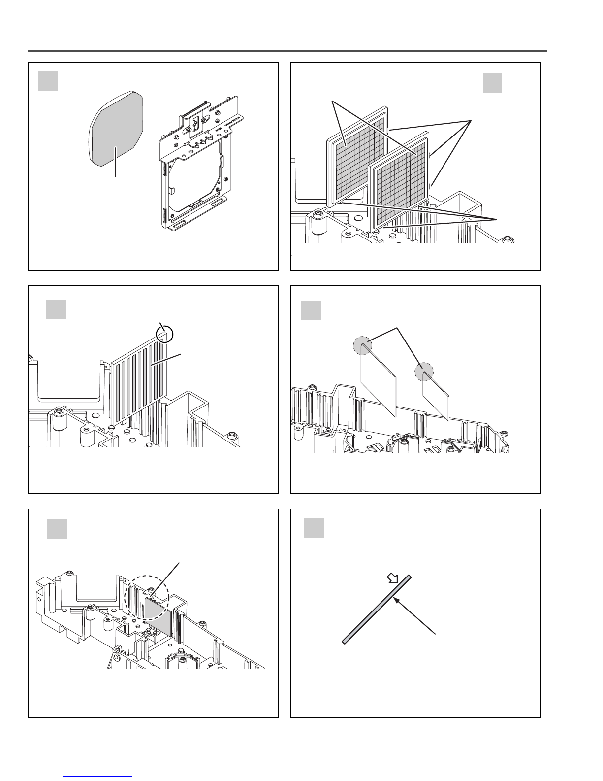
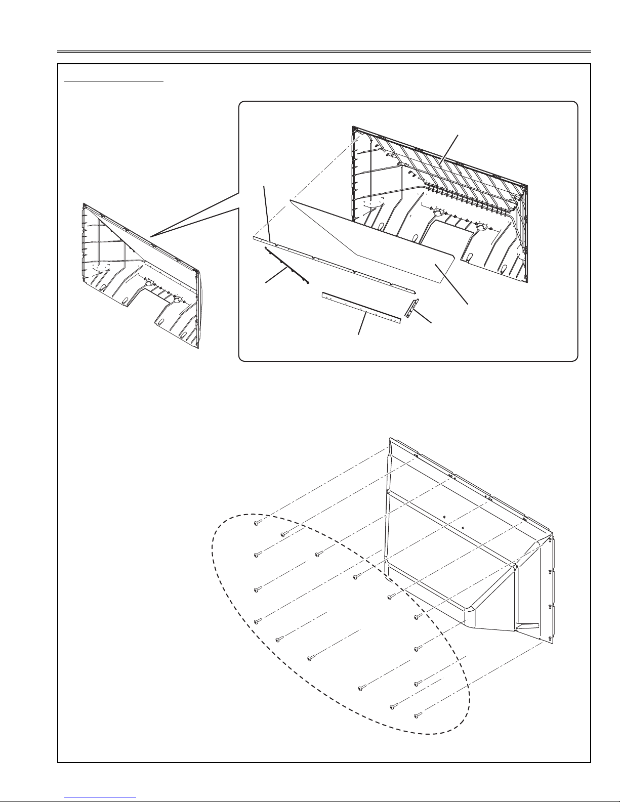
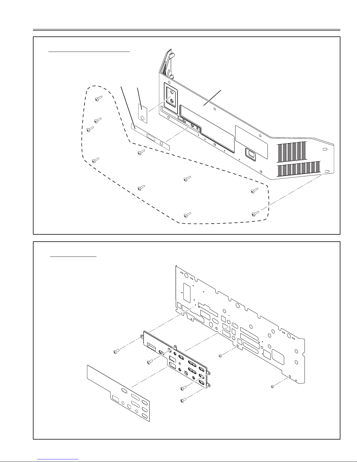
■Mechanical Disassemblies...................................................................................15
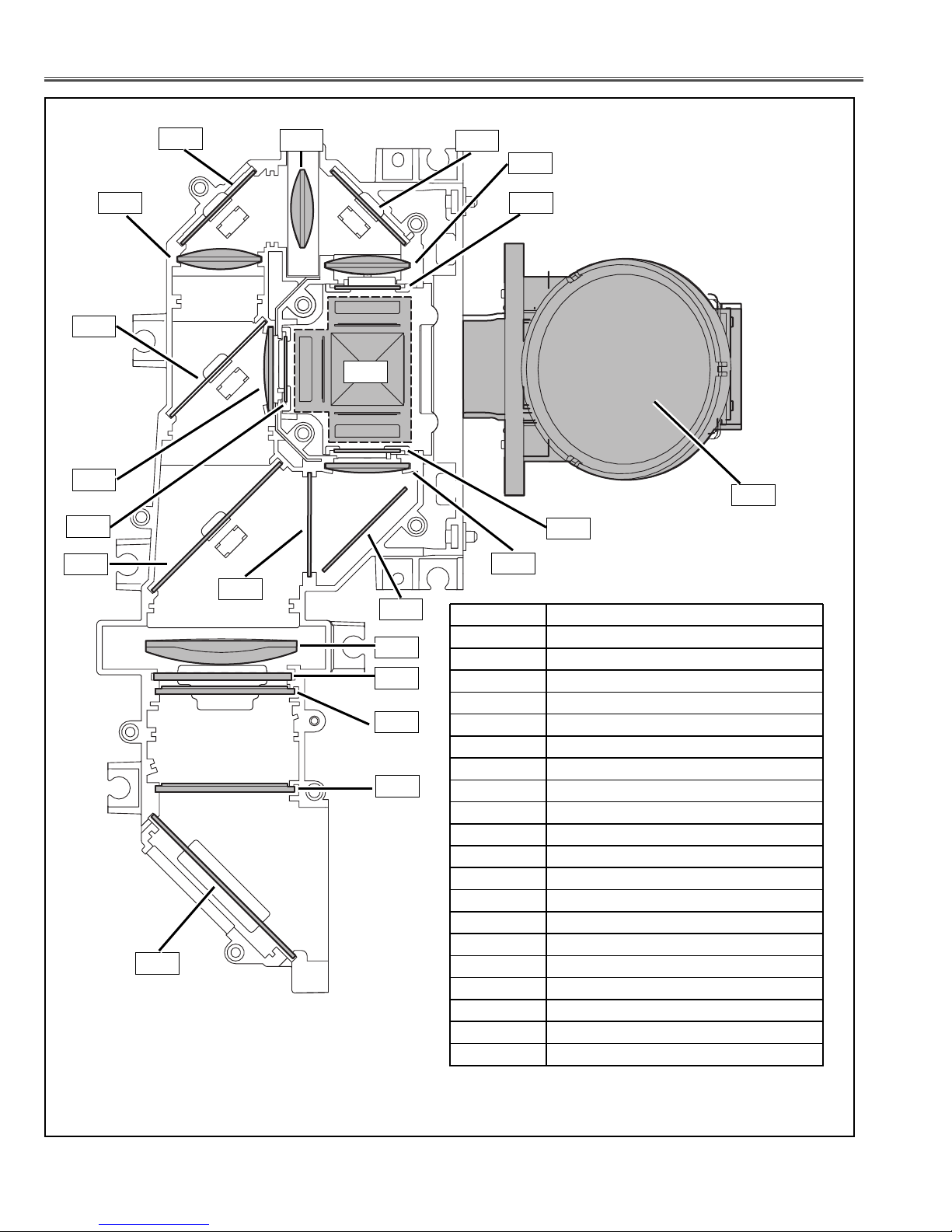
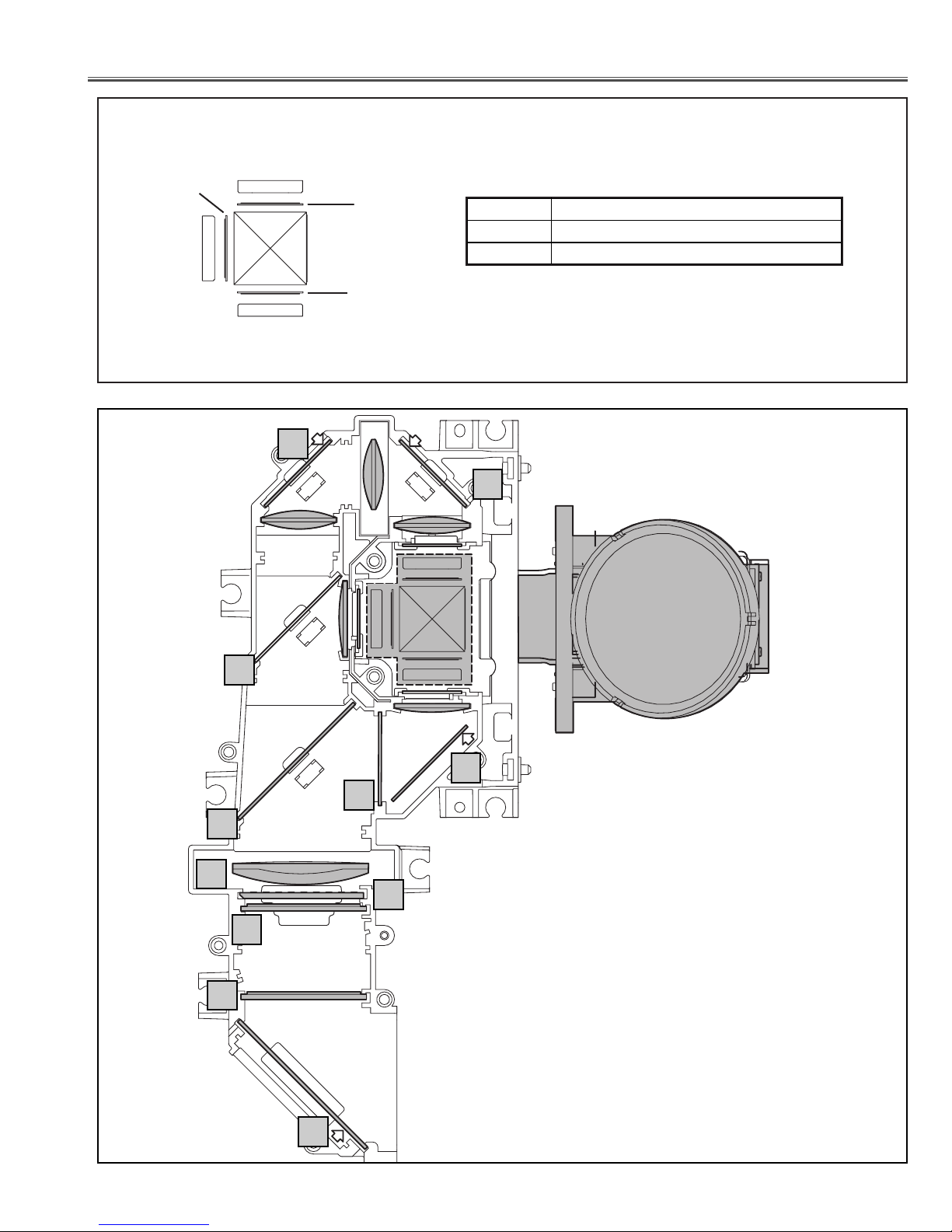
■Optical Parts Location and Direction....................................................................54
■Adjustments after Parts Replacement .................................................................58
■Optical Adjustments .............................................................................................59
■Electrical Adjustments..........................................................................................72
●Service Adjustment Menu Operation..........................................................72
●Circuit Adjustments .....................................................................................73
●Service Adjustment Data Table...................................................................77
●Test Points Location ...................................................................................84
■Chassis Block Diagrams ......................................................................................85
■Power Supply Lines..............................................................................................94
■Troubleshooting ....................................................................................................95
■Control Port Functions .........................................................................................98
■Waveforms..........................................................................................................100
■IC Block Diagrams .............................................................................................101
■Service Parts List ...............................................................................................106
■Mechanical and Optical Parts List ............................................................106
■Electrical Parts List ...................................................................................123
■Appendix ............................................................................................................148
●Quick Reference of Chassis Disassemblies .............................................148
--------------------------------------------------------------------------------------------------------------------
Drawings & Diagrams .......................................................................... A1 - A15
■Parts description and reading in schematic diagram .......................................... A2
■Schematic Diagrams ....................................................................................A3 - A8
■Printed Wiring Board Diagrams ................................................................ A9 - A14
■Pins description of ICs, transistors, diodes ...................................................... A15
Note: "PTV" may be used as an abbreviation for LCD Projection TV in this manual.
- 2 -
■Contents

KEY No. DESCRIPTION
201 ASSY PRISM (PBS)
202 ASSY LCD PANEL/PRISM
203 LENS CONDENSER (G)
204 LENS CONDENSER (R)
205 LENS CONDENSER (B)
206 LENS RELAY (OUT)
207 LENS RELAY (IN)
208 LENS CONDENSER (OUT)
209 LENS INTEGRATOR
210 LENS INTEGRATOR(OUT-UV)
211 LENS PROJECTION
212 MIRROR (B)
213 MIRROR (R)
214 MIRROR (W)
215 OPTICAL FILTER (B)
216 POLARIZED GLASS (IN/R)DF
217 POLARIZED GLASS (IN/G)
218 POLARIZED GLASS (IN/B)
219 DICHROIC MIRROR (B)
220 DICHROIC MIRROR (G)
201
210
209
212
214
208
211
204
216
213 213
207
220
218
205
203
217
219
215
206
202
- 54 -
■Optical Parts Location and Direction

202-3 POLARIZED GLASS (OUT/B)
202-1
R
G
B
202-3
202-2
202-1 POLARIZED GLASS (OUT/R)
202-2 POLARIZED GLASS (OUT/G)
202 ASSY, LCD PANEL/PRISM
A
B
C
D
E
G
G
G
G
D
B
- 55 -
Optical parts location and direction

MIRROR
The marker comes
this surface side.
Reflective surface
G
Chamfer corner comes
this side up
OPTICAL FILTER (B)
Flat surface side
comes this side.
Film attached side
comes this side.
Chamfer corner comes
this side.
CONDENSER LENS (OUT)
PBS
Rugged surface side
comes this side/
Convex part
Convex
part
INTEGRATOR LENS
Chamfer conner comes
this side up.
DICHROIC MIRROR
AB
CD
E
- 56 -
Optical parts location and direction

Printed marker comes
this side.
Optical filter (LENTI) comes this side.
(Black surface screen comes this side.)
Film side
Film side Polarized glass
Film attached side
comes this side
(LCD panel side)
POLARIZED GLASS(IN)
Film attached side
comes this side.
H
IJ
- 57 -
Optical parts location and direction

Note:
Part order must contain Model No., Chassis No., Part No., and descriptions.
Give complete “Chassis No." for parts order or servicing, it is shown on the rating sheet on the cabinet(rear side) of
the LCD projection TV.
Mechanical and Optical parts
See Model No. and Chassis No.
- 106 -
A: Cabinet back Unit
C: Cabinet bottom cover unit
D: AV panel unit
E: DIgital tuner unit
F: Front cover unit
G: R-side grille KEY unit
H: L-side grille unit
I: Cabinet bottom unit
J: Front panel unit
K: Optical / chassis unit
B: Cabinet front Unit
Fig. PL01
■Mechanical and Optical Parts List■Service Parts List

A: Cabinet back Unit
- 107 -
Mechanical and Optical parts list
8
28
30
29
31
3
S1x16
Fig. PL02-a
Fig. PL02-b

- 108 -
Mechanical and Optical parts list
B: Cabinet front Unit
27
25
26
27
2
7
45
S1
S1
S1
S1
Fig. PL03-a
Fig. PL03-b

- 109 -
Mechanical and Optical parts list
C: Cabinet bottom cover unit
D: AV panel unit
S1 x 10
9
23
21
34
36
36
38
16
S2
S2
S2
S2
Fig. PL04
Fig. PL05

17
18
24 41
41
41
41 42 42
42
42
S3
S3
S3
S3
S3
S3
S3
S3
F: Front cover unit
- 110 -
Mechanical and Optical parts list
E: DIgital tuner unit
51
109
117
69
Fig. PL06
Fig. PL07

- 111 -
Mechanical and Optical parts list
G: R-side grille KEY unit
S4x4
S4x4
S4x4
H: L-side grille unit
5
55
58
11
12
22
6
6
43
43
35
35
33
32
S4x4
Fig. PL08
Fig. PL09

- 112 -
Mechanical and Optical parts list
I: Cabinet bottom unit
64
64
63
154
10
44
63
60
60
60
60
60
60
J: Front panel unit 39
14
4
40
40 15
13
20
44
44
44
19
37
Fig. PL10
Fig. PL11

- 113 -
Mechanical and Optical parts list
K: Optical / chassis unit
L: AV board unit
M: Duct & Main unit
N: Power unit
P: Optical unit
O: Optical duct unit
L: AV board unit
62
56
Fig. PL12
Fig. PL13

- 114 -
Mechanical and Optical parts list
M: Duct & Main unit 53
52
59
110
118
Fig. PL14-a
Fig. PL14-b

- 115 -
Mechanical and Optical parts list
N: Power unit
O: Optical duct unit 101
94
99
98
68
66
67
65
79
77
77
78 74
74
97
103
95
105
93
103
102
Fig. PL15
Fig. PL16

- 116 -
Mechanical and Optical parts list
Condenser lens unit
P: Optical unit
Relay lens unit
82
81
84
83
208
206
S5x2
S5x2
S6x4
S6x4
Fig. PL17
Fig. PL18

- 117 -
Mechanical and Optical parts list
Blue
Red
Green
Polarized glass (IN) unit
Red
Green Blue
76
216
217 218
76
76
S5 S5
S5
Fig. PL19-a
Fig. PL19-b

- 118 -
Mechanical and Optical parts list
Green
Red Blue
LCD panel/Prism assy
Projection lens unit
201-3
201-2
211
S8
S8
75
75
86
86
85
87
90
S8
S8
201-4
201-4
201-4
S7x4
201
201-1
Fig. PL20
Fig. PL21

- 119 -
Mechanical and Optical parts list
Optical base unit
92
91
96
96x4
89
107
106
Fig. PL22
Other manuals for PLV-55WHD1
2
This manual suits for next models
1
Table of contents
Other Sanyo Projection TV manuals
Popular Projection TV manuals by other brands

Sony
Sony KP-57WV600 - 57"hi-scan 1080i 16:9 Projection... operating instructions

Toshiba
Toshiba P503DL Service manual

Philips
Philips 50PL9126D/37E user manual

Philips
Philips Magnavox 9P6040C Specification sheet

Panasonic
Panasonic PT-47WX42 operating instructions

Toshiba
Toshiba ColorStream TP50G60 owner's manual