Table of Contents Assembly Tools Required
3-4
5-6
4-42
43-47
48-52
53-54
55
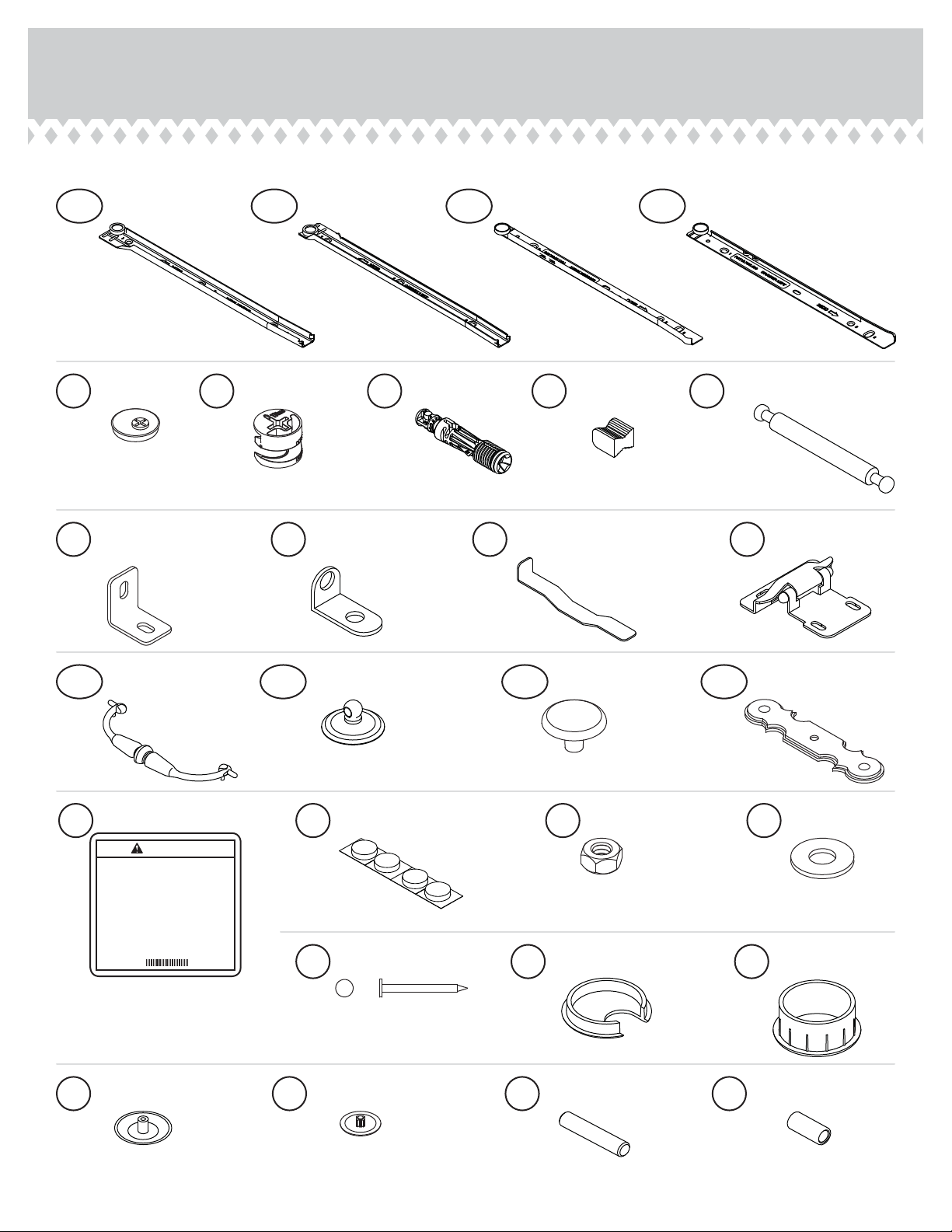
Part Identification
Hardware Identification
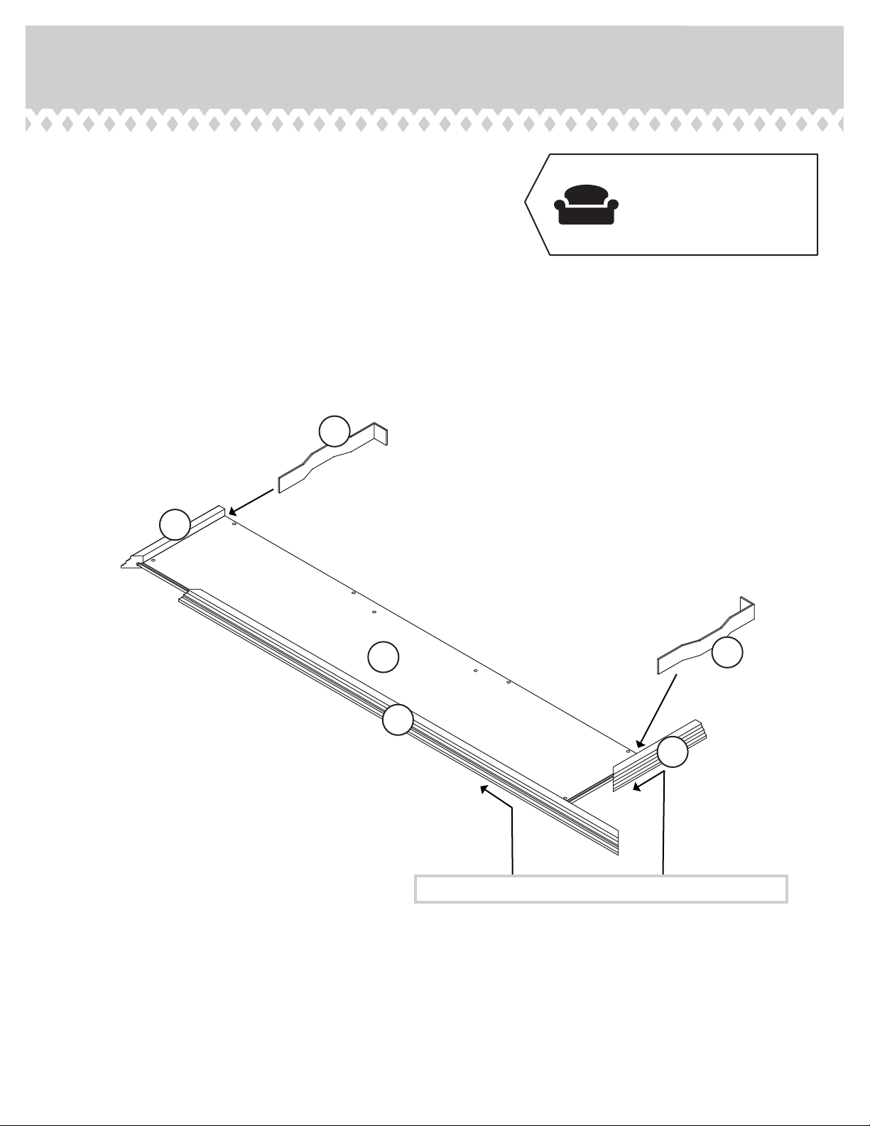
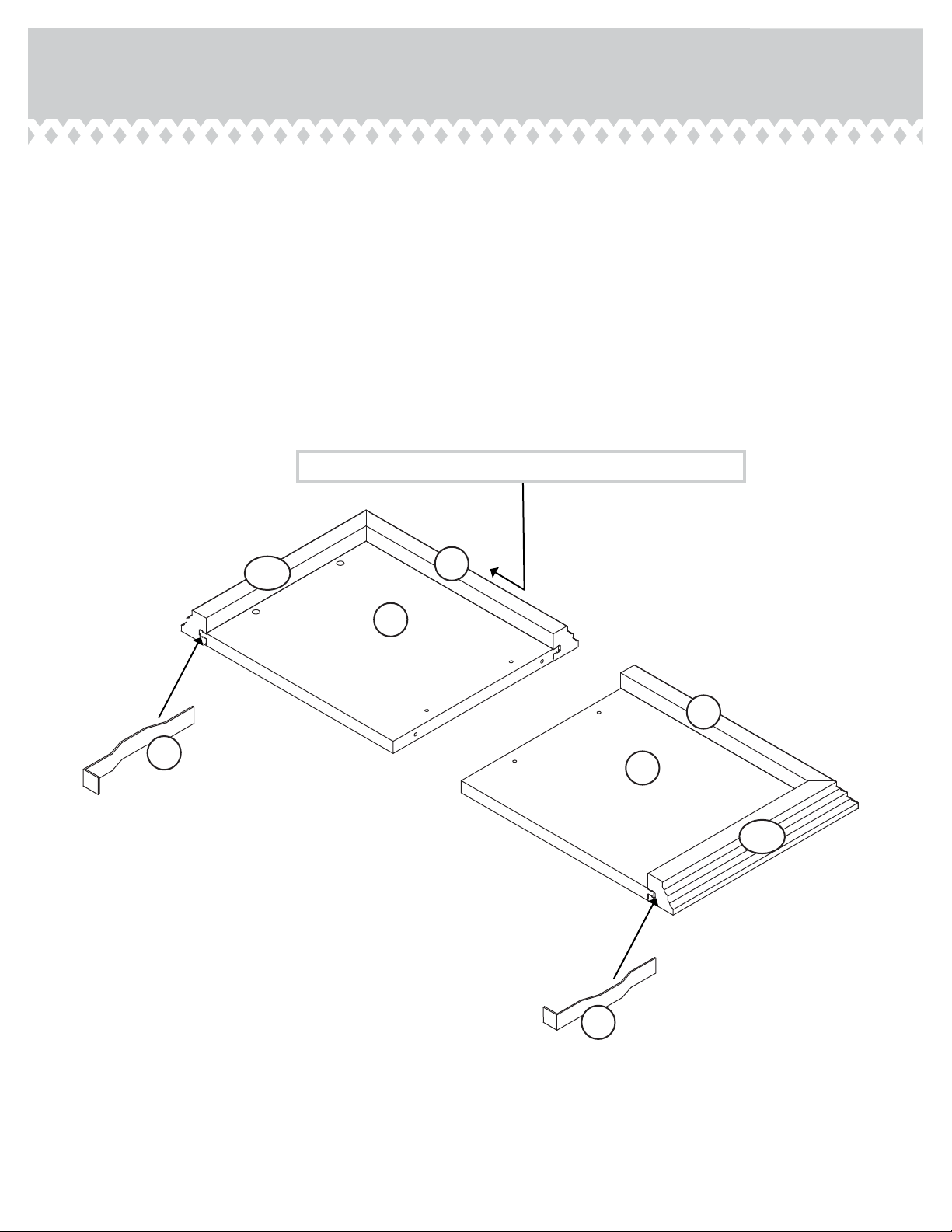
Assembly Steps
Français
Español
Safety
Warranty
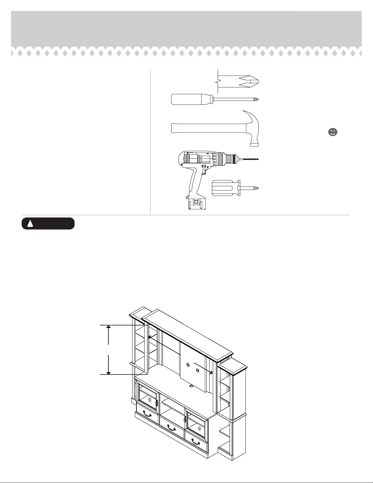
Hammer
Not actual size
No. 2 Phillips Screwdriver
Tip Shown Actual Size
Use of a TV that is too heavy or large is hazardous. A TV that is too heavy will create a risk of a tip-over that can cause severe injury or
death. A TV that is too large for the available space might be accidentally pushed or bumped o the furniture, or subject to tip-over.
• Check the size and weight of your TV. Compare it to the diagram below – before you begin assembly!
• This Sauder unit is designed for use with televisions weighing less than 95 pounds. Never use with a TV that weighs more.
• The size of the television, front-to-back and side-to-side, must fit within the space defined in the diagram.
• Never place the front edge of the TV past the front edge of the TV support shelf (or stop molding – if equipped)
• Never allow the sides of the TV to extend past the side edges of the TV support surface.
• If the TV has a CRT picture tube, the picture tube cone may extend past the rear of the support shelf.
• Be sure to apply the warning label as instructed in the last assembly step. The label provides important safety related information.
WARNING
!
95 lbs.
52"
418653 www.sauder.com/servicesPage 2
34-1/2"
Electric drill with 3/8" bit
(ONLY in indicated step)
Short Phillips Screwdriver