Schaub Lorenz SL0021KO User manual

SERVICE MANUAL
Design and specifications are subject to change without notice.
COLORTELEVISION/VIDEO CASSETTE RECORDER
SL0021KO
ORIGINAL
MFR’S VERSION A

CONTENTS
SERVICING NOTICES ON CHECKING.....................................................................................
HOW TO ORDER PARTS ..........................................................................................................
CONTENTS .................................................................................................................................
GENERAL SPECIFICATIONS....................................................................................................
DISASSEMBLY INSTRUCTIONS
1. REMOVAL OF MECHANICAL PARTS AND P. C. BOARDS............................................
2. REMOVAL OF DECK PARTS............................................................................................
3. REMOVAL OF ANODE CAP..............................................................................................
4. REMOVAL AND INSTALLATION OF FLAT PACKAGE IC ...............................................
KEY TO ABBREVIATIONS ........................................................................................................
SERVICE MODE LIST ................................................................................................................
PREVENTIVE CHECKS AND SERVICE INTERVALS..............................................................
WHEN REPLACING EEPROM (MEMORY) IC ..........................................................................
SERVICING FIXTURES AND TOOLS .......................................................................................
PREPARATION FOR SERVICING.............................................................................................
MECHANICAL ADJUSTMENTS ................................................................................................
ELECTRICAL ADJUSTMENTS..................................................................................................
BLOCK DIAGRAMS
TV ............................................................................................................................................
Y/C/AUDIO/HEAD AMP/21PIN/IN/OUT..................................................................................
MICON/JACK/LED..................................................................................................................
T' TEXT...................................................................................................................................
PRINTED CIRCUIT BOARDS
MAIN/CRT/POWER SW ..........................................................................................................
OPERATION/DECK.................................................................................................................
SYSCON..................................................................................................................................
SCHEMATIC DIAGRAMS
Y/C/AUDIO/HEAD AMP ..........................................................................................................
MICON .....................................................................................................................................
POWER ...................................................................................................................................
21PIN/IN/OUT..........................................................................................................................
CHROMA/IF.............................................................................................................................
SOUND AMP ...........................................................................................................................
T' TEXT ....................................................................................................................................
TV POWER..............................................................................................................................
DEFLECTION ..........................................................................................................................
CRT..........................................................................................................................................
JACK/LED................................................................................................................................
DECK.......................................................................................................................................
INTERCONNECTION DIAGRAM ...............................................................................................
WAVEFORMS .............................................................................................................................
MECHANICAL EXPLODED VIEWS...........................................................................................
CHASSIS EXPLODED VIEWS ...................................................................................................
MECHANICAL REPLACEMENT PARTS LIST .........................................................................
CHASSIS REPLACEMENT PARTS LIST..................................................................................
ELECTRICAL REPLACEMENT PARTS LIST...........................................................................
A1-1
A1-1
A2-1
A3-1~A3-5
B1-1, B1-2
B2-1~B2-5
B3-1
B4-1, B4-2
C1-1, C1-2
C2-1
C3-1, C3-2
C4-1
C5-1
C5-2
D1-1~D1-4
D2-1~D2-7
E-1, E-2
E-3, E-4
E-5, E-6
E-7, E-8
F-1, F-2
F-3, F-4
F-5~F-8
G-1, G-2
G-3, G-4
G-5, G-6
G-7, G-8
G-9, G-10
G-11, G-12
G-13, G-14
G-15, G-16
G-17, G-18
G-19, G-20
G-21, G-22
G-23, G-24
G-25, G-26
H-1~H-4
I-1, I-2
I-3, I-4
J1-1
J2-1
J3-1~J3-3
A2-1

GENERAL SPECIFICATIONS
G-1 TV CRT CRT Size / Visual Size 21 inch / 508.0mmV
System CRT Type Normal
Deflection 90 degree
Magnetic Field BV/BH +0.45G/0.18G
Color System PAL
Speaker 1Speaker
Position Front
Size 3 Inch
Impedance 8 ohm
Sound Output MAX 2.5W
10%(Typical) 2.0W
G-2 VCR System VHS
System Player / Recorder
Video System PAL
Hi-Fi STEREO No
NTSC PB(PAL60Hz) Yes
Deck DECK OVD-6S
Loading System Front
Motor 3
Heads Video Head 2 Head
FM Audio Head No
Audio /Control Mono / Yes
Erase(Full Track Erase) Yes
Tape Rec PAL/SECAM SP
Speed NTSC -
Play PAL SP
NTSC SP
Fast Forward / Rewind Time (Approx.) FF:1'48"/REW:1'48"
Cassette at E-180
Forward/Reverse NTSC or PAL-M SP=3x,5x
Picture Search PAL or SECAM SP=5x,7x
Frame Advance 1/10
Slow Speed 1/5~1/30
G-3 Tuning Broadcasting System CCIR+Italy System B/G
System Tuner and System 1Tuner
Receive CH Destination Oscar(W/HYPER)
Tuning System F-Synth
Input Impedance VHF/UHF 75 ohm
CH Coverage E2~E4, X~Z+2, S1~S10,
E5~E12,S11~S41,E21~E69
Intermediate Frequency Picture(FP) 38.9MHz
Sound(FS) 33.4MHz
FP-FS 5.5MHz
Preset CH 80CH
Stereo/Dual TV Sound No
G-4 Signal Video Signal Input Level 1 V p-p/75 ohm
Output Level 1 V p-p/75 ohm
S/N Ratio (Weighted) 53 dB
Horizontal Resolution at SP Mode 240 Lines
Audio Signal Input Level -3.8dB/50Kohm
Output Level -3.8dB/1Kohm
S/N Ratio at SP 42 dB
Harmonic Distortion (1KHz) 1.5 %
Frequency Response at SP 100Hz ~10kHz
at LP -
at SLP -
Hi-Fi Audio Signal Dynamic Range : More than -
Wow And Flutter : Less than -
Channel Separation : More than -
Harmonic Distortion : Less than -
G-5 Power Power Source AC 230V 50Hz
DC -
Power Consumption at AC 65 W at 230 V 50 Hz
A3-1

GENERAL SPECIFICATIONS
at DC -
Stand by (at AC) 6 W at 230 V 50 Hz
Per Year -
Protector Power Fuse Yes
Dew Sensor No
G-6 Regulation Safety CE
Radiation CE
X-Radiation -
G-7 Temperature Operation +5oC ~ +40oC
Storage -20oC ~ +60oC
G-8 Operating Humidity Less then 80% RH
G-9 On Screen Menu Yes
Display Menu Type Character
ATS No
Timer Rec Set Yes
Channel Setup Yes
Auto Tuning Yes
Ch Mapping No
Ch Tuning Yes
Ch Allocation Yes
TV Setup Yes
On/Off Timer Set Yes
Picture Yes
Audio No
VCR Setup No
Auto Repeat On/Off Yes
System Select No
Scene Repeat No
System Setup Yes
Clock Set Yes (Calendar 24h)
Language Yes
System Select No
G-CODE(or SHOWVIEW or PLUSCODE)No. Entry No
Stereo/Audio Output No
Bilingal No
NICAM No
Clock/Date Yes
CH/AV Yes
Tape Counter(Linear Counter) Yes
Tape Speed No
Sleep Time Yes
Control Volume Yes
Level Bright / Contrast / Sharpness/ Color Yes
Tint No
Bass/Treble/Balance No
Manual Tracking Yes
Play/Stop/FF/Rew/Rec/OTR/T-Rec/Pause/Eject/Tape In (Symbol
Mark) Yes
Auto Tracking/Manual Tracking Yes
S-Repeat/SR-R/SR-PLAY No
Index Yes
Mute Yes
Hi-Fi No
Repeat Yes
Zero Return No
PAL/SECAM No
Dew No
G-10 OSD Language Eng Ger Fre Spa Ita
OSD Language Setting Ita
G-11 Clock,Timer Calendar 1990/1/1 ~ 2081/12/31
and Timer Timer Events 8 prog/ 1 month
Back-up One Touch Recording Max Time SP 5 Hours
OTPB Valid Time -
Sleep Timer Max Time 120 min.
Step 10 min.
On/Off Timer Program(On Tim / Off Tim) 1 prog.
Auto Shut Off No Signal 15 min.
A3-2

GENERAL SPECIFICATIONS
No Operation - min.
Timer Back-up (at Power Off Mode) 30 min.
G-12 Remote Unit RC-CH
Control Glow in Dark Remocon No
Power Source Voltage(D.C) 3V
UM size x pcs UM-4 x 2 pcs
Total Keys 36 Keys
Keys Power Yes
1 Yes
2 Yes
3 Yes
4 Yes
5 Yes
6 Yes
7 Yes
8 Yes
9 Yes
0/AV Yes
CH/Tr Up No
CH/Tr Up/Page Up Yes
CH/Tr Down No
CH/Tr Down /Page Down Yes
Volume Up Yes
Volume Down Yes
Play/Up No
Play/Up/Slow Yes
F.Fwd/Right Yes
Rew/Left Yes
Pause/Still Yes
Pause No
Stop/Down Yes
Rec/OTR Yes
Eject Yes
Counter Reset Yes
Speed No
Timer Rec Yes
TV Monitor Yes
TV Monitor /Rec Monitor No
Program Yes
Program /V+(ShowView) No
Auto Tracking No
Auto Tracking /Reveal Yes
Menu Yes
Enter No
Enter/Hold Yes
Cancel/Ch Skip No
Cancel/Ch Skip/F-T-B Yes
Index No
Index /Sub Page Yes
Call Yes
Text/Mix/TV Yes
Sleep Timer Yes
Mute Yes
Zero Return Yes
CM Skip No
OTPB No
END Call No
Red No
Cyan No
Green No
Yellow No
Audio Select No
G-13 Features Auto Head Cleaning Yes
Auto Tracking Yes
HQ (VHS Standard High Quality) Yes
Auto Power On, Auto Play, Auto Rewind, Auto Eject Yes
Auto Shut Off Yes
A3-3

GENERAL SPECIFICATIONS
Auto Repeat Yes
VIDEO PLUS+(SHOWVIEW,G-CODE) No
CH Auto Set-Up/Auto Clock No
Forward / Reverse Picture Search Yes
One Touch Playback No
Auto Tuning Yes
Anti-Theft No
End Call No
Index Search Yes
SQPB No
CATV No
CM Skip(30sec x 6 Times) No
Comb Filter No
T'Text Yes
Text type Unitext
Scene Repeat No
Hotel Lock No
TV Monitor Yes
TV/Rec Monitor No
Zero Return Yes
Choke Coil No
G-14 Accessories Owner's Manual Language Italian
w/Guarantee Card No
Remote Control Unit Yes
Rod Antenna No
Poles -
Terminal -
w/300 ohm to 75 ohm Antenna Adapter -
Loop Antenna No
Terminal -
U/V Mixer No
DC Car Cord (Center+) No
Guarantee Card Yes
Warning Sheet No
Circuit Diagram No
Antenna Change Plug No
Service Facility List No
Important Safeguard No
Dew/AHC Caution Sheet No
AC Plug Adapter No
Quick Set-up Sheet No
Battery Yes
UM size x pcs UM-4 x 2 pcs
OEM Brand No
AC Cord No
AV Cord (2Pin-1Pin) No
21pin-RCA Cable No
Registration Card No
PTB Sheet No
Anti-Theft Sheet No
Euro Warranty Information Sheet No
G-15 Interface Switch Front Power Yes
Play Yes
Pause/Still No
System Select No
One Touch Playback No
Channel Up Yes
Channel Down Yes
F.FWD/Cue Yes
Eject/Stop Yes
Main Power SW Yes
Volume Up Yes
Volume Down Yes
Rew/Rev Yes
Rec/OTR Yes
Rear Main Power SW No
Indicator Standby Red
A3-4

GENERAL SPECIFICATIONS
Rec/OTR Red
T-Rec Red
On Timer No
CS No
Key Light up Rec/OTR No
One Touch Playback No
Play No
Terminals Front Video Input RCA x1
Audio Input RCA x1
Other Terminal Head Phone(Stereo & Mono, 3.5mm)
Rear Video Input No
Audio Input No
Video Output No
Audio Output No
Euro Scart 1-SCART
Diversity No
Ext Speaker No
DC Jack 12V(Center +) No
VHF/UHF Antenna Input DIN type
AC Inlet No
G-16 Set Size Approx. W x D x H (mm) 502 x 486.5 x 513
G-17 Weight Net (Approx.) 22.0kg ( - lbs)
Gross (Approx.) 24.0kg ( - lbs)
G-18 Carton Master Carton No
Content -
Material -
Dimensions W x D x H(mm) -
Description of Origin -
Gift Box Yes
Material Double/Brown
Dimensions W x D x H(mm) 569 x 562 x 590
Design As per Buyer's
Description of Origin No
Drop Test Natural Dropping At 1 Corner / 3 Edges / 6 Surfaces
Height (cm) 46
Container Stuffing(40' container) 332 Sets
G-19 Cabinet Material Cabinet Front PS 94HB
Cabinet Rear PS 94HB
Jack Panel PS 94HB
A3-5

DISASSEMBLY INSTRUCTIONS
1. REMOVAL OF MECHANICAL PARTS
AND P.C. BOARDS
1-1: BACK CABINET (Refer to Fig. 1-1)
1.
2.
3.
4.
Remove the 6 screws 1.
Remove the 2 screws 2which are used for holding the
Back Cabinet.
Remove the AC cord from the AC cord hook 3.
Remove the Back Cabinet in the direction of arrow.
2
Fig. 1-1
1
1
1
1
2
Front Cabinet
1-2: CRT PCB (Refer to Fig. 1-2)
CAUTION: BEFORE REMOVING THE ANODE CAP,
DISCHARGE ELECTRICITY BECAUSE IT
CONTAINS HIGH VOLTAGE.
BEFORE ATTEMPTING TO REMOVE OR
REPAIR ANY PCB, UNPLUG THE POWER
CORD FROM THE AC SOURCE.
1.
2.
3.
Fig. 1-2
1-3: TV/VCR BLOCK (Refer to Fig. 1-3)
1.
2.
3.
4.
Remove the 2 screws 1.
Disconnect the following connectors:
(CP302, CP351, CP757, CP401, CP501 and CP502).
Unlock the support 2.
Remove the TV/VCR Block in the direction of arrow.
1-4: MAIN PCB (Refer to Fig. 1-4)
1.
2.
3.
4.
5.
6.
Remove the screw 1.
Remove the Main PCB Holder.
Remove the 2 screws 2.
Remove the 3 screws 3.
Disconnect the following connectors:
(CP810 and CP820).
Remove the Main PCB in the direction of arrow.
Fig. 1-4
3Back Cabinet
Remove the Anode Cap.
(Refer to REMOVAL OF ANODE CAP)
Disconnect the following connectors:
(CP801 and CP850).
Remove the CRT PCB in the direction of arrow.
B1-1
1
1
Front Cabinet CRT PCB
Front Cabinet 1
TV/VCR Block
2
UP TO
RELEASE
1
Fig. 1-3
Main PCB
2
2
3
33
Main PCB Holder
1
VCR Block

DISASSEMBLY INSTRUCTIONS
1
(B)
(A)
2
2
4
2
2
Fig. 1-5
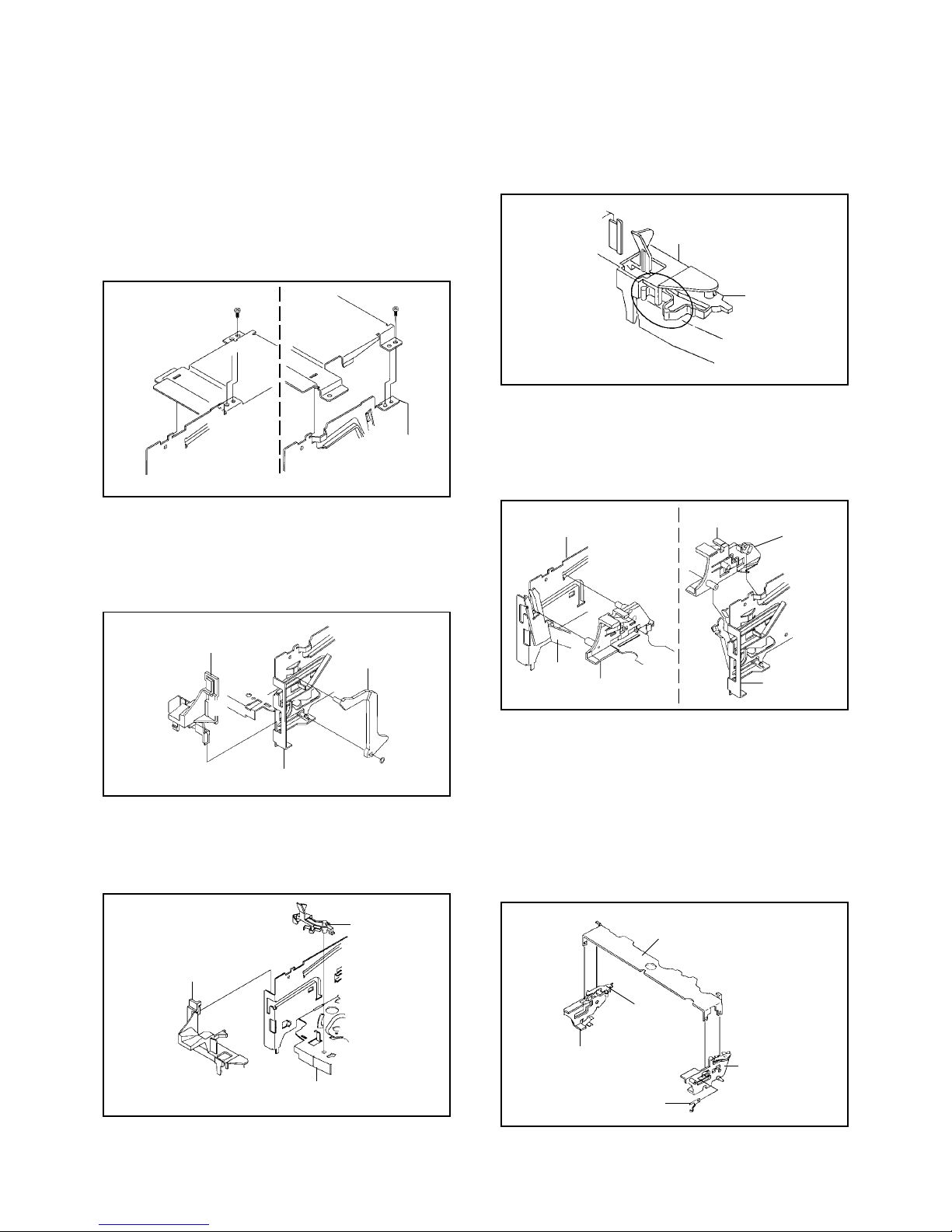
1-6: DECK CHASSIS (Refer to Fig. 1-6)
1.
2.
3.
Remove the 3 screws 1.
Disconnect the following connectors:
(CP1004, CP1005, CP1006, CP4001, CP4004 and
CP4005).
Remove the Deck Chassis in the direction of arrow.
1-5: DECK SHIELD PLATE (Refer to Fig. 1-5)
1.
2.
3.
4.
5.
6.
Remove the 2 screws 1.
Remove the 4 screws 2.
Remove the screw 3.
Remove the Deck Shield Plate in the direction of arrow (A).
Remove the screw 4.
Remove the Shield Plate Bottom in the direction of arrow (B).
Syscon PCB
(A)
Deck Holder Fig. 1-7
3
3
(B)
2
2
Jack Plate
1
1.
2.
3.
4.
5.
Remove the screw 1.
Remove the Syscon PCB in the direction of arrow (A).
Remove the 2 screws 2.
Unlock the 2 supports 3.
Remove the Jack Plate in the direction of arrow (B).
1-7: JACK PLATE AND SYSCON PCB (Refer to Fig. 1-7)
11
1
Fig. 1-6
B1-2
Deck Chassis
Syscon PCB
Shield Plate Bottom
VCR Block
3
1
Deck Shield Plate
DISASSEMBLY INSTRUCTIONS
2. REMOVAL OF DECK PARTS
2-1: TOP BRACKET (Refer to Fig. 2-1)
Remove the 2 screws 1.
Slide the 2 supports 2and remove the Top Bracket.
1.
2.
NOTE
When you install the Top Bracket, install the screw (1)
first, then install the screw (2).
1
(2)
Top Bracket Top Bracket
Main Chassis
Main Chassis
2
1
(1)
2
Fig. 2-1
NOTE
When you install the Tape Guide L, install as shown in the
circle of Fig. 2-3-B. (Refer to Fig. 2-3-B)
REC Lever
Tape Guide L
• The REC Lever is not installed on the Video Cassette Player. Fig. 2-3-B
• Screw Torque: 5 ±0.5kgf•cm
B2-1
2-2: FLAP LEVER/TAPE GUIDE R (Refer to Fig. 2-2)
Move the Cassette Holder Ass'y to the back side.
Remove the Polyslider Washer 1.
Remove the Flap Lever.
Unlock the 3 supports 2and remove the Tape Guide R.
1.
2.
3.
4.
Fig. 2-2
2-3: TAPE GUIDE L (Refer to Fig. 2-3-A)
Move the Cassette Holder Ass'y to the back side.
Unlock the 2 supports 1and remove the Tape Guide L.
Remove the REC Lever. (Recorder only)
1.
2.
3.
1
Main Chassis
Tape Guide L
REC Lever
Fig. 2-3-A
• The REC Lever is not installed on the Video Cassette Player.
1
1
2
2
2
Tape Guide R
Flap Lever
Main Chassis
2-4: CASSETTE HOLDER ASS'Y (Refer to Fig. 2-4)
Move the Cassette Holder Ass'y to the front side so that
the Link Ass'y doesn't slip out.
Push the Locker R to remove the Cassette Side R.
Remove the Cassette Side L.
1.
2.
3.
Main Chassis
Main Chassis
Cassette Side L
Cassette Side R Locker R
Fig. 2-4
2-5: CASSETTE SIDE L/R (Refer to Fig. 2-5)
Link Ass'y
Unlock the 4 supports 1and then remove the Cassette
Side L/R.
Remove the Cassette Earth Spring.
1.
2.
NOTE
1.
2.
When you install the Cassette Side R, be sure to move
the Locker R after installing.
After the installation of the Cassette Holder, then install
the Cassette Earth Spring.
Cassette Side L
Cassette Side R
1
1
1
Locker R 1
Cassette Holder
Fig. 2-5
Cassette Earth Spring

DISASSEMBLY INSTRUCTIONS
2-6: LINK ASS'Y (Refer to Fig. 2-6)
Set the Link Ass'y to the Eject position.
Remove the (A) side of the Link Ass'y first, then remove
the (B) side.
1.
2.
Main Chassis
(A)
Main Chassis
Link Ass'y
Fig. 2-6
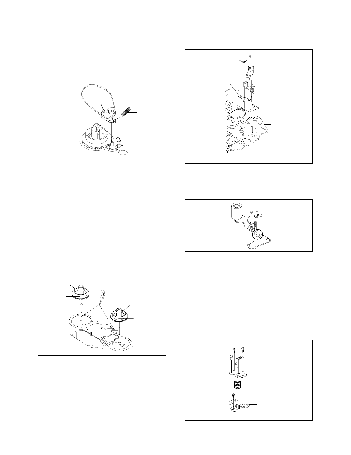
2-7: LOADING MOTOR ASS'Y (Refer to Fig. 2-7)
Remove the Link Lever.
Remove the Dumper Spring.
Remove the 2 screws 1.
Unlock the support 2and remove the Loading Motor
Ass'y.
Unlock the 2 supports 3and remove the Deck PCB
(BOT).
1.
2.
3.
4.
5.
1
2
1
Loading Motor Ass'y
Link Lever
Main Chassis
• Screw Torque: 5 ±0.5kgf•cm Fig. 2-7
2-8: SENSOR COVER L3 (Refer to Fig. 2-8)
Unlock the support 1and remove the Sensor Cover L3.1.
Deck PCB
(BOT)
Link Ass'y
(B)
Dumper Spring
3
B2-2
Main Chassis
Sensor Cover L3
1
Fig. 2-8
2-9: TENSION ASS'Y (Refer to Fig. 2-9-B)
Turn the Middle Gear clockwise so that the Tension
Holder hook, is set to the position of Fig. 2-9-A to more
the Tension Arm Ass'y.
Remove the Tension Spring.
Unlock the support 1and remove the Tension Arm
Ass'y.
Remove the Tension Adjust.
Unlock the 2 supports 2and remove the Tension Band
Ass'y.
Float the hook 3and turn it clockwise then remove the
Tension Holder.
Remove the SS Brake Spring.
Remove the SS Arm Brake.
1.
2.
3.
4.
5.
6.
7.
8.
Fig. 2-9-A
Tension Arm Ass'y
3
1
2
2
Tension Adjust
Tension Band Ass'y
Tension Spring Tension Arm Ass'y
Tension Holder
Inclined S Ass'y
Fig. 2-9-B
SS Brake Spring
SS Arm Brake
NOTE
When you install the Tension Adjust, install as shown in
Fig. 2-9-C. (Refer to Fig. 2-9-C)
Fig. 2-9-C
Adjust the direction of the Marker to inside.
DISASSEMBLY INSTRUCTIONS
B2-3
T Brake Spring
Hook section
2-10: T BRAKE ASS'Y (Refer to Fig. 2-10)
Remove the T Brake Spring.
Turn the T Brake Ass'y clockwise and bend the hook
section to remove it.
1.
2.
T Brake Ass'y
Fig. 2-10
2-11: S REEL/T REEL (Refer to Fig. 2-11)
Remove the S Reel and T Reel.
Remove the 2 Polyslider Washers 1.
1.
2.
NOTE
Take care not to damage the gears of the S Reel and T
Reel.
The Polyslider Washer may be remained on the back of
the reel.
Take care not to damage the shaft.
Do not touch the section "A" of S Reel and T Reel. (Use
gloves.) (Refer to Fig. 2-11) Do not adhere the stains
on it.
When you install the reel, clean the shaft and oil it (FL
OIL #6115). (If you do not oil, noise may be heard in FF/
REW mode.)
After installing the reel, adjust the height of the reel.
(Refer to MECHANICAL ADJUSTMENT)
1.
2.
3.
4.
5.
6.
S Reel
1
(A)
T Reel
(A)
1
Fig. 2-11
2-12: PINCH ROLLER BLOCK/P5-3 ARM ASS'Y
(Refer to Fig. 2-12-A)
Remove the P5 Spring.
Remove the screw 1.
Unlock the 2 supports 2and remove the Cassette
Opener.
Remove the Pinch Roller Block, Pinch Roller Arm
Spring, Pinch Roller Lever Ass'y and P5-3 Arm Ass'y.
1.
2.
3.
4.
1
2
2
P5 Spring
Cassette Opener
P5-3 Arm Ass'y
Pinch Roller Block
Pinch Roller Lever Ass'y
Main Chassis
Fig. 2-12-A
Pinch Roller Arm Spring
• Screw Torque: 5 ±0.5kgf•cm
NOTE
Do not touch the Pinch Roller. (Use gloves.)
When you install the Pinch Roller Block, install as shown
in the circle of Fig. 2-12-B. (Refer to Fig. 2-12-B)
1.
2.
Fig. 2-12-B
2-13: A/C HEAD (Refer to Fig. 2-13-A)
Remove the screw 1.
Remove the A/C Head Base.
Remove the 3 screws 2.
Remove the A/C Head and A/C Head Spring.
1.
2.
3.
4.
NOTE
Do not touch the A/C Head. (Use gloves.)
When you install the A/C Head Spring, install as shown
in Fig. 2-13-B. (Refer to Fig. 2-13-B)
When you install the A/C Head, tighten the screw (1)
first, then tighten the screw (2), finally tighten the screw
(3).
1.
2.
3.
A/C Head
2
2
A/C Head Spring
1
(3)
(1)
2
(2)
A/C Head Base
Fig. 2-13-A
• Screw Torque: 4 ±0.5kgf•cm (Screw 1)

DISASSEMBLY INSTRUCTIONS
B2-4
Spring Position Fig. 2-13-B
2-14: FE HEAD (RECORDER ONLY) (Refer to Fig. 2-14)
Remove the screw 1.
Remove the FE Head.
1.
2.
1
FE Head
• The FE Head is not installed on the Video Cassette Player.
• Screw Torque: 4 ±0.5kgf•cm Fig. 2-14
2-15: AHC ASS'Y/CYLINDER UNIT ASS'Y
(Refer to Fig. 2-15)
Unlock the support 1and remove the AHC Ass'y.
Remove the 3 screws 2.
Remove the Cylinder Unit Ass'y.
1.
2.
3.
When you install the Cylinder Unit Ass'y, tighten the
screws from (1) to (3) in order while pulling the Ass'y
toward the left front direction.
NOTE
1
AHC Ass'y
Cylinder Unit Ass'y
2
2
2
• Screw Torque: 3 ±0.5kgf•cm Fig. 2-15
(1)
(3)
(2)
• Screw Torque: 5 ±0.5kgf•cm Fig. 2-16
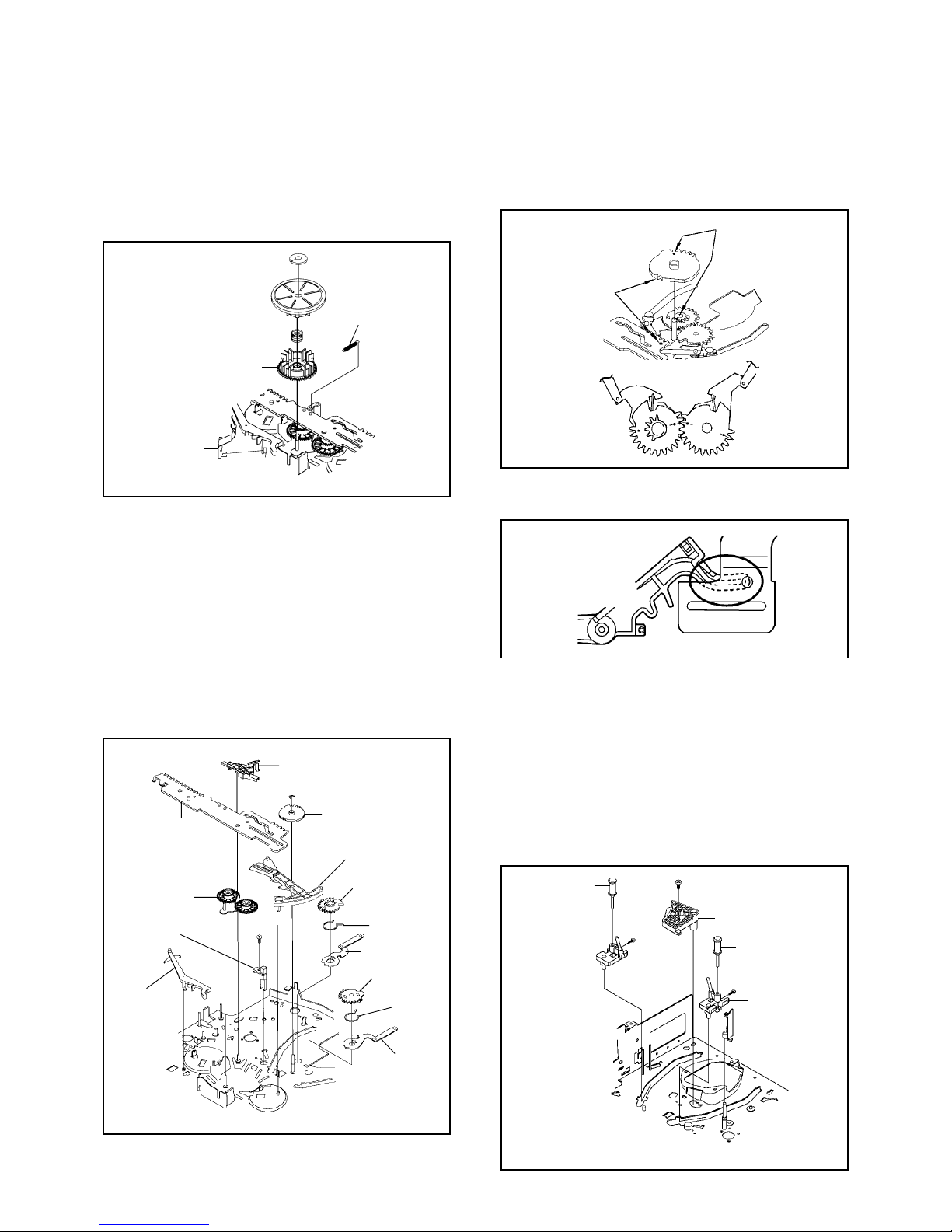
2-17: MIDDLE GEAR/MAIN CAM (Refer to Fig. 2-17-A)
Remove the Polyslider Washer 1, then remove the
Middle Gear.
Remove the E-Ring, then remove the Main Cam, P5
Cam and Pinch Roller Cam.
Remove the Polyslider Washer 2, then remove the
Joint Gear.
1.
2.
3.
Capstan DD Unit
Capstan Belt
11
1
2-16: CAPSTAN DD UNIT (Refer to Fig. 2-16)
Remove the Capstan Belt.
Remove the 3 screws 1.
Remove the Capstan DD Unit.
1.
2.
3.
1
2
E-Ring
Middle Gear
Main Cam
Pinch Roller Cam
Joint Gear
P5 Cam
Fig. 2-17-A
NOTE
When you install the Pinch Roller Cam, P5 Cam and Main
Cam, align each marker. (Refer to Fig. 2-17-B)
Pinch Roller Cam
P5 Cam
Main Cam
Marker
Check the hole of Main
Chassis can be seen.
Fig. 2-17-B
DISASSEMBLY INSTRUCTIONS
B2-5
2-18: CLUTCH ASS'Y (Refer to Fig. 2-18)
Remove the Capstan Brake Spring.
Remove the Polyslider Washer 1.
Remove the Clutch Ass'y, Ring Spring and Coupling
Gear.
Unlock the 2 supports 2and remove the Clutch Lever.
1.
2.
3.
4.
Fig. 2-18
1
Clutch Ass'y
Coupling Gear
Clutch Lever
Ring Spring
2
2
Capstan Brake Spring
2-19: LOADING GEAR S/T ASS'Y (Refer to Fig. 2-19-A)
1.
2.
3.
4.
5.
6.
7.
8.
Remove the E-Ring 1and remove the Main Loading
Gear.
Slide the Main Rod and remove the Capstan Brake
Ass'y.
Remove the Main Rod, Tension Lever, Clutch Actuator,
Idler Arm Ass'y.
Remove the screw 2.
Remove the LED Reflecter.
Remove the Loading Arm S Ass'y and Loading Arm T
Ass'y.
Remove the Loading Gear S and Loading Gear T.
Remove the Loading Gear Spring.
1
2
Capstan Brake Ass'y
Main Rod Main Loading Gear
Tension Lever
Loading Gear T
Loading Gear
Spring
Loading Arm T Ass'y
Loading Gear S
Loading Gear
Spring
Loading Arm S Ass'y
LED Reflecter
Idler Arm Ass'y
Clutch Actuator
• Screw Torque: 5 ±0.5kgf•cm Fig. 2-19-A
NOTES
1. When you install the Loading Arm S Ass'y, Loading Arm
T Ass'y and Main Loading Gear, align each marker.
(Refer to Fig. 2-19-B)
Marker
Main Loading Gear
Marker
Loading Arm T Ass'y Loading Arm S Ass'y
Fig. 2-19-B
2. When you install the Clutch Actuator, install as shown in
the circle of Fig. 2-19-C. (Refer to Fig. 2-19-C)
Clutch Actuator
Fig. 2-19-C
NOTE
Do not touch the roller of Guide Roller.
2-20: INCLINED S/T ASS'Y (Refer to Fig. 2-20)
Unlock the support 1and remove the P4 Cover.
Remove the screw 2.
Unlock the support 3and remove the Loading Gear
Holder.
Remove the Inclined S.
Remove the Inclined T.
Remove the 2 screws 4, then remove the Guide Roller.
1.
2.
3.
4.
5.
6.
Inclined T
P4 Cover
Guide Roller
Inclined S
1
4
4
Guide Roller
Loading Gear Holder
2
3
• Screw Torque: 5 ±0.2kgf•cm (Screw 2)
• Screw Torque: 0.7 ±0.2kgf•cm (Screw 4)Fig. 2-20
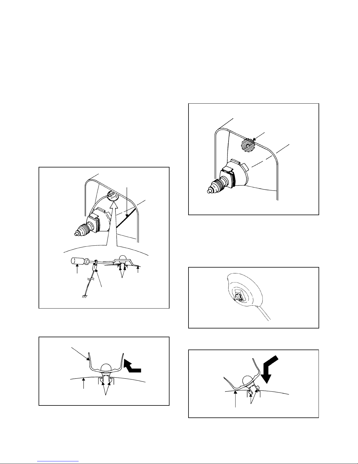
3. REMOVAL OF ANODE CAP
Read the following NOTED items before starting work.
After turning the power off there might still be a potential
voltage that is very dangerous. When removing the
Anode Cap, make sure to discharge the Anode Cap's
potential voltage.
Do not use pliers to loosen or tighten the Anode Cap
terminal, this may cause the spring to be damaged.
REMOVAL
1. Follow the steps as follows to discharge the Anode Cap.
(Refer to Fig. 3-1.)
Connect one end of an Alligator Clip to the metal part of a
flat-blade screwdriver and the other end to ground.
While holding the plastic part of the insulated Screwdriver,
touch the support of the Anode with the tip of the
Screwdriver.
A cracking noise will be heard as the voltage is discharged.
Flip up the sides of the Rubber Cap in the direction of the
arrow and remove one side of the support.
(Refer to Fig. 3-2.)
2.
DISASSEMBLY INSTRUCTIONS
GND on the CRT
Screwdriver
Alligator Clip
Support CRT
GND on the CRT
Rubber Cap
CRT Support
Fig. 3-1
Fig. 3-2
3. After one side is removed, pull in the opposite direction to
remove the other.
NOTE
Take care not to damage the Rubber Cap.
INSTALLATION
1. Clean the spot where the cap was located with a small
amount of alcohol. (Refer to Fig. 3-3.)
NOTE
Confirm that there is no dirt, dust, etc. at the spot where
the cap was located.
2.
3.
Arrange the wire of the Anode Cap and make sure the
wire is not twisted.
Turn over the Rubber Cap. (Refer to Fig. 3-4.)
Location of Anode Cap
Fig. 3-3
Fig. 3-4
B3-1
*
*
4. Insert one end of the Anode Support into the anode button,
then the other as shown in Fig. 3-5.
5.
6. Confirm that the Support is securely connected.
Put on the Rubber Cap without moving any parts.
CRT Support Fig. 3-5

B4-1
Masking Tape
(Cotton Tape)
DISASSEMBLY INSTRUCTIONS
4.
REMOVAL
IC
Put the Masking Tape (cotton tape) around the Flat
Package IC to protect other parts from any damage.
(Refer to Fig. 4-1.)
1.
Fig. 4-1
NOTE
REMOVAL AND INSTALLATION OF
FLAT PACKAGE IC
Some ICs on the PCB are affixed with glue, so be
careful not to break or damage the foil of each IC
leads or solder lands under the IC when removing it.
NOTE
Masking is carried out on all the parts located within
10 mm distance from IC leads.
Blower type IC
desoldering machine
IC
Heat the IC leads using a blower type IC desoldering
machine. (Refer to Fig. 4-2.)
2.
Fig. 4-2
NOTE
Do not add the rotating and the back and forth
directions force on the IC, until IC can move back and
forth easily after desoldering the IC leads completely.
When IC starts moving back and forth easily after
desoldering completely, pickup the corner of the IC using
a tweezers and remove the IC by moving with the IC
desoldering machine. (Refer to Fig. 4-3.)
3.
Blower type IC
desoldering
machine
IC Fig. 4-3
Tweezers
Peel off the Masking Tape.4.
Absorb the solder left on the pattern using the Braided
Shield Wire. (Refer to Fig. 4-4.)
5.
NOTE
Do not move the Braided Shield Wire in the vertical
direction towards the IC pattern.
Braided Shield Wire
Soldering Iron
Fig. 4-4
IC pattern

B4-2
DISASSEMBLY INSTRUCTIONS
Supply soldering
from upper position
to lower position
IC
Supply the solder from the upper position of IC leads
sliding to the lower position of the IC leads.
(Refer to Fig. 4-6.)
2.
Fig. 4-6
Soldering IronSolder
IC
Absorb the solder left on the lead using the Braided
Shield Wire. (Refer to Fig. 4-7.)
3.
Fig. 4-7
Soldering Iron
Braided Shield Wire
NOTE
Do not absorb the solder to excess.
IC
When bridge-soldering between terminals and/or the
soldering amount are not enough, resolder using a Thin-
tip Soldering Iron. (Refer to Fig. 4-8.)
4.
Fig. 4-8
Thin-tip Soldering Iron
NOTE
When the IC leads are bent during soldering and/or
repairing, do not repair the bending of leads. If the
bending of leads are repaired, the pattern may be
damaged. So, be always sure to replace the IC in this
case.
Finally, confirm the soldering status on four sides of the
IC using a magnifying glass.
Confirm that no abnormality is found on the soldering
position and installation position of the parts around the
IC. If some abnormality is found, correct by resoldering.
5.
Solder temporarily
Soldering Iron
INSTALLATION
Take care of the polarity of new IC and then install the
new IC fitting on the printed circuit pattern. Then solder
each lead on the diagonal positions of IC temporarily.
(Refer to Fig. 4-5.)
1.
Fig. 4-5
Solder temporarily

KEY TO ABBREVIATIONS
A
B
C
D
E
F
G
H
A/C
ACC
AE
AFC
AFT
AFT DET
AGC
AMP
ANT
A.PB
APC
ASS'Y
AT
AUTO
A/V
BGP
BOT
BPF
BRAKE SOL
BUFF
B/W
C
CASE
CAP
CARR
CH
CLK
CLOCK (SY-SE)
COMB
CONV
CPM
CTL
CYL
CYL-M
CYL SENS
DATA (SY-CE)
dB
DC
DD Unit
DEMOD
DET
DEV
E
EF
EMPH
ENC
ENV
EOT
EQ
EXT
F
FBC
FE
FF
FG
FL SW
FM
FSC
FWD
GEN
GND
H.P.F
:
:
:
:
:
:
:
:
:
:
:
:
:
:
:
:
:
:
:
:
:
:
:
:
:
:
:
:
:
:
:
:
:
:
:
:
:
:
:
:
:
:
:
:
:
:
:
:
:
:
:
:
:
:
:
:
:
:
:
:
:
:
Audio/Control
Automatic Color Control
Audio Erase
Automatic Frequency Control
Automatic Fine Tuning
Automatic Fine Tuning Detect
Automatic Gain Control
Amplifier
Antenna
Audio Playback
Automatic Phase Control
Assembly
All Time
Automatic
Audio/Video
Burst Gate Pulse
Beginning of Tape
Bandpass Filter
Brake Solenoid
Buffer
Black and White
Capacitance, Collector
Cassette
Capstan
Carrier
Channel
Clock
Clock (Syscon to Servo)
Combination, Comb Filter
Converter
Capstan Motor
Control
Cylinder
Cylinder-Motor
Cylinder-Sensor
Data (Syscon to Servo)
Decibel
Direct Current
Direct Drive Motor Unit
Demodulator
Detector
Deviation
Emitter
Emitter Follower
Emphasis
Encoder
Envelope
End of Tape
Equalizer
External
Fuse
Feed Back Clamp
Full Erase
Fast Forward, Flipflop
Frequency Generator
Front Loading Switch
Frequency Modulation
Frequency Sub Carrier
Forward
Generator
Ground
High Pass Filter
I
K
L
M
N
O
P
R
S
H.SW
Hz
IC
IF
IND
INV
KIL
L
LED
LIMIT AMP
LM, LDM
LP
L.P.F
LUMI.
M
MAX
MINI
MIX
MM
MOD
MPX
MS SW
NC
NR
OSC
OPE
PB
PB CTL
PB-C
PB-Y
PCB
P. CON
PD
PG
P-P
R
REC
REC-C
REC-Y
REEL BRK
REEL S
REF
REG
REW
REV, RVS
RF
RMC
RY
S. CLK
S. COM
S. DATA
SEG
SEL
SENS
SER
SI
SIF
SO
SOL
SP
STB
SW
:
:
:
:
:
:
:
:
:
:
:
:
:
:
:
:
:
:
:
:
:
:
:
:
:
:
:
:
:
:
:
:
:
:
:
:
:
:
:
:
:
:
:
:
:
:
:
:
:
:
:
:
:
:
:
:
:
:
:
:
:
:
Head Switch
Hertz
Integrated Circuit
Intermediate Frequency
Indicator
Inverter
Killer
Left
Light Emitting Diode
Limiter Amplifier
Loading Motor
Long Play
Low Pass Filter
Luminance
Motor
Maximum
Minimum
Mixer, mixing
Monostable Multivibrator
Modulator, Modulation
Multiplexer, Multiplex
Mecha State Switch
Non Connection
Noise Reduction
Oscillator
Operation
Playback
Playback Control
Playback-Chrominance
Playback-Luminance
Printed Circuit Board
Power Control
Phase Detector
Pulse Generator
Peak-to Peak
Right
Recording
Recording-Chrominance
Recording-Luminance
Reel Brake
Reel Sensor
Reference
Regulated, Regulator
Rewind
Reverse
Radio Frequency
Remote Control
Relay
Serial Clock
Sensor Common
Serial Data
Segment
Select, Selector
Sensor
Search Mode
Serial Input
Sound Intermediate Frequency
Serial Output
Solenoid
Standard Play
Serial Strobe
Switch
C1-1

KEY TO ABBREVIATIONS
S
T
U
V
X
Y
SYNC
SYNC SEP
TR
TRAC
TRICK PB
TP
UNREG
V
VCO
VIF
VP
V.PB
VR
V.REC
VSF
VSR
VSS
V-SYNC
VT
X'TAL
Y/C
:
:
:
:
:
:
:
:
:
:
:
:
:
:
:
:
:
:
:
:
:
Synchronization
Sync Separator, Separation
Transistor
Tracking
Trick Playback
Test Point
Unregulated
Volt
Voltage Controlled Oscillator
Video Intermediate Frequency
Vertical Pulse, Voltage Display
Video Playback
Variable Resistor
Video Recording
Visual Search Fast Forward
Visual Search Rewind
Voltage Super Source
Vertical-Synchronization
Voltage Tuning
Crystal
Luminance/Chrominance
C1-2
C2-1
SERVICE MODE LIST
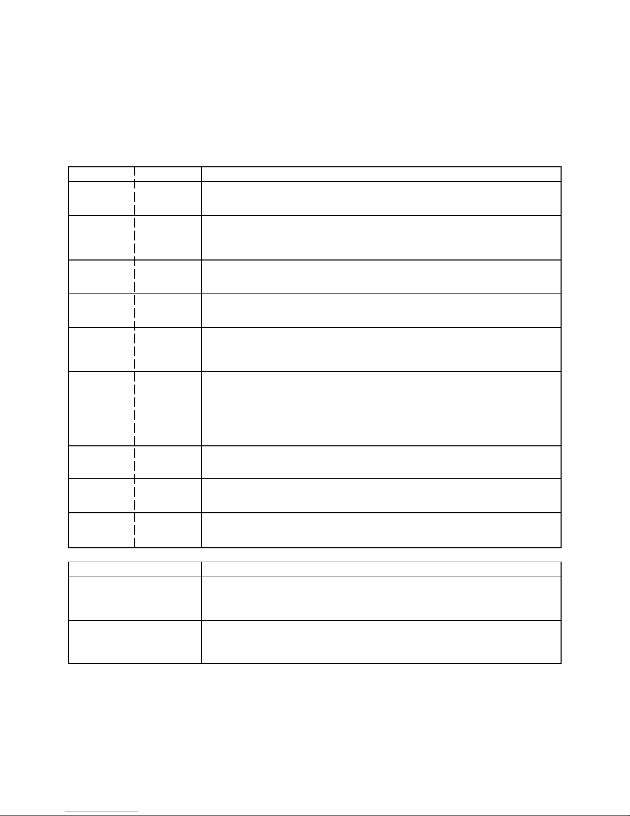
This unit provided with the following SERVICE MODES so you can repair, examine and adjust easily.
To enter SERVICE MODE, unplug AC cord till lost actual clock time. Then press and hold Vol (-) button of main unit and
remocon key for more than 2 seconds.
The both pressing of set key and remote control key will not be possible if clock has been set. To reset clock, either unplug
AC cord and allow at least 30 minutes before Power On or alternatively, discharge backup capacitor.
Set Key Remocon Key Operations
VOL. (-) MIN 1 Initialization of the factory.
NOTE: Do not use this for the normal servicing.
VOL. (-) MIN 3Adjust the PG SHIFTER automatically.
Refer to the "ELECTRICAL ADJUSTMENT" (PG SHIFTER).
VOL. (-) MIN 4 Adjust the PG SHIFTER manually.
Refer to the "ELECTRICAL ADJUSTMENT" (PG SHIFTER).
VOL. (-) MIN 5
VOL. (-) MIN 2 Horizontal position adjustment of OSD.
NOTE: Also can be adjusted by using the Adjustment MENU.
Refer to the "ELECTRICAL ADJUSTMENT" (OSD HORIZONTAL).
POWER ON total hours and PLAY/REC total hours are displayed on the screen.
Refer to the "PREVENTIVE CHECKS AND SERVICE INTERVALS" (CONFIRMATION
OF HOURS USED).
Can be checked of the INITIAL DATA of MEMORY IC.
Refer to the "WHEN REPLACING EEPROM (MEMORY) IC".
VOL. (-) MIN 6
VOL. (-) MIN 9 Display of the Adjustment MENU on the screen.
Refer to the "ELECTRICAL ADJUSTMENT" (On-Screen Display Adjustment).
VOL. (-) MIN 8 Writing of EEPROM initial data.
NOTE: Do not use this for the normal servicing.
VOL. (-) MIN 7 Releasing of PROTECTION PASSWORD.
Adjusting of the Tracking to the center position.
NOTE: Also can be adjusted by pressing the ATR button for more tan 2 seconds
during PLAY.
Method Operations
Adjusting of the Tracking to the center position.
Refer to the "MECHANICAL ADJUSTMENT" (GUIDE ROLLER) and "ELECTRICAL
ADJUSTMENT" (PG SHIFTER).
Press the ATR button on the
remote control for more than
2 seconds during PLAY.
Make the short circuit between
the test point of SERVICE and
the GND.
The EOT/BOT/Reel sensor do not work at this moment.
Refer to the "PREPARATION FOR SERVICING"
Table of contents
Other Schaub Lorenz TV VCR Combo manuals


