Schaudt CSV 416 User manual

30.05.2021
ESchaudt GmbH, Elektrotechnik und Apparatebau, Planckstraße 8, 88677 Markdorf, Germany, Tel. +49 7544 9577-0, Fax +49 7544 9577-29, www.schaudt--gmbh.de
8050111 BA
Operating Instructions
Caravan-charging system CSV 416
Table of contents
1 Introduction 2............................................
2 Safety information 2......................................
2.1 Meaning of safety symbols 2...............................
2.2 General safety information 2...............................
3 Operation 3..............................................
3.1 Starting up caravan charging system 4......................
3.2 Switching on and off 5.....................................
3.3 Changing the battery 5....................................
4 Application and function 7.................................
4.1 Battery functions 8........................................
4.2 Additional functions 10.....................................
5 Layout 11................................................
5.1 Operating faults 12........................................
5.2 Switching off the system 13.................................
5.3 Closing down the system 13................................
6 Technical details 14........................................
6.1 Mechanical details 14......................................
6.2 Electrical details 14........................................
6.3 Environmental parameters 15...............................
7 Maintenance 15...........................................
Appendix 16..............................................

Operating Instructions Caravan-charging system CSV 416
2Date: 30.05.2021 8050111 BA / EN
1 Introduction
This instruction manual contains important information for the safe operation
of equipment supplied by Schaudt. Make sure you read and follow the safety
instructions provided.
The operating instructions should always be kept in the vehicle. All safety
information must be passed on to other users.
2 Safety information
2.1 Meaning of safety symbols
YDANGER!
Failure to comply with this sign may result in danger to life or physical
condition.
YWARNING!
Failure to comply with this sign may result in injury.
YATTENTION!
Failure to comply with the sign may result in damage to equipment or other
connected consumers.
YThis symbol references recommendations or special features.
2.2 General safety instructions
The design of the device is state-of-the-art and complies with approved
safety regulations. Failure to observe the safety instructions may nonethe-
less lead to injury or damage to the device.
Only use the device when it is in perfect technical condition.
Any faults affecting the safety of individuals or the proper functioning of the
device must be repaired immediately by specialists.
YDANGER!
230V units carrying mains voltage.
Risk of fatal injury due to electric shock or fire:
FThe motorhome or caravan’s electrical system must comply with DIN,
VDE and ISO regulations.
FNever try to modify the electrical system.
FDo not try to modify the device.
FOnly qualified electricians are permitted to establish electrical connec-
tions in accordance with the installation instructions supplied by
Schaudt.
FConnection work may only be carried out after the power has been
disconnected.
Operating Instructions Caravan-charging system CSV 416
3
Date: 30.05.2021
8050111 BA / EN
FNever try to start the device using a defective mains cable or a faulty
connection.
FNever undertake maintenance on the device when it is live.
YDANGER!
Incorrect installation
Electric shock or damage to connected devices:
FInstall as shown in installation instructions.
FThe mains connection line may only be replaced by an authorised
customer service department or by those qualified.
YWARNING!
Hot components
Burns:
FBlown fuses may only be changed after the power to the system has
been disconnected
FBlown fuses may only be replaced once the cause of the fault is
known and has been rectified
FNever bypass or repair fuses
FThe back of the device can get hot during operation. Do not touch
them.
FOnly use original fuses rated as specified on the device
FNever store heat sensitive objects close to the device (e.g. tempera-
ture sensitive clothes if the device has been installed in a wardrobe)
3 Operation
YThis device is not intended to be used by those (including children) with
limited physical, sensory or mental aptitude or lack of experience and/or
knowledge unless they are supervised by a person responsible for their
safety or have received instruction from this person as to how the device
is used.
Children must be supervised to ensure they do not play with the device.
This device is intended for installation into a vehicle.
YThe caravan charging system is operated solely from the control and
switch panel connected.
The CSV 416A caravan charging system does not require daily operation.
Initial setting is only needed after the type of battery (lead-acid / lead-gel) is
changed, or for initial use or when upgrading with accessories (see section
3.3 and the CSV 416A installation instructions for details).

Operating Instructions Caravan-charging system CSV 416
4Date: 30.05.2021 8050111 BA / EN
3.1 Starting up the caravan charging system
YATTENTION!
An incorrect setting on the caravan charging system will result in damage to
the battery connected. Ensure therefore that, prior to start-up, the battery
selector switch (Fig. 4, Pos. 10) is in the correct position for the battery
installed.
YATTENTION!
The caravan charging system, 12V consumers and connected devices can
be damaged if the thresholds for the 230V supply are exceeded. So there-
fore:
FDo not connect a generator until it is running smoothly.
FIt is essential that the generator conforms to the specifications of the
mains supply.
FDo not connect the caravan charging system to the onboard mains
voltage on car ferries (non-problematic mains voltage cannot always
be guaranteed on car ferries).
The use of an upstream overvoltage protection device is recommen-
ded.
YATTENTION!
When connecting a solar regulator, note that the buffer function of the bat-
tery is an absolute requirement, i.e. the battery must be connected before a
solar regulator is connected.
YATTENTION!
Switch off the ignition when the towing vehicle is parked (when the caravan
is connected to the towing vehicle). Otherwise the starter battery of the
towing vehicle might discharge.
Battery
Generator operation and
passenger vehicle
ferries
Operation with solar
regulator
Operation on towing
vehicle
Operating Instructions Caravan-charging system CSV 416
5
Date: 30.05.2021
8050111 BA / EN
3.2 Switching on and off
Control and switch panels must be supplied with a separate operating ma-
nual (kept with the vehicle). Please refer to this manual for instructions on
operation.
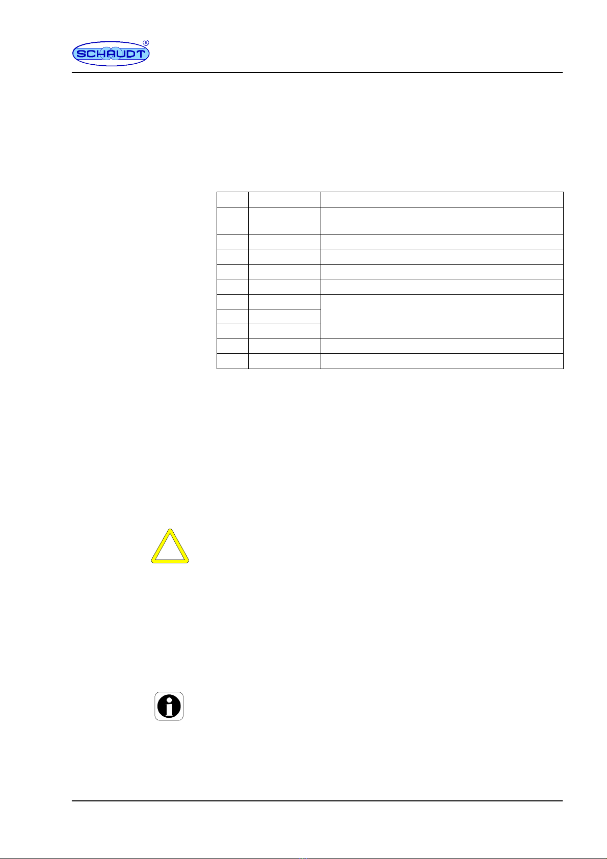
Activating the 12V main switch (12V ON) on the operating panel connected
enables/disables the following electrical circuits:
Pos. Circuit Fuse with
1Heater 10 A -- With the mains supply, there is no switch-off
by the main 12V switch
2 Pump/WC 10 A -- Can be enabled individually over the bus
3Circuit 1 15 A -- Can be enabled individually over the bus
4Circuit 2 15 A -- Can be enabled individually over the bus
5Circuit 3 15 A
6Awning light
10 A7TV
8Spare
5Circuit 4 15 A
5Circuit 5 10 A
Outputs
Fswitching output 1
Fswitching output 2
Fswitching output N
can only be enabled over the bus, regardless of whether the main 12V
switch (12V ON) is switched on or off.
3.3 Changing the battery
YATTENTION!
The use of incorrect battery types or incorrectly designed batteries can
damage the battery itself or devices connected to the caravan charging
system. So therefore:
FBatteries may only be changed by qualified personnel.
FFollow the battery manufacturer’s instructions.
FThe caravan charging system is only suited for connecting to 12V
power supplies with chargeable batteries (of the types specified be-
low).
FDo not use non-approved battery types such as NiMH batteries.
YNormally only batteries of the same type and capacity should be used,
i.e. the same as those installed by the manufacturer.
It is possible to swap from lead-acid batteries to other battery types.
Switching to lead-acid batteries is only possible in certain circumstances.
Contact the vehicle manufacturer for more information.

Operating Instructions Caravan-charging system CSV 416
6Date: 30.05.2021 8050111 BA / EN
Proceed as follows for a battery change:
"Disconnect the battery from the caravan charging system by switching
themain12Vswitchoff.
"Disconnect the caravan charging system from the 230 V supply.
"Unhitch the caravan from the towing vehicle.
"Replace the battery.
"After changing the battery, recheck which type of battery has been inser-
ted.
YDANGER!
Incorrectly setting the battery selector switch poses a risk of explosion (by
the formation of detonating gas). Move the battery selector switch to the
correct position
1 2
Fig. 1 Battery selector switch
"Move both battery selector switches (Fig. 1, Pos. 1) to the correct posi-
tion using a thin object (e.g. a ballpoint pen):
Battery type Switch 2/1 Switch B/A
Lead-acid batteries 2 B
Lead-gel batteries / AGM 1 batteries 2 A
AGM 2 batteries 1 B
Lithium batteries 1 A
"Start up the system as described in Section 3.1.
Changing
the battery
Starting up

Operating Instructions Caravan-charging system CSV 416
7
Date: 30.05.2021
8050111 BA / EN
4 Application and function
CSV 416 A
+--
+--
Caravan charging system
230V AC
12V consumers Caravan battery
Starter battery
Lighting
Pump
Heater
etc.
LR ...
Solar regulator
(accessory)
Towing vehicle
Control and
operator panel
(bus--compatible)
Bus
Other
bus nodes Water
tank Waste water
tank
Sensors
Fig. 2 On-board power supply system
The CSV 416 caravan charging system is the central power supply unit for
all 12 V consumers connected to the caravan’s electrical system. It is usually
located in a cupboard or storage area and is accessible from the front in
order to change fuses.
The caravan charging system has been designed solely for connecting to a
12 V onboard supply.
Connected units can be supplied from the caravan battery or the towing
vehicle’s battery if a mains supply is not available.
Because the device provides a hum-free, stabilised output voltage, sensitive
consumers such as transistor lights and radios can be connected and powe-
red.
The CSV 416A caravan charging system comprises:
Fa charge module for charging all batteries connected
Fa main switch relay to switch certain consumers on and off
Fthe complete 12V distribution system
Ffuses for the 12V circuits
Fa battery booster
FLIN bus interface
FTank analysis
Modules

Operating Instructions Caravan-charging system CSV 416
8Date: 30.05.2021 8050111 BA / EN
A bus-compatible control panel must be connected for operation.
Connections provided for:
FBus devices
FTwo tank sensors
FSolar charge regulator (optional)
Flat vehicle fuses protect the various circuits.
FExcess temperature
FOverload
FShort circuit
230V AC 10%, 47 -- 63 Hz sinusoidal, protection class I
12V outputs may only be loaded up to a maximum of 90% of the rated
current of the associated fuse (see block diagram or nameplate).
All consumers together may not exceed the following load:
FMains operation: 28 A
FOperation with towing vehicle, ignition ON: 8 A
4.1 Battery functions
Lead-acid, lead-gel, AGM (1/2) or lithium batteries from 80 Ah
Charging the caravan battery whilst driving; increasing the supply voltage
coming from the towing vehicle via the battery booster
Maximum charging current 8 A
Caravan battery
Characteristic charging curve IUoU
Final charging voltage Dependent on
battery type (see Section 6)
Charging current 28 A
Voltage for trickle charge Dependent on
battery type (see Section 6)
The main 12V switch on the control panel connected isolates most 12V
consumers from the caravan battery (see also Page 5).
This prevents the caravan battery from being slowly discharged by standby
currents.
The batteries can continue to be charged by the caravan charging system,
the towing vehicle or the solar charge regulator (if available), even when the
main battery switch is OFF.
Actuation
Protective circuits
Mains
Current
Batteries
Battery charging when
vehicle is moving
Battery charging for
mains connector
12V main switch

Operating Instructions Caravan-charging system CSV 416
9
Date: 30.05.2021
8050111 BA / EN
1
2
3
4
5
6
789
10
11
12
13
9
10
11
13
Relay circuit ”+12V for ignition ON” (connector no.
10)
from terminal 15
Voltage when ignition ON
Fig. 3 Connector for towing vehicle power socket
YFor the ”Automatic shutoff” and ”Towing vehicle battery standby current”
functions to be guaranteed in line with the following specifications, both
the 13-pin connector of the caravan, and the socket of the towing vehicle,
must be assigned as per EN 1648-1 (see Fig. 3).
Consumers are switched off (with the exception of these with a continual
supply, see Page 5) when the caravan is hitched to the towing vehicle and
the ignition is switched on (power on terminal 10 of trailer hitch TH). Consu-
mers can be switched on again at any time (the automatic disconnector
does not prevent this).
No standby current when the towing vehicle ignition is OFF, plus power
consumption of control electronics of refrigerator (see documentation from
refrigerator manufacturer and other consumers with a continual supply, see
Page 5); measurement taken when all consumers in the caravan are swit-
ched off.
For systems in which the CSV 416 caravan power supply is used, another
device monitors the leisure area battery voltage (such as the panel connec-
ted to the LIN bus). When the voltage is too low, this device must send a
control signal to the CSV 416, that disconnects all consumers from the
battery (12 V OFF and switching outputs 1 to 3 OFF).
If this battery monitoring function of the external device fails, and the leisure
area battery voltage falls to below 10.6V for longer than a minute, 12V OFF
and switch-off of switching outputs 1 to 3 are performed automatically by the
CSV 416.
YThis monitoring function of the CSV 416 is regarded as an emergency
function when the rest of the system is operating erroneously.
An internal monitoring function ascertains whether a caravan battery is
connected. If yes, a charge process is performed as in Section 6.2. If no
caravan battery is connected, the device transitions to supply mode and a
constant voltage of 13.2V is applied at the outputs.
Automatic disconnector
Standb
y
current
towing vehicle battery
Batter
y
monitor
Monitoring of the
battery connection

Operating Instructions Caravan-charging system CSV 416
10 Date: 30.05.2021 8050111 BA / EN
YThe input circuits of connected devices are then subjected to a lower load
than with a higher voltage.
YATTENTION!
The CSV 416 can no longer detect a deeply discharged battery (battery is
high-impedance) and so transitions to supply mode. When the battery ”reco-
vers” (such as with charging when the vehicle is moving using a booster, or
with solar charging), it is detected automatically again by the CSV 416 and
charged.
YFor a fully charged battery, the CSV 416 also transitions to supply mode
in isolated cases. It is not until battery charging is required again that the
charge process starts (as in Section 6.2).
4.2 Additional functions
This output supplies the control electronics of a fridge:
FFrom the caravan battery
FFrom the towing vehicle’s battery when the ignition is switched on
FFrom the mains supply when it is connected up
YThe refrigerator only operates on 12 V when the caravan is hitched to the
towing vehicle and the ignition is switched on.
YATTENTION!
The caravan / towing vehicle battery can be damaged beyond repair by a
total discharge. So therefore:
FAvoid continuous 12V operation.
The refrigerator only operates on 12V when the caravan is hitched to
the towing vehicle and its ignition is ON.
The water pump is connected directly to the CSV 416A (Pump output). The
supply voltage to the pump is enabled from the Pump switch on the operator
and control panel. The pump is switched on when a control voltage of 12V is
applied to input ”Water Tap Signal” (via a switch in the water tap). The other
output, ”WC”, is connected in parallel.
Maximum permitted charge current 27 A, protected with 30 A
Three switching outputs (1, 2 and 3) can be enabled with control over the
bus.
Output D+ shows whether:
Fthe caravan is hitched to a towing vehicle and
Fthe ignition of the towing vehicle is on
This means the booster is active.
YSignal D+ does not show whether the engine of the towing vehicle is
running. So when the ignition is on, but the engine is not started,the
battery of the towing vehicle is under load and could discharge fully.
Refrigerator controller
Water pump
Battery charging with
solar charging regulator
Switching outputs
D+
Operating Instructions Caravan-charging system CSV 416
11
Date: 30.05.2021
8050111 BA / EN
An internal shunt monitors the charge current and makes available a data
telegram on the LIN bus. Refer to the instructions for the associated control
panel with bus connection for whether a display is possible (see also the
block diagram in Appendix E).
5 Layout
1
2
3
4
5
1578 9 10 111213
14 16 17 18 19 20
24
23
22
6
21
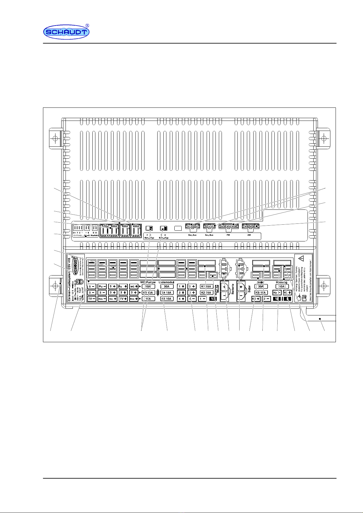
Fig. 4 Front view of CSV 416 A caravan charging system
1
2
3
4
5
6
7
8
9
10
11
12
Connector for water tap
Connector for refrigerator controller
Connectors for switching outputs 1, 2, 3 and D+
Adhesive label for functions (top)
Connectors for circuits 3 and 5, WC, pump, TV,
awning light and spare
Nameplate
Housing
Adhesive label for functions (front)
Battery selector switch 1/2 and A/B
Flat vehicle fuses, charger module
Circuits 3 to 5, spare
Connector for circuits 1, 2 and 4
Fuses for circuits 1 and 2
13
14
15
16
17
18
19
20
21
22
23
24
Connector for trailer coupling plug 10
Connector for caravan battery
Connector for solar charge regulator LR ...
Connector for refrigerator supply
Flat vehicle fuses, solar regulator and refrigera-
tor supply
Connector for heater
Connector for plug for trailer couplings 12 and 9
Flat vehicle fuse, heater
Mains cable
Connector for wastewater tank sensor
Connector for water tank sensor
LIN bus connectors
Monitoring of the
charge current (from
05/2021)

Operating Instructions Caravan-charging system CSV 416
12 Date: 30.05.2021 8050111 BA / EN
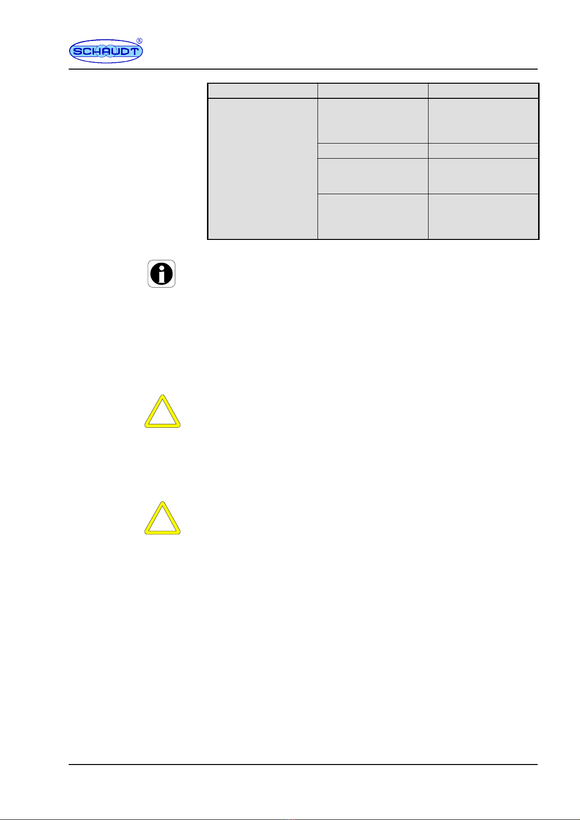
5.1 Faults
A fault in the power supply system is usually caused by a blown fuse.
Please contact our customer service address if you cannot rectify the fault
using the following table.
If this is not possible, e.g. if you are abroad, you can have the caravan
charging system repaired at a specialist workshop. In this case, you must
ensure that the warranty is not invalidated by incorrect repairs being carried
out. Schaudt GmbH will not accept any liability for damage resulting from
such repairs.
Fault Possible cause Remedy
Caravan battery is not
charged during 230 V
operation
No mains voltage Switch on the automatic
circuit breaker in the
vehicle; check the mains
voltage
Defective caravan char-
ging system
Contact customer service
Caravan battery is not
charged whilst driving
Defective alternator Have the alternator chec-
ked
No voltage applied to
”Ignition ON” input or
permanent plus
Have the fuse and cabling
checked
Check the towing vehicle
plug connection
Defective caravan char-
ging system
Contact customer service
Solar charger is not
working (mains supply off)
Solar charge regulator not
plugged in
Plug in solar charge
regulator
Defective fuse or cabling Have the fuse and cabling
checked
Solar charge regulator de-
fective
Have solar charge regula-
tor checked
12V supply does not work
in the leisure area
12V main switch is
switched off
12V main switch must be
switched on
Defective fuse or cabling Have the fuse and cabling
checked
Defective caravan char-
ging system
Contact customer service
Caravan charging system
cannot be switched on
from the control panel.
Defective caravan
charging system
Contact customer service
No supply voltage Check the battery or
mains connection
LIN bus not ready Contact customer service
Panel defective Contact customer service
Flat vehicle
fuses
Operating Instructions Caravan-charging system CSV 416
13
Date: 30.05.2021
8050111 BA / EN
RemedyPossible causeFault
Pump does not switch on
when a water tap is
opened.
Pump supply not switched
on from control panel
Switch on the pump sup-
ply (refer to the operating
instructions for the rele-
vant control panel)
Fuse blown Replace the fuse
Water tap switch or ca-
bling for water tap defec-
tive
Contact customer service
Pump supply not switched
on from control panel
Switch on the pump sup-
ply (refer to the operating
instructions for the rele-
vant control panel)
YThe charging current is reduced automatically if the device becomes too
hot due to excessive ambient temperature or lack of ventilation. Always
prevent the device from overheating nevertheless.
5.2 Shutting down the system
"Switch off the main 12V switch on the control panel connected.
5.3 Shutting down the system
YATTENTION!
Total discharge causes damage to the caravan battery. So therefore:
FFully charge the caravan battery before and after closing down the
system. Connect a vehicle with an 80 Ah battery and a vehicle with a
160 Ah battery to the mains for at least 24 and 36 hours respectively.
The caravan battery is then protected against total discharge. This only
applies if the battery is intact. Follow the battery manufacturer’s instructions.
YATTENTION!
Connected consumers can be damaged on exceeding the input voltages
permitted. So therefore:
FDo not operate any connected Schaudt LR ... solar charge regulator
without battery.
FWhen the battery is replaced or removed, unplug the ”Caravan bat-
tery” connector on the CSV 416A beforehand (or unplug the ”+ Solar
cell” connector on the solar charge regulator).
"Unplug the ”Solar charge regulator” connector on the CSV 416A (or
unplug the ”+ Solar cell” connector on the solar charge regulator).
"Unplug the ”Caravan battery” connector on the CSV 416A (or remove the
clamps from the battery terminals).
Operating Instructions Caravan-charging system CSV 416
14 Date: 30.05.2021 8050111 BA / EN
6 Technical details
6.1 Mechanical details
320 x 217 x 111 (W x D x H in mm), including attachment feet
2.0 kg
PA (polyamide), gentian blue (RAL 5010)
Aluminium, bare
6.2 Electrical details
230 V AC voltage 10 %, 47-63Hz sinewave, protection class I
Approx. 3.2 A at full load
Approx. 3.0 W in idle
Lead-acid, lead-gel, AGM (1/2) or lithium batteries from 80 Ah
18 mA (Sleep-Mode) @12,6V; plus consumption of refrigerator control
electronics
Conditions for the measurement:
Fapprox. 10 minutes after disconnection from the mains
F12.6V battery voltage
FAll consumers switched off
F12 V main switch OFF
12 V outputs A maximum of 90% of the nominal cur-
rent
of the relevant fuse may be
drawn.
D+ output Approx. 2.5 A
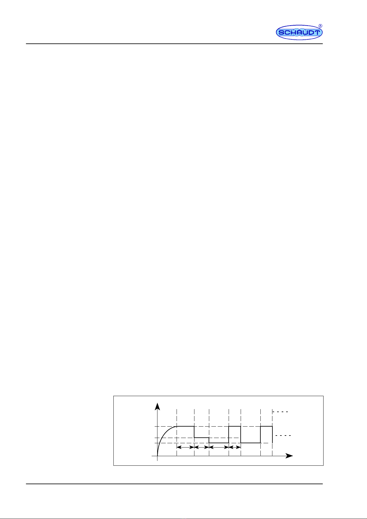
Charge curve IUoU (in 5 phases)
End of charge voltage between 14.3 V and 14.8 V
Charge current 28 A in the entire mains voltage range,
limited electronically
Voltage for float charge between 13.2 V and 13.8 V (depending on
battery type), with automatic
switchover
New charge cycle, with battery voltage below 13.2 V
Switchover to main charge and 13.8 V (depending on battery type)
with a couple of seconds delay
Ucharge
V
UVL
UEL
UR
t
tVL tRtF
tEL
Fig. 5 Example of the charging voltage curve with the CSV 416 power supply
Dimensions
Weight
Casing
Base plate
Mains connection
Current consumption
Suitable batteries
Standby current from
Caravan battery
Current-carrying
capacity
Battery charging
caravan battery
connected to mains
Operating Instructions Caravan-charging system CSV 416
15
Date: 30.05.2021
8050111 BA / EN
I (”Bulk”)
Main charge with maximum 20 A charging current, electronically limited, up
to end-of-charge voltage UVL. Start of charge also for completely discharged
batteries.
Uo (”Absorption”)
Automatic switchover to full charging with constant voltage UVL. The dura-
tion of the full charge phase is based on the battery type (is set from an EBL
... control panel connected). This sets a full charge time and minimal charge
current.
U (”Float”)
Automatic switchover to trickle charging with constant UEL. In the trickle
charge phase, a constant voltage is applied to the charger module output.
U (”Standby”)
Further reduction of charge voltage to UR. This phase lasts time tR.
U (”Refresh”)
A refresh with full charge voltage UVL for time tFis started once idle phase
time tRhas expired.
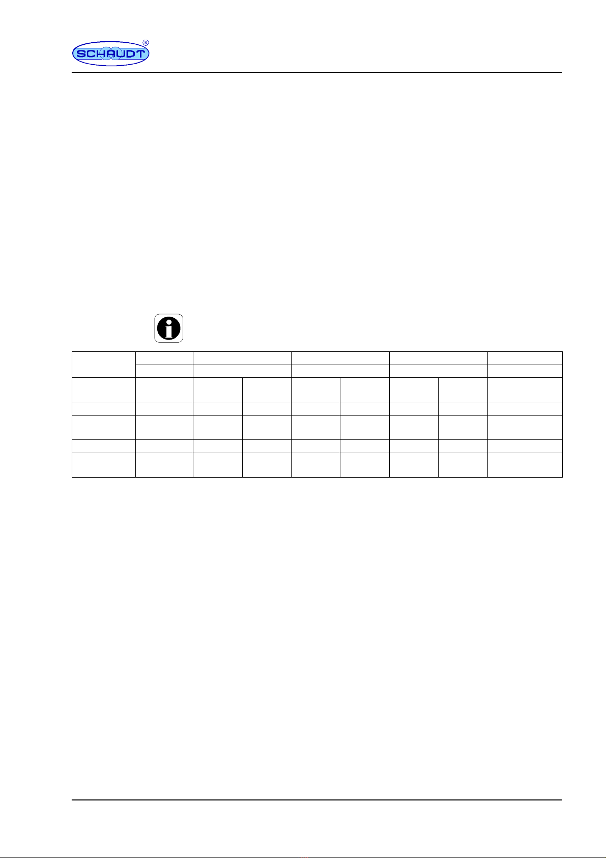
YAll voltages and times are dependent on the battery type used. These
parameters are set automatically by setting the correct battery type:
Phase 1 Phase 2 Phase 3 Phase 4 Phase 5
I (”Bulk”) Uo (”Absorption”) U (”Float”) U (”Standby”) U (”Refresh”)
Battery
type
Imax UVL tVL UEL tEL URtRtF
Lead-acid 28 A 14.40 V 4 hour 13.40 V 72 hour 13.00 V 120 hour 1 hour
Lead-gel/A
GM1 28 A 14.40 V 8 hour 13.80 V 72 hour 13.20 V 120 hour 1 hour
AGM 2 28 A 14.70 V 4 hour 13.70 V 72 hour 13.20 V 120 hour 1 hour
LiFePo4* 28 A 14.40 V 2 hour 13.80 V contin-uo
us -- -- --
* Only batteries with their own battery management system fitted may be
used.
6.3 Environmental parameters
-20 Cto+45C
-20 Cto+70C
IP 20
Operation in dry environment only
CE mark
7Maintenance
The CSV 416A caravan charging system requires no maintenance.
Clean the caravan charging system using a soft, slightly damp cloth and mild
detergent. Never use spirit, thinners or similar substances. Do not allow fluid
to ingress the caravan charging system.
No part of this manual may be reproduced, translated or copied without
express written permission.
Operating temperature
Storage temperature
Protection rating
Humidity
Yes
Cleaning
E

Operating Instructions Caravan-charging system CSV 416
16 Date: 30.05.2021 8050111 BA / EN
Appendix
A EC Declaration of Conformity
Schaudt GmbH hereby confirms that the design of the CSV 416A caravan
charging system complies with the following relevant regulations:
The original EC declaration of conformity is available for reference at any
time.
Schaudt GmbH, Elektrotechnik & Apparatebau
Planckstraße 8
88677 Markdorf
Germany
B Special fittings/accessories
Schaudt solar charger LR ... model for solar modules with a total current of
14A, including 0.5 m connection cable and connector plug
C Customer service
Schaudt GmbH, Elektrotechnik & Apparatebau
Planckstraße 8
88677 Markdorf, Germany
Phone: +49 7544 9577-16 Email: kundendienst@schaudt-gmbh.de
Website: www.schaudt-gmbh.de
Returning a faulty device:
"Always use well-padded packaging.
"Complete and enclose the fault report, see Appendix D.
"Send it to the addressee (free delivery).
Manufacturer
Address
Solar-
charge
regulator
Customer
service
Send in
device

Operating Instructions Caravan-charging system CSV 416
17
Date: 30.05.2021
8050111 BA / EN
D Fault report
In the event of damage, please fill in the fault report and send it with the
faulty device to the manufacturer.
Device type: _______________________
Part no.: _______________________
Vehicle: Manufacturer: _______________________
Model: _______________________
Own installation? Yes -No -
Upgrade? Yes -No -
Upstream overvoltage protection? Yes -No -
Following fault has occurred (please tick):
-Electrical consumers do not work -- which?
(please specify below)
-Switching on and off not possible
-Persistent fault
-Intermittent fault/loose contact
Other comments:

Operating Instructions Caravan-charging system CSV 416
18 Date: 30.05.2021 8050111 BA / EN
E Block diagram/wiring diagram
Shunt*
14.3V/28A
switch mode
3G1.5
L=1.2m
230V ~ 50Hz
to
CSV 416 ST
S 1208-x
Booster
* AHK assignment of the towing vehicle / caravan connector as
per EN 1648-1. Connectors AHK 9 and AHK 10 must be fused
external within the vehicle (max. 15A).
LF-PA401, 4-way
30A
Main
s
SCSV 416
30A
10A
10A
5A
5A
12V on
PolySwitch
PolySwitch
5A
PolySwitch
15A
2.5A
PolySwitch
15A
15A
10A
15A
10A
CSV 416
CSV 416 ST
0.4A
BUS
GND
+12V
Charge signal
Ser.
bus
Ser.
bus
BUS
GND
+12V
Battery-
types (4)
to
S1208
Molex Microfit 3F
Molex Microfit 3F
Molex Microfit 5F
Molex Microfit 6F
full
3/4
1/2
1/4
Base
full
3/4
1/2
1/4
Base
n.c.
AW
FW
Circuit-
Output
Wat. tap
KS contr.
Rast5 - 4-pin
Rast5 - 2-pin
Rast5 - 2-pin
1+
2+
3+
D+ +
+
S
+
--
15A
15A
15A
+ AHK 10*
+AHK9*
-- AHK 13*
+ KS compressor
Molex MiniFit SR-2f
Molex MiniFit SR-2f
+ Caravan-
-- Battery
max. 40A
Solar-
charge
regulator
LR ...
Solar-
module
+
--
+
--
+
--
+
+
+
--
+
+
--
+
+
--
+
--
+
+
--
+
--
+
--
+
--
Heater
Pump
WC
Circuit 1
Circuit 2
Circuit 3
Awning light
TV
Circuit 4
Circuit 5
Spare
Plug connector LF-PA 401
6.3x0.8 - 26-way
(*from 05/2021)
Table of contents
Other Schaudt Automobile Accessories manuals


