Schaudt CSV 410 User manual

Date: 20.02.2020
ESchaudt GmbH, Elektrotechnik und Apparatebau, Planckstraße 8, 88677 Markdorf, Germany, Tel. +49 7544 9577-0, Fax +49 7544 9577-29, www.schaudt--gmbh.de
8050102 BA / EN
Instruction Manual
Caravan-charging system CSV 410
Contents
1 Introduction 2............................................
2 Safety information 2......................................
2.1 Meaning of the safety signs 2..............................
2.2 General safety instructions 2...............................
3 Application and function 3.................................
3.1 Battery functions 5........................................
3.2 Additional functions 5.....................................
4 Layout 6................................................
5 Operation 7..............................................
5.1 Switching on and off 7.....................................
5.2 Starting up the system 8...................................
5.3 Changing the battery 9....................................
5.4 Faults 10.................................................
5.5 Shutting down the system 11................................
5.6 Closing down the system 11................................
6 Technical details 12........................................
6.1 Mechanical details 12......................................
6.2 Electrical details 12........................................
6.3 Environmental parameters 13...............................
7 Maintenance 13...........................................
Appendix 14..............................................
Operating manual for caravan-charging system CSV 410
2Date: 20.02.2020 8050102 BA / EN
1 Introduction
This instruction manual contains important information for the safe operation
of equipment supplied by Schaudt. Make sure you read and follow the safety
instructions provided.
The instruction manual should always be kept in the vehicle. All safety infor-
mation must be passed on to other users.
2 Safety information
2.1 Meaning of the safety signs
YDANGER!
Failure to comply with this sign may result in danger to life or physical con-
dition.
YWARNING!
Failure to comply with this sign may result in injury.
YCAUTION!
Failure to comply with the sign may result in damage to equipment or other
connected loads.
YThis symbol references recommendations or special features.
2.2 General safety instructions
The design of the device is state-of-the-art and complies with approved sa-
fety regulations. Failure to observe the safety instructions may nonetheless
lead to injury or damage to the device.
Only use the device when it is in perfect technical condition.
Any faults impacting the safety of persons or the proper functioning of the
device must be repaired immediately by specialists.
YDANGER!
230V units carrying mains voltage.
Risk of fatal injury due to electric shock or fire:
FThe motorhome or caravan’s electrical system must comply with DIN,
VDE and ISO regulations.
FNever try to modify the electrical system.
FDo not try to modify the device.
FOnly qualified electricians are permitted to make the electrical connec-
tions in accordance with the installation instructions supplied by
Schaudt.
FConnection work may only be carried out after the power has been
disconnected.
FNever try to start the device using a defective mains cable or a faulty
connection.
FNever undertake maintenance on the device when it is live.
Operating manual for caravan-charging system CSV 410
3
Date: 20.02.2020
8050102 BA / EN
YDANGER!
Incorrect installation
Electric shock or damage to connected devices:
FInstall as shown in installation instructions.
FThe mains connection line may only be replaced by an authorised cu-
stomer service department or by those qualified.
YWARNING!
Hot components
Burns:
FBlown fuses may only be changed after the power to the system has
been disconnected.
FBlown fuses may only be replaced once the cause of the fault is
known and has been rectified.
FNever bypass or repair fuses.
FThe back of the device can get hot during operation. Do not touch it.
FOnly use original fuses rated as specified on the device.
FNever store heat sensitive objects close to the device (e.g. tempera-
ture sensitive clothes if the device has been installed in a wardrobe).
3 Application and function
YThis device is not intended to be used by persons (including children)
with limited physical, sensory or mental aptitude or lack of experience
and/or knowledge unless they are supervised by a person responsible for
their safety or have received instruction from this person as to how the
device is used.
Children must be supervised to ensure they do not play with the device.
This device is intended for installation into a vehicle.
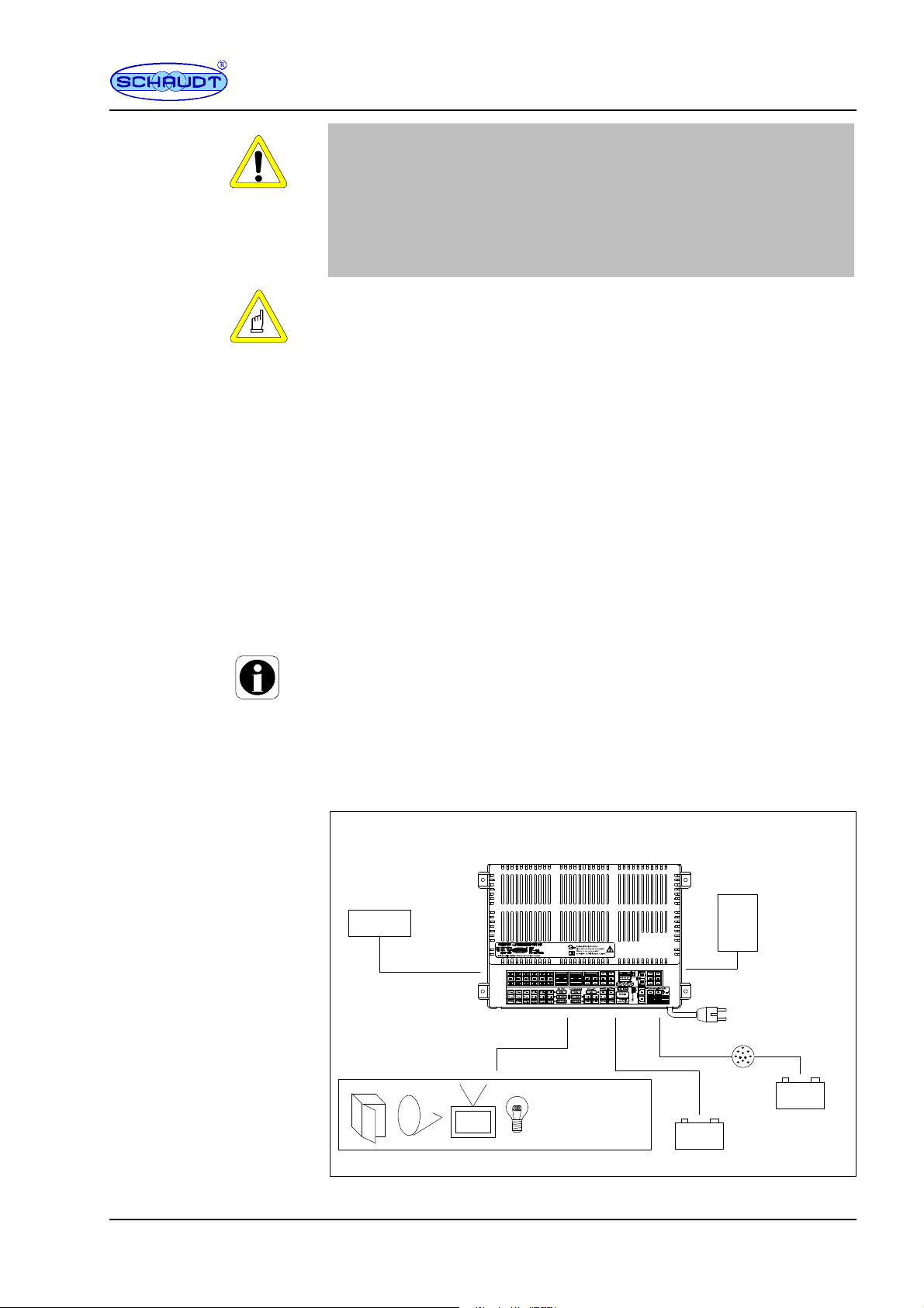
CSV 410
+--
+--
Caravan charging system
230V AC
12V consumers Caravan battery
Starter battery
Lighting
Pump
Heater
etc.
LR ...
Solar regulator
(accessory)
Towing vehicle
Control and
switch panel model
ST or LT
Fig. 1 On-board power supply system

Operating manual for caravan-charging system CSV 410
4Date: 20.02.2020 8050102 BA / EN
The CSV 410 caravan charging system is the central power supply unit for
all 12 V consumers connected to the caravan’s electrical system. It is usually
located in a cupboard or storage area and is accessible from the front in or-
der to change fuses.
The caravan charging system has been designed solely for connecting to a
12 V onboard supply.
Connected units can be supplied from the caravan battery or the towing ve-
hicle’s battery if a mains supply is not available.
Because the device provides a hum-free, stabilised output voltage, sensitive
consumers such as transistor lights and radios can be connected and powe-
red.
The CSV 410 caravan charging system consists of:
Fa charge module for charging all connected batteries
Fthe complete 12V distribution system
Ffuses for the 12V circuits
Fa battery booster
An ST ... switch panel must be installed as a minimum to run the system.
Connections are provided for:
FSolar charge regulator
FControl and display panel
Flat vehicle fuses protect the various circuits.
FExcess temperature
FOverload
FShort circuit
230V AC 10%, 47 -- 63 Hz sinusoidal, protection class I
12V outputs may only be loaded up to a maximum of 90% of the rated cur-
rent of the associated fuse (see block diagram or nameplate).
Modules
Required
control circuits
Protective circuits
Mains connection
Current-carrying
capacity

Operating manual for caravan-charging system CSV 410
5
Date: 20.02.2020
8050102 BA / EN
3.1 Battery functions
6-cell lead acid or lead gel batteries, 80 Ah and above
Charging the caravan battery whilst driving; increasing the supply voltage
coming from the towing vehicle via the battery booster
The 12 V main switch (rocker switch with centre position on the control and
switch panel) disconnects all the 12 V consumers from the caravan battery
(exception: the fridge controller electronics).
This prevents the caravan battery from being slowly discharged by standby
currents.
The batteries can still be charged using the caravan charging system, the
towing vehicle or the solar charger, even when the main battery switch is
OFF.
The switching option provided by the battery selector switch ensures opti-
mum charging of the two battery types, lead gel and lead acid.
The consumers are switched off (except for the refrigerator) when the cara-
van is hitched to the towing vehicle and the ignition is switched on (power on
terminal 10 and trailer hitch TH). Consumers can be switched on again at
any time (the automatic disconnector does not prevent this).
No standby current when towing vehicle ignition is off; additional current con-
sumption by the fridge’s control electronics (see documentation supplied by
the fridge manufacturer);
Measured when all the consumers inside the caravan are switched off.
Caravan battery
Characteristic charging curve IUoU
End of charge voltage 14.4V*
Charging current 28 A
Voltage for float charge 13.7V* with automatic switch function
*Until 03/2020:
Final charging voltage 14,3 V; trickle charge voltage 13,8 V
Charging current typ. 8 A
3.2 Additional functions
This output supplies the control electronics of a fridge:
FFrom the caravan battery
FFrom the towing vehicle’s battery when the ignition is switched on
FFrom the mains supply when it is connected up
YThe refrigerator only operates on 12 V when the caravan is hitched to the
towing vehicle and the ignition is switched on.
Suitable batteries
Battery charging
whilst moving
12V main switch
Battery selector switch
Automatic disconnector
Standby current from
towing vehicle battery
Battery charging via
mains connector
Battery charging via
towing vehicle operation
Refrigerator controller

Operating manual for caravan-charging system CSV 410
6Date: 20.02.2020 8050102 BA / EN
YCAUTION!
Total discharge.
Damages the caravan battery/towing vehicle battery:
FAvoid continuous 12V operation. The refrigerator only operates on 12
V when the caravan is hitched to the towing vehicle and the ignition is
switched on.
Maximum permitted charge current 14 A, protected with 15 A
4 Layout
1
1312
1110
2
3
4
5 6 8 9 14 15 16 17 18 19 20 21 22
24
25
26
237
Fig. 2 Front view of CSV 410 caravan charging system
1 Connections for circuit 5 14 Flat vehicle fuse for fridge controller
2 Connections for circuit 3 15 Connections for circuit 2
3 Pump connections 16 Connections for circuit 1
4 Adhesive label 17 Fridge controller connection
5 Bracket with hole 18 Connector for solar charge regulator LR ...
6 Switch 1 and 2 pump connections 19 Indicator and control connections
7 Adhesive label 20 Solar flat fuse
8 Flat vehicle fuse for circuit 5 21 Selector switch for lead/gel/lead-acid battery
9 Flat vehicle fuse for circuit 3 22 Caravan battery connection
10 Flat vehicle fuse for pump 23 Mains cable
11 Flat vehicle fuse for charger module 24 Trailer hitch plugin connection
12 Flat vehicle fuse for circuit 1 25 Refrigerator supply connection
13 Flat vehicle fuse for circuit 2 26 Casing
Battery charging with
solar charging regulator
Operating manual for caravan-charging system CSV 410
7
Date: 20.02.2020
8050102 BA / EN
5 Operation
The caravan charging system is operated solely from the control and switch
panel connected.
The CSV 410 caravan charging system does not require daily operation.
Initial setting is only needed after the type of battery (lead-acid or lead-gel)
has been changed or during commissioning or when upgrading with acces-
sories (see Section 5.3 and CSV 410 installation instructions).
5.1 Switching on and off
5.1.1 Control and switch panels of type LT ...
Control and switch panels of type LT ... are supplied with a separate opera-
ting manual (kept with the vehicle). Please refer to this manual for instruc-
tions on operation.
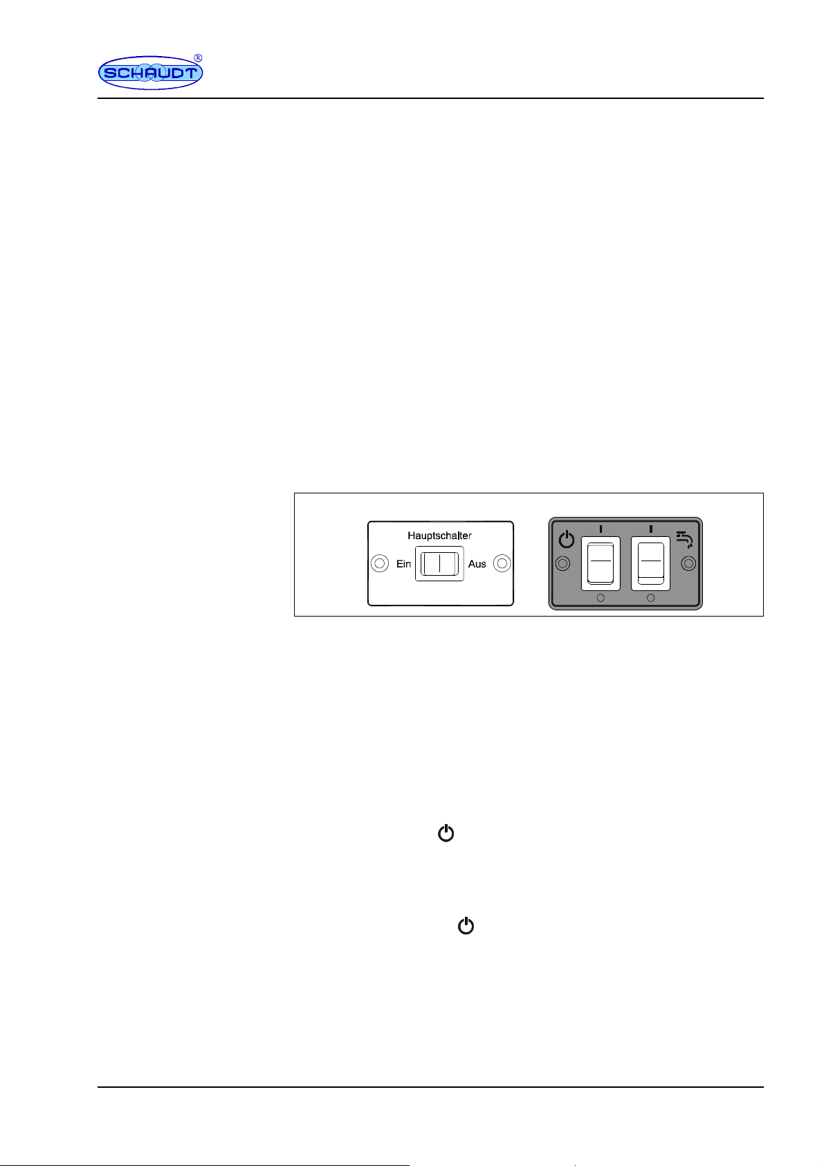
5.1.2 Switch panel ST02 or ST05HS+PU
ST05 ST02HS+PU (option)
Fig. 3 Switch panels ST05 and ST02HS+PU
In the simplest case, an ST05 switch panel is connected to the caravan
charging system. It only has one rocker switch with a centre position. The
optional ST02HS+PU also has a pump switch.
The 12V supply of the living area is switched on using the button. Excep-
tions:
FCompressor/AES-refrigerator-control unit
These consumers are still operable even when the 12V power supply is swit-
ched off.
Press rocker switch (12V main switch) so that it is briefly in the ”I” po-
sition (ON).
F
The 12V supply to the living area is now switched on.
Press 12V main switch so that it is briefly in the ”O” position (OFF).
The 12V supply to the living area is now switched off.
Switching on
Switching off

Operating manual for caravan-charging system CSV 410
8Date: 20.02.2020 8050102 BA / EN
5.1.3 Connect pump (option)
For the pump to be switched on, the 12V supply voltage must first be swit-
ched on (see Section 5.1.2 for the main supply).
Move the switch with the pump symbol upwards.
The supply voltage for the water pump is enabled:
FThe pump may switch on briefly (e.g. in a pressure system).
FIn other systems, the pump is enabled by the water tap contacts.
Move the switch with the pump symbol downwards.
5.2 Starting up the system
YCAUTION!
Incorrect settings on the caravan charging system.
Damage to connected devices. Therefore prior to starting:
FEnsure that the battery selector switch (Fig. 2, Pos. 21) is set to the
correct position for the battery installed.
Press rocker switch (12V main switch) so that it is briefly in the ”I” po-
sition (ON).
The 12 V main switch switches all consumers on and off (exception: the
fridge controller electronics).
YCAUTION!
Exceeding the thresholds of the 230V mains supply.
Will damage the caravan charging system, 12 V consumers or other con-
nected devices:
FDo not connect a generator until it is running smoothly.
FIt is essential that the generator conforms to the specifications of the
mains supply.
FDo not connect the caravan charging system to the onboard mains
voltage on car ferries (non-problematic mains voltage cannot always
be guaranteed on car ferries).
The use of an upstream overvoltage protection device is recommen-
ded.
YCAUTION!
No battery buffer function
Damage to connected devices:
FDo not operate solar regulator without battery connected.
Switching on
Switching off
12V main switch
Generator operation and
passenger vehicle
ferries
Operation with solar
regulator

Operating manual for caravan-charging system CSV 410
9
Date: 20.02.2020
8050102 BA / EN
YCAUTION!
Battery discharge
Towing vehicle can no longer start:
FSwitch off the ignition when the towing vehicle is stationary.
5.3 Changing the battery
YCAUTION!
Use of incorrect battery types or incorrectly rated batteries.
Will damage the battery or the devices connected up to the caravan char-
ging system:
FBatteries should only be changed by qualified personnel.
FFollow the battery manufacturer’s instructions.
FThe caravan charging system is to be used solely for connecting the
12 V power supply to 6-cell lead-gel or lead-acid batteries. Never use
non-approved battery types such as NiMH batteries.
YNormally only batteries of the same type and capacity should be used,
i.e. the same as those installed by the manufacturer.
YIt is possible to swap lead acid batteries with lead gel batteries. You can-
not change over from lead-gel to lead-acid batteries. Contact the vehicle
manufacturer for more information.
Disconnect the battery from the caravan charging system by switching
the 12 V main switch off.
Unhitch the caravan from the towing vehicle.
Replace battery.
After changing the battery, recheck which type of battery has been inser-
ted.
YDANGER!
Incorrect setting of the battery selector switch.
Risk of explosion due to build up of explosive gases:
FMove the battery selector switch to the correct position.
YCAUTION!
Incorrect setting of the battery selector switch.
Damage to the battery.
FMove the battery selector switch to the correct position.
Disconnect the caravan charging system from the mains before resetting
the battery selector switch.
Move the battery selector switch (Fig. 2, Pos. 21) to the correct position
using a thin object (e.g. a ballpoint pen):
FLead gel battery: Set the battery selector switch to ”Lead-gel”.
FLead acid battery: Set the battery selector switch to ”Lead-acid”.
Start up the system as described in Section 5.2.
Operation on towing
vehicle
Changing the battery
Starting up
the system
Operating manual for caravan-charging system CSV 410
10 Date: 20.02.2020 8050102 BA / EN
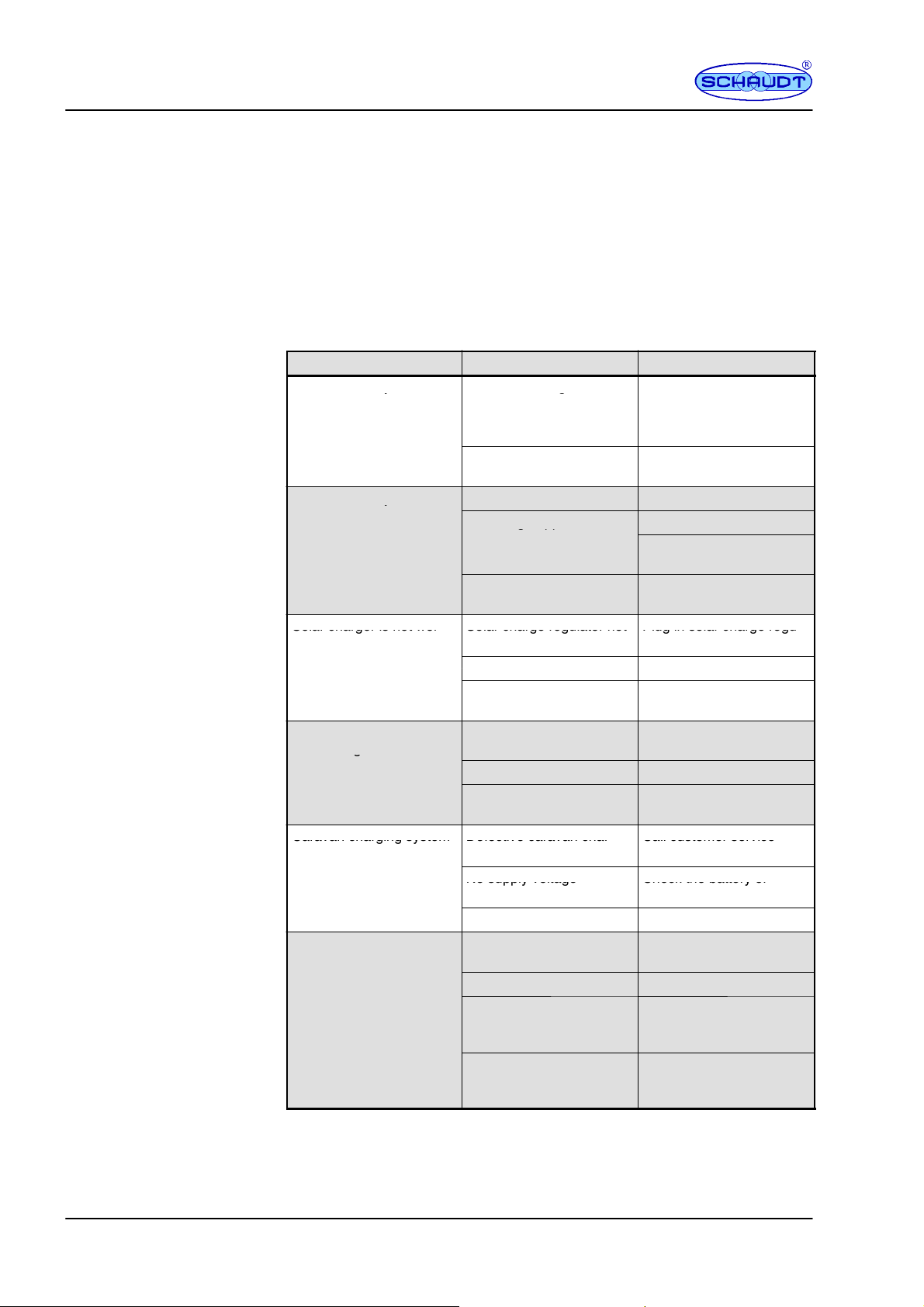
5.4 Faults
A fault in the power supply system is usually caused by a blown fuse.
Please contact our customer service address if you cannot rectify the fault
using the following table.
If this is not possible, e.g. if you are abroad, you can have the caravan char-
ging system repaired at a specialist workshop. In this case, you must ensure
that the warranty is not invalidated by incorrect repairs being carried out.
Schaudt GmbH will not accept any liability for damage resulting from such
repairs.
Fault Possible cause Remedy
Caravan battery is not
h
d
d
i
2
3
0
V
No mains voltage Switch on the automatic
i
i
b
k
i
h
h
i
y
charged during 230 V
o
p
e
r
a
t
i
o
n
g
circuit breaker in the vehi-
c
l
e
;
c
h
e
c
k
t
h
e
m
a
i
n
s
v
o
l
-
o
p
e
r
a
t
i
o
n
c
l
e
;
c
h
e
c
k
t
h
e
m
a
i
n
s
v
o
l
-
tage
Defective caravan char-
ging system
Call customer service
Caravan battery is not
h
d
h
i
l
d
i
i
Defective alternator Check the alternator
y
charged whilst driving No voltage applied to
”
I
i
i
O
N
”
i
Check the fuse and wiring
g
p
p
”Ignition ON” input or per-
manent plus Check the towing vehicle
plug connection
Defective caravan char-
ging system
Call customer service
Solar charger is not wor- Solar charge regulator not Plug in solar charge regu-
S
o
l
a
r
c
h
a
r
g
e
r
i
s
n
o
t
w
o
r
king (mains supply off)
S
o
l
a
r
c
h
a
r
g
e
r
e
g
u
l
a
t
o
r
n
o
t
plugged in
P
l
u
g
i
n
s
o
l
a
r
c
h
a
r
g
e
r
e
g
u
lator
D
e
f
e
c
t
i
v
e
f
u
s
e
o
r
w
i
r
i
n
g
C
h
e
c
k
f
u
s
e
a
n
d
w
i
r
i
n
g
D
e
f
ect
i
ve
f
use or w
i
r
i
ng
C
h
ec
k
f
use an
d
w
i
r
i
ng
Solar charge regulator de-
fective
Check solar charge regu-
lator
1
2
V
s
u
p
p
l
y
d
o
e
s
n
o
t
w
o
r
k
1
2
V
m
a
i
n
s
w
i
t
c
h
i
s
s
w
i
t
-
1
2
V
m
a
i
n
s
w
i
t
c
h
m
u
s
t
b
e
1
2
V
supp
l
y
d
oes no
t
wor
k
i
n
t
h
e
l
i
v
i
n
g
a
r
e
a
1
2
V
ma
i
nsw
i
t
c
h
i
ssw
i
t
-
c
h
e
d
o
f
f
1
2
V
ma
i
nsw
i
t
c
h
mus
t
b
e
s
w
i
t
c
h
e
d
o
n
in the living area ched o
f
f
switched on
g
D
e
f
e
c
t
i
v
e
f
u
s
e
o
r
w
i
r
i
n
g
C
h
e
c
k
f
u
s
e
a
n
d
w
i
r
i
n
g
D
e
f
ect
i
ve
f
use or w
i
r
i
ng
C
h
ec
k
f
use an
d
w
i
r
i
ng
Defective caravan char-
ging system
Call customer service
Caravan charging system Defective caravan char- Call customer service
C
a
r
a
v
a
n
c
h
a
r
g
i
n
g
s
y
s
t
e
m
cannot be switched on
i
t
h
k
i
t
h
D
e
f
e
c
t
i
v
e
c
a
r
a
v
a
n
c
h
a
r
ging system
C
a
l
l
c
u
s
t
o
m
e
r
s
e
r
v
i
c
e
using the rocker switch No supply voltage Check the battery or
N
o
s
u
p
p
l
y
v
o
l
t
a
g
e
C
h
e
c
k
t
h
e
b
a
t
t
e
r
y
o
r
mains connection
Rocker switch is defective Call customer service
Pump will not switch on 12V main switch is swit-
ched off
12V main switch must be
switched on
Pump switch disabled Turn on pump switch
For immersion pumps:
Contact in the water tap of
pump defective
Contact a dealer.
For pressure pumps: Pres-
sure switch or pump de-
fective
Contact a dealer.
Flat vehicle fuses
Operating manual for caravan-charging system CSV 410
11
Date: 20.02.2020
8050102 BA / EN
RemedyPossible causeFault
Pump will not switch on If only one ST02 switch
panel is connected, there
must be a jumper between
pins 8 and 6 on the CSV
410 on the connector to
the panel (Fig. 2, Pos. 19).
This may be missing.
Contact a dealer.
Defective caravan char-
ging system
Call customer service
YThe charging current is reduced automatically if the device becomes too
hot due to excessive ambient temperature or lack of ventilation. Always
prevent the device from overheating nevertheless.
5.5 Shutting down the system
Press the rocker switch (12 V main switch) so that it is briefly in the
”OFF” position.
5.6 Closing down the system
YCAUTION!
Total discharge.
Damages the caravan battery:
FFully charge the caravan battery before and after closing down the
system. Connect a vehicle with an 80 Ah battery and a vehicle with a
160 Ah battery to the mains for at least 24 and 36 hours respectively.
YCAUTION!
Permitted input voltages exceeded.
Damage to connected consumers:
FDo not operate any connected Schaudt solar charge regulator without
battery.
FWhen the battery is changed or removed, first unplug the ”+ solar cell”
connector on the solar charge regulator.
Fully charge the caravan battery before closing down the system.
The caravan battery is then protected against total discharge. This only ap-
plies if the battery is intact. Follow the battery manufacturer’s instructions.
Fully charge the caravan battery before closing down the system.
Remove the clamps from the battery terminals.
Remove the ”+ solar cell” connector on the solar charge regulator.
Closing down the
system for up to
6 months
Closing down the
system for more than
6 months

Operating manual for caravan-charging system CSV 410
12 Date: 20.02.2020 8050102 BA / EN
6 Technical details
6.1 Mechanical details
111 x 320 x 217 (H x W x D in mm), including attachment feet
2kg
PA (polyamide), gentian blue (RAL 5010)
6.2 Electrical details
230V AC 10%, 47 -- 63 Hz sinusoidal, protection class I
3.2 A
6-cell lead acid or lead gel batteries, 80 Ah and above
Without control and switch panel: 0 mA, plus consumption of refrigerator
control electronics;
With control and switch panel (e.g. LT310/LT409): approx. 2 -- 3 mA, plus
consumption of controller electronics of refrigerator
Conditions for the measurement:
FApprox. 10 minutes after mains isolation without mains connection
F12.6V battery voltage
FBattery alarm OFF
FAll consumers switched off
F12V main switch off
12V outputs A maximum of 90% of the nominal cur-
rent
of the relevant fuse may be
drawn.
Caravan battery
Charging curve IUoU
Final charging voltage 14.4 V
Charge current 28 A in the entire mains voltage range,
electronically limited, minus the
charge current into the towing vehicle bat-
tery
Voltage for float charge 13.7 V with automatic switchover
New charge cycle, with battery voltage below 13.7 V
Switchover to main charging with approx. 5 seconds delay
Main charge
I
Full charge
Uo
Trickle charge
U
4 h for lead--acid
16 h for lead--gel
Time
14.4
13.7
Ucharge
V
Fig. 4 Example of the charge voltage behaviour with the CSV 409 A caravan charging sy-
stem
Dimensions
Weight
Casing
Mains connection
Current consumption
Suitable batteries
Standby current from
Caravan battery
Current--carrying
capacity
Battery charging via
mains connector

Operating manual for caravan-charging system CSV 410
13
Date: 20.02.2020
8050102 BA / EN
I Main charge with maximum 28 A charging current, electronically limi-
ted, up to final charging voltage. The battery is now charged up to ap-
prox. 80%. Start of charge also for completely discharged batteries.
Uo Automatic changeover to full charge with constant 14.4 V. The duration
of the full charge phase depends on the type of battery and is configu-
red on the device: Lead-acid batteries, 4 hour, lead-gel batteries, 16
hours.
U Automatic changeover to compensation charge with constant 13.7V. In
the compensation charge phase, the voltage at the output of the char-
ging module is constant. The battery is now charged up to approx.
95%.
Start of a new charging cycle by switching over to main charge, if the battery
voltage falls below 13.7V for more than 5 seconds when loaded. Start of
charge also for completely discharged batteries. The internal charger mo-
dule can also be operated without the caravan battery.
Max. permitted charging current 14 A, protected by 15 A fuse
Simultaneous charging of caravan battery by alternator
Maximum charge current
to caravan battery 8 A, electronically restricted
6.3 Environmental parameters
-10 Cto+40C
-20 Cto+70C
Operation in dry environment only
CE mark?
7Maintenance
The CSV 410 caravan charging system requires no maintenance.
Clean the caravan charging system using a soft, slightly damp cloth and mild
detergent. Never use spirit, thinners or similar substances. Do not allow fluid
to ingress the caravan charging system.
No part of this manual may be reproduced, translated or copied without ex-
press written permission.
Battery charging via
solar charge regulator
Battery charging
whilst moving
Operating temperature
Storage temperature
Humidity
Yes
Cleaning
E

Operating manual for caravan-charging system CSV 410
14 Date: 20.02.2020 8050102 BA / EN
Appendix
A EC Declaration of Conformity
Schaudt GmbH hereby confirms that the design of the device complies with
the relevant regulations.
The original EU conformity declaration is available and can be referred to at
any time.
Schaudt GmbH, Elektrotechnik & Apparatebau
Planckstrasse 8
88677 Markdorf
Germany
B Special fittings/accessories
Schaudt solar charger LR ... model for solar modules with a total current of
14A, including 0.5 m connection cable and connector plug
C Customer service
Schaudt GmbH, Elektrotechnik & Apparatebau
Planckstraße 8
D-88677 Markdorf
Phone: +49 7544 9577-16 e-mail: kundendienst@schaudt-gmbh.de
Office hours Mon to Thurs 08.00 -- 12.00, 13.00 -- 16.00
Fri 08.00 -- 12.00
Returning a faulty device:
Always use well-padded packaging.
Complete and enclose the fault report, see Appendix D.
Send it to the addressee (free delivery).
Manufacturer
Address
Solar charge regulator
Customer service
address
Send in device

Operating manual for caravan-charging system CSV 410
15
Date: 20.02.2020
8050102 BA / EN
D Fault report
In the event of damage, please fill in the fault report and send it with the
faulty device to the manufacturer.
Device type: _______________________
Item no.: _______________________
Vehicle: Manufacturer: _______________________
Model: _______________________
Own installation? Yes -No -
Upgrade? Yes -No -
Upstream overvoltage protection? Yes -No -
There is the following defect:
Other comments:
no
Battery-
charge during mobile
operation
no
Battery-
charge during mains
operation
Voltage Current
Permanent fault
Intermittent fault/loose
contact
The following electrical
consumers do not work:
Cannot switch on/off

Operating manual for caravan-charging system CSV 410
16 Date: 20.02.2020 8050102 BA / EN
E Block diagram/wiring diagram
230V~50Hz
Plug--in cable
L = 1.2m
3G1.5
6.3 x 0.8 Switch Mode
CSV 409
14.3V/28A
lead acid
lead gel/
Change--over switch
S 1218
Negative
+
Solar module
charge
Solar
LRS 1214 Circuit-
stage
Disconn.
automatic
PTC
max. 0.4A
+Ua booster
14.25V
3F MNL socket
* Connections 9 and 10 must be fused ext. in
the vehicle up to a maximum of 15A.
910
...
* Trailer hitch towing vehicle/ caravan connecting
plug assignment as per EN 1648-1
+
-- Fr cartridge; fuse fitted in vehicle
-- T H
+ TH TH +12V perm. plus *
9
13 Negative to9
11
10
-- T H
+TH
Fridge controller
+
--
Negative to
TH +12V connected *
10
Caravan battery
+
Molex Minifit SR--2F
--
max. 40 A
12V OFF
12V ON
12V indicator
Mains indicator
+
-- 12V
nc
Pump
To the panel
--
+Pump
Water tap 1
Water tap 2
Circuit 3
Circuit 2
Circuit 1
+
--
--
+
--
+
+
--
--
+
--
+
+
--
TV
+
--
--
+Awning light
--
+Spare
Plug connector LF--PA 401
6.3
x
0.8
(
32 wa
y
)
MSFQ/0 8F pin strip
Circuit 5
Booster
regulator
Table of contents
Other Schaudt Automobile Accessories manuals


Popular Automobile Accessories manuals by other brands


Pioneer
Pioneer CA-HM-HYU.001OEM installation manual

Aerpro
Aerpro VE 2 Series Installation & user manual

Lippert Components
Lippert Components Edge installation manual

Prorack
Prorack K1206 manual

rough country
rough country HEC70186 installation instructions

Extang
Extang CLASSIC PLATINUM & BLACKMAX 7920 Installation sheet


