Schaudt EBL 226 C +OVP User manual
Date: 30.09.2009
ESchaudt GmbH, Elektrotechnik und Apparatebau, Planckstraße 8, 88677 Markdorf, Germany, Tel. +49 7544 9577-0, Fax +49 7544 9577-29, www.schaudt--gmbh.de
811.573 BA / EN
Instruction Manual
R
Electrobloc EBL 226 C +OVP
Table of contents
1 Safety Information 2......................................
1.1 Meaning of safety symbols 2...............................
1.2 General safety information 2...............................
2 Introduction 3............................................
3 Operation 3..............................................
3.1 Switching System on/off 3.................................
3.2 Changing the Battery 4....................................
3.3 System Faults 5..........................................
3.4 Closing down the System 7................................
4 Application and Functions in Detail 8........................
4.1 Battery Functions 9.......................................
4.2 Additional Functions 10.....................................
5 Maintenance 10...........................................
Appendix 11..............................................

Instruction Manual Electrobloc EBL 226 C +OVP
2
Date: 30.09.2009 811.573 BA / EN
1 Safety Information
1.1 Meaning of safety symbols
Y
DANGER!
Failure to heed this warning may result in death or serious injury.
Y
WARNING!
Failure to heed this warning may result in personal injuries.
Y
ATTENTION!
Failure to heed this warning may result in damage to the device or connec-
ted consumers.
1.2 General safety information
The device is state-of-the-art and complies with approved safety regulations.
Nonetheless, personal injuries or damage to the device may occur if the sa-
fety instructions contained herein are not followed.
Ensure that the device is in perfect working order before use.
Any technical faults which may have an adverse effect on personal safety or
device safety must be rectified immediately by qualified personnel.
Y
DANGER!
230 V mains voltage carrying parts.
Danger of death due to electric shock or fire:
F
Do not carry out maintenance or repair work on the device.
F
If cables or the device housing are damaged, no longer use the
device and isolate from the power supply.
F
Ensure that no liquids enter the device.
Y
WARNING!
Hot components!
Burns:
F
Only replace blown fuses when the device is completely de-energised.
F
Only replace blown fuses once the cause of the fault has been identi-
fied and rectified.
F
Never bypass or repair fuses.
F
Only use original fuses rated as specified on the device.
F
Device parts can become hot during operation. Do not touch.
F
Never store heat sensitive objects close to the device (e.g. tempera-
ture sensitive clothes if the device has been installed in a wardrobe).

Instruction Manual Electrobloc EBL 226 C +OVP
3
Date: 30.09.2009
811.573 BA / EN
2 Introduction
This instruction manual contains important information on the safe operation
of equipment supplied by Schaudt. Read and always follow the safety in-
structions.
The instruction manual should be kept in the vehicle at all times. Ensure that
other users are made aware of the safety regulations.
3 Operation
The electronic block is operated exclusively through the connected control
and switching board IT ... / LT ... .
Operation of the Electrobloc EBL 226 C +OVP is not required for daily use.
Settings only have to be configured once if the battery type is changed (lead
acid or lead gel), during initial start-up or when retrofitting accessories (see
chapt. 3.2 and assembly instructions EBL 226 C +OVP).
3.1 Switching system on/off
Y
ATTENTION!
Incorrect settings on the electronic block!
Connected devices may be damaged. Therefore, prior to initial start-up:
F
Ensure the living area battery is connected.
F
Ensure that the battery selector switch (Fig. 1, Pos. 1) is set to the
correct position for the inserted battery.
F
Make sure the AES fuse (Fig. 4, Pos. 2) is only used when the AES
refrigerator is connected. Otherwise, the living area battery may be to-
tally discharged. Damage to the battery is possible.
³Disable battery isolator on the DT/LT ... control and switch panel (see
operating instructions of the relevant control and switch panel).
³After enabling the battery cut-off switch or after changing batteries:
12-Briefly turn on the 12V main switch on the DT/LT ... control and switch
panel to start up the consumers.
Use the 12 V main switch (see instruction manual of relevant control and
switch panel) to switch on/off all the consumers and the control and switch
panel.
Excluded are:
F
Side marking lights
F
Heater
F
Step
F
Frost protection valve
F
AES/compressor refrigerator
12V main switch
(on DT/LT ... control and
switch panel)

Instruction Manual Electrobloc EBL 226 C +OVP
4
Date: 30.09.2009 811.573 BA / EN
F
Refrigerator control
F
Wastewater tank heating
F
Awning light
For further information, see the instruction manual of the DT/LT ... control
and switch panel .
The supply to the step is protected by a self-resetting fuse. This is why the
step switch may only be activated briefly.
Y
ATTENTION!
Activating the step switch too long results in too high a current!
Self-resetting fuse can activate:
F
Only press the step switch briefly.
³If the self-resetting fuse has triggered, it needs about one minute to reset
before the step switch can be pressed again.
Y
ATTENTION!
No battery buffer function!
Damage to connected devices:
F
Do not operate solar regulator without battery connected.
3.2 Changing the battery
Y
ATTENTION!
Use of incorrect battery types or incorrectly rated batteries.
Damage to the battery or devices connected to the electronic block:
F
Batteries should only be changed by qualified personnel.
F
Follow the instructions of the battery manufacturer.
F
Only connect the electronic block to 12 V power supplies with rechar-
geable 6-cell lead gel or lead acid batteries. Do not use any uninten-
ded battery types.
Y
Only batteries of the same type and capacity as those installed by the
manufacturer should normally be used.
Y
It is possible to swap lead acid batteries with lead gel batteries. Changing
from lead gel batteries to lead acid batteries is not possible without over-
head. Contact the vehicle manufacturer for more information.
³Electrically disconnect the battery from the Electrobloc. To do this, enable
the battery isolation on the DT/LT ... control and switch panel (see also
section 3.4).
³Remove ”+ solar cell” connector on the solar charge regulator.
³Isolate Electrobloc from the mains voltage (230V AC).
³Replace battery.
³After changing the battery, recheck which type of battery has been inser-
ted.
Step switch
Operation with solar
regulator
Changing the battery

Instruction Manual Electrobloc EBL 226 C +OVP
5
Date: 30.09.2009
811.573 BA / EN
Y
DANGER!
Incorrect setting of the battery selector switch.
Risk of explosion due to build up of explosive gases:
F
Set the battery selector switch to the correct position.
Y
ATTENTION!
Incorrect setting of the battery selector switch.
Damage to the battery.
F
Set the battery selector switch to the correct position.
³Disconnect the electronic block from the mains before adjusting the bat-
tery selector switch.
R
1
Fig. 1 Battery selector switch
³Set the battery selector switch (Fig. 1, Pos. 1) to the correct position
using a thin object (such as a ballpoint pen):
F
Lead gel battery: Set the battery selector switch to ”Lead gel”.
F
Lead acid battery: Set battery selector switch to ”Lead gel”.
³Insert ”+ solar cell” connector on the solar charge regulator.
³Start up the system as described in section 3.1.
3.3 System Faults
A fault in the power supply system is usually caused by a blown fuse.
The following is protected with a self-resetting fuse:
F
Exit step
If a fault has occurred here, the step switch must not be pressed for about
one minute. This fuse resets automatically during this period.
Please contact our customer service department if you are unable to rectify
the fault using the following table.
If this is not possible, e.g. if you are abroad, you can have the electronic bloc
repaired at a specialist workshop. Please note that the warranty will become
void if incorrect repair work is carried out. Schaudt GmbH shall not accept
liability for any damages resulting from such repairs.
Starting up
the System
Flat vehicle fuses
Self-resetting
fuses

Instruction Manual Electrobloc EBL 226 C +OVP
6
Date: 30.09.2009 811.573 BA / EN
Fault Possible cause Remedy
Living area battery is not
charged during 230 V
t
i
(
b
t
t
l
t
No mains voltage Switch on the automatic
fuse in the vehicle
g
g
operation (battery voltage
c
o
n
s
t
a
n
t
l
y
b
e
l
o
w
1
3
3
V
)
Have the mains voltage
cons
t
an
t
l
y
b
e
l
ow
1
3
.
3
V
)
H
a
v
e
t
h
e
m
a
i
n
s
v
o
l
t
a
g
e
checked
Defective electronic block Contact the customer
service department
Living area battery is
overcharged during 230 V
operation (battery voltage
constantly above 14.5 V)
Defective electronic block Contact the customer
service department
Starter battery is not No mains voltage Switch on the automatic
S
t
a
r
t
e
r
b
a
t
t
e
r
y
i
s
n
o
t
charged during 230 V
o
p
e
r
a
t
i
o
n
(
b
a
t
t
e
r
y
v
o
l
t
a
g
e
N
o
m
a
i
n
s
v
o
l
t
a
g
e
S
w
i
t
c
h
o
n
t
h
e
a
u
t
o
m
a
t
i
c
fuse in the vehicle
operation (battery voltage
constantly below 13.0 V) Have the mains voltage
checked
Defective electronic block Contact the customer
service department
Living area battery is not
h
d
d
i
b
i
l
Defective alternator Check the alternator
g
y
charged during mobile
o
p
e
r
a
t
i
o
n
(
b
a
t
t
e
r
y
v
o
l
t
a
g
e
No voltage on D+ input Check fuses and wiring
o
p
e
r
a
t
i
o
n
(
b
a
t
t
e
r
y
v
o
l
t
a
g
e
below 13.0 V) Defective electronic block Contact the customer
service department
The living area battery is
overcharged during
mobile operation (battery
voltage constantly above
14.3 V)
Defective alternator Check the alternator
The refrigerator does not
work during mobile
t
i
No power supply to the
refrigerator
Check fuse and wiring
g
operation Defective electronic block Contact the customer
service department
Defective refrigerator Check the refrigerator
Solar charger does not
work (power supply and
engine are off)
Solar panel in (partial)
shade or covered (snow or
dirt)
Move solar panel out of
shade or clean.
g
)
Solar charge regulator not Plug in solar charge
S
o
l
a
r
c
h
a
r
g
e
r
e
g
u
l
a
t
o
r
n
o
t
plugged in
P
l
u
g
i
n
s
o
l
a
r
c
h
a
r
g
e
regulator
D
e
f
e
c
t
i
v
e
f
u
s
e
o
r
w
i
r
i
n
g
C
h
e
c
k
f
u
s
e
a
n
d
w
i
r
i
n
g
D
e
f
ect
i
ve
f
use or w
i
r
i
ng
C
h
ec
k
f
use an
d
w
i
r
i
ng
Solar charge regulator
defective
Check solar charge
regulator
12V su
p
p
l
y
does not work 12
V
main switch
f
or the 12V main switch for the
1
2
V
s
u
p
p
l
y
d
o
e
s
n
o
t
w
o
r
k
in the living area
1
2
V
m
a
i
n
s
w
i
t
c
h
f
o
r
t
h
e
living area battery is
1
2
V
m
a
i
n
s
w
i
t
c
h
f
o
r
t
h
e
living area battery must be
g
g
y
switched off
g
y
switched on
Enable battery isolator on
t
h
e
D
T
/
L
T
c
o
n
t
r
o
l
a
n
d
Disable battery isolator on
t
h
e
D
T
/
L
T
c
o
n
t
r
o
l
a
n
d
t
h
e
D
T
/
L
T
... contro
l
an
d
switch panel
t
h
e
D
T
/
L
T
... contro
l
an
d
switch panel
D
e
f
e
c
t
i
v
e
f
u
s
e
o
r
w
i
r
i
n
g
C
h
e
c
k
f
u
s
e
a
n
d
w
i
r
i
n
g
D
e
f
ect
i
ve
f
use or w
i
r
i
ng
C
h
ec
k
f
use an
d
w
i
r
i
ng
Defective electronic block Contact the customer
service department
Operation of the
Electrobloc not possible
Defective electronic block Contact the customer
service department
E
l
e
c
t
r
o
b
l
o
c
n
o
t
p
o
s
s
i
b
l
e
via DT/LT ... control and
switch panel
s
e
r
v
i
c
e
d
e
p
a
r
t
m
e
n
t
Instruction Manual Electrobloc EBL 226 C +OVP
7
Date: 30.09.2009
811.573 BA / EN
Y
If the device becomes too hot due to excessive ambient temperature or
lack of ventilation, the charging current is automatically reduced. Nevert-
heless, always prevent the device from overheating.
Y
If the automatic shutdown mechanism of the battery monitor is triggered,
fully charge the living area battery.
3.4 Closing down the System
Y
ATTENTION!
Total discharge.
Damage to the living area battery:
F
Fully charge the living area battery before and after closing down the
system. (Connect a vehicle with an 80 Ah battery and a vehicle with a
160 Ah battery to the mains for at least 12 and 24 hours respectively).
Y
ATTENTION!
Permitted input voltages exceeded.
Damage to connected consumers:
F
Do not operate any connected Schaudt solar charge regulator without
battery.
F
If the battery is going to be changed or removed, first remove ”+ solar
cell” connector on the solar charge regulator.
³Fully charge the living area battery before closing down the system.
The living area battery is then protected against total discharge. This only
applies if the battery is intact. Follow the instructions of the battery manufac-
turer. The shut down system requires approx. 4 Ah per month.
Disconnect the living area battery from the 12 V power supply if you are not
going to use the motorhome for a longer period (during the winter for exam-
ple). For this, the system has a battery cut-off mechanism that isolates the
living area battery from the vehicle. The battery cut-off is enabled on the
DT/LT ... control and switch panel (see operating manual of DT/LT ... control
and switch panel).
³Switch off the main switch on the DT/LT ... control and switch panel.
³Enable the battery cut-off on the DT/LT ... control and switch panel (see
operating manual of DT/LT ... control and switch panel).
Y
The living area battery can also be charged using the internal charger
module, an auxiliary battery charging unit, the solar charge regulator and
the alternator when the battery cut-off switch is switched off.
³Fully charge the living area battery before closing down the system.
³Remove the ”+ solar cell” connector on the solar charge regulator.
³Remove the clamps from the battery poles.
Y
The battery alarm is no longer active.
Y
The frost protection valve opens for certain heater systems when the li-
ving area battery is isolated from the Electroblock via the battery cut-off.
The boiler and water tank empty when the frost protection valve is open.
For more information, see the instruction manual of the heater system.
Shutdown of system up
to 6 months
Disconnect the living
area battery from the
12 V power supply
Shutdown period longer
than 6 months
Instruction Manual Electrobloc EBL 226 C +OVP
8
Date: 30.09.2009 811.573 BA / EN
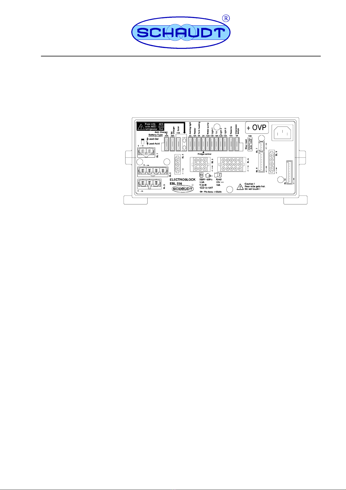
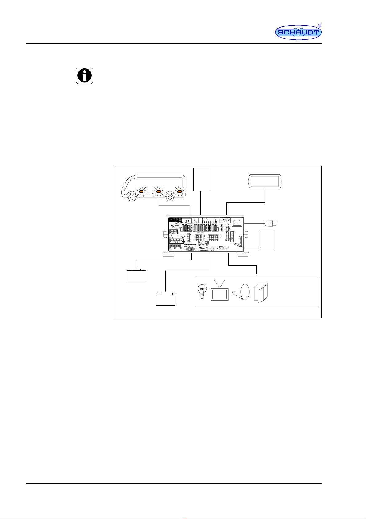
4 Application and Functions in Detail
Y
This device is intended solely for installation in a vehicle.
The EBL 226 C +OVP Electroblock is the central energy supply device for all
12 V consumers in the electrical system on board the motorhome/caravan. It
is normally located inside a cupboard or storage area and is accessible from
the front for fuse changes.
The electronic block is suitable for applications in which the risk of overvol-
tage is especially high. For example, lightning strikes in the public mains net-
work, generator operation, poor electronic installations or trips to foreign
countries.
For this, overvoltage protection is fitted in the electronic block between the
mains connection and the charge module.
R
EBL 226 C +OVP
DT/LT ...
+--
+--
Control and
display panel
Electrobloc
230 V AC
12V consumers
Living area battery
Starter battery Lighting
Pump
Heater
etc.
LR ...
Solar regulator
(accessory)
LAS ...
Additional charger
(accessory)
Side marking lights
Fig. 2 On-board power supply system
The EBL 226 C +OVP Electroblock contains:
F
Overvoltage protection OVP
F
a charge module for charging all connected batteries
F
the complete 12 V distribution
F
the fuses for the 12 V circuits
F
A battery monitor module
F
Other control and monitoring functions
A DT or LT ... control and switch panel must be connected for operation.
These devices control the electrical functions in the vehicle’s living area, inc-
luding accessories.
There are connections for an additional battery charger and a solar charge
regulator.
Overvoltage protection
OVP
Modules
System devices

Instruction Manual Electrobloc EBL 226 C +OVP
9
Date: 30.09.2009
811.573 BA / EN
Flat vehicle fuses protect the various circuits. Exceptions here are the step
and the frost protection valve.
F
Excess temperature
F
Overload
F
Short circuit
230 V AC ±10 %, 47 to 63 Hz sinusoidal, protection class I
12 V outputs may be loaded with max. 90% of the rated current of the re-
spective fuse (see also assembly instructions or front panel).
4.1 Battery functions
6-cell lead acid or lead gel batteries, 55 Ah and above
Simultaneous charging of the starter battery and the living area battery via
the alternator, parallel connection of the batteries via a cut-off relay
the battery cut-off (enabled on the DT/LT ... control and switch panel) isola-
tes the following connections from the living area battery:
F
all 12 V consumers
F
the frost protection valve
This prevents slow discharge of the living area battery by the standby cur-
rent during shutdown of the vehicle (discharge with approx. 4 Ah in month).
The batteries can still be charged using the Electrobloc, the alternator, an
auxiliary charging unit or the solar charge regulator, even when the battery
cut-off switch is switched off.
The switching option provided by the battery selector switch ensures opti-
mum charging of the two battery types, lead gel and lead acid.
The battery monitor of the DT/LT ... control and switch panel constantly mo-
nitors the living area battery with dynamic voltage threshold. Lower di-
scharge currents cut off ”earlier” than with larger currents. This provides im-
proved total discharge protection. Monitoring is also performed in the
switched-off state. A warning message is displayed below 12.0 V (,depen-
ding on current drain).
If the voltage of the living area battery sinks further, falling below 10.5 V, the
battery monitor immediately switches off all 12 V consumers. The control
and switch panel also switches itself off. Only the frost protection valve con-
tinues to be powered (so it stays closed). Before switch-off, all switch states
are the value of the battery capacity are stored and restored after power-on.
Protective circuits
Mains connection
Current-carrying
capacity
Suitable batteries
Battery charging
during mobile operation
Battery isolation
Battery selector switch
Battery monitor with
automatic disconnect

Instruction Manual Electrobloc EBL 226 C +OVP
10
Date: 30.09.2009 811.573 BA / EN
If an overload or an insufficiently charged living area battery causes the vol-
tage to fall so low that the automatic disconnector is triggered, any non-es-
sential consumers should be switched off.
If need be, the 12 V supply can begin operation for a short time. To do this,
switch on the 12 V main switch on the DT/LT ... control and switch panel.
However, if the battery voltage remains below 11.0 V, the 12 V power supply
can not be turned back on.
Fully charge the living area battery as soon as possible. For further informa-
tion, see ”Battery voltages” in the instruction manual of the relevant DT/LT ...
control and switch panel .
4.2 Additional functions
This relay supplies the AES/compressor refrigerator with power from the
starter battery when the vehicle engine is running and the D+ connection is
live. An AES/compressor refrigerator is powered by the living area battery
when the vehicle engine is not running.
The step output is protected by a self-resetting 15A fuse.
If a fault occurs, such as overcurrent, the self-resetting fuse interrupts the
relevant circuit.
After rectification of the fault, the fuse automatically resets after approx. 1
minute.
Maximum permitted charge current 14 A, protected with 15 A
Depending on the solar charge regulator used, either only the living area
battery is charged or the living area battery and the starter battery.
The power supply to the awning light is automatically interrupted as soon as
the engine is started and the D+ connection is live. The awning light can still
be used even if the 12 V power supply is switched off.
The tank heater is enabled via the DT/LT ... control and switch panel. The
tank heater can still be used even if the 12 V power supply is switched off.
The side marking lights are switch on via the integrated relay. They are po-
wered from the start battery. The relay is activated via terminal 58.
5Maintenance
The Electrobloc requires no maintenance.
Clean the electronic block with a soft, slightly damp cloth and mild detergent.
Never use spirit, thinners or similar substances. Do not allow liquids to enter
the electronic block.
No part of this manual may be reproduced, translated or copied without ex-
press written permission.
Automatic switch
function for
AES/compressor
refrigerator
Step fuse
Battery charging with
solar charging regulator
Awning light
Tank heater
Side marking lights
Cleaning
E

Instruction Manual Electrobloc EBL 226 C +OVP
11
Date: 30.09.2009
811.573 BA / EN
Appendix
A EC Declaration of Conformity
Schaudt GmbH hereby confirms that the design of electronic block EBL 226
C +OVP complies with the following relevant regulations:
EC-Low Voltage Directive
73/23/EEC as amended on 22.07.93
Directive on electromagnetic compatibility
89/336/EEC with amendment 92/31/EEC
The original EC Declaration of Conformity is available for reference at any
time.
Schaudt GmbH, Elektrotechnik & Apparatebau
Planckstraße 8
88677 Markdorf
Germany
B Special fittings/accessories
Schaudt DT .../LT ... switch panel (required for operation)
Schaudt battery charger LAS ... with max. 14 A charge currency, including
suitable connection cable (MNL).
Schaudt Solar-charge regulator type LR ... for solar modules with an overall
currency of 14 A with 3-pole connection plug and connection cable
C Customer service
Schaudt GmbH, Elektrotechnik & Apparatebau
Planckstraße 8
D-88677 Markdorf
tel.: +49 7544 9577-16 e--mail: kundendienst@schaudt-gmbh.de
Office hours Mon to Thurs 08.00 -- 12.00, 13.00 -- 16.00
Fri 08.00 -- 12.00
Returning a defective device:
³Fill in and enclose the fault report, see Appendix D.
³Send it to the addressee (free of charge).
Manufacturer
Address
Switch panel
Additional charger
Solar charge regulator
Customer service
address
Send in the device

Instruction Manual Electrobloc EBL 226 C +OVP
12
Date: 30.09.2009 811.573 BA / EN
D Fault report
In the event of damage, please return the defective device together with the
completed fault report to the manufacturer.
Device type: _______________________
Article no.: _______________________
Vehicle: Manufacturer: _______________________
Model: _______________________
Own installation? Yes -No -
Upgrade? Yes -No -
Following fault has occurred (please tick):
-Electrical consumers do not work -- which?
(please specify below)
-Switching on and off not possible
-Persistent fault
-Intermittent fault/loose contact
Other remarks:
E Technical data
230 V AC ±10%, 47 to 63 Hz sinusoidal, protection class I
1.9 A
Depending on the control and switch panel: approx. 5 -- 20 mA, plus con-
sumption of controller electronics of refrigerator
Measurement approx. 10 minutes after disconnection from the mains:
F
not connected to mains
F
12.6 V battery voltage
F
Battery isolation not enabled
F
Control and switch panel lighting off
F
12V main switch off
Loading of the D+ output of the alternator by the Electroblock approx. 1 mA
without current consumption on D+ point
12V outputs A maximum of 90% of the
nominal current of the relevant fuse
may be drawn.
Mains connection
Current consumption
Standby current from
Living area battery
D+ loading
Current-carrying
capacity

Instruction Manual Electrobloc EBL 226 C +OVP
13
Date: 30.09.2009
811.573 BA / EN
Frost ventilation valve output max. 0.1 A
D+ point max 1 A
Characteristic charging curve IUoU
Final charging voltage 14.3 V
Charge current 18 A in the entire mains voltage range,
electronically limited, minus the
charge current into the vehicle battery
Voltage for float charge 13.8 V with automatic switchover
New charge cycle, with battery voltage below 13.8 V
Switchover to main charging with a few seconds delay
Main charge
I
Full charge
Uo
Float charge
U
4hwithleadacid
16 h with lead gel
Time
14,3
13,8
Solar
charging
V
Fig. 3 Example of the charge voltage curve with Electroblock EBL 226 C +OVP
I Main charge with maximum 18 A charging current, electronically limi-
ted, up to final charging voltage. Start of charge also for totally dischar-
ged batteries.
Uo Automatic changeover to full charge with constant 14.3 V. The duration
of the fully charge phase depends on the type of battery and can be
adjusted at the device:
U Automatic changeover to trickle charge with constant 13.8V. In the
trickle charge phase, the voltage at the output of the charging module
is constant.
Start of a new charging cycle by switching over to main charge, if the battery
voltage falls below 13.8 V for more than 5 seconds when loaded. Start of
charge also for totally discharged batteries. The internal charge module can
also be operated without living area battery.
For mains operation, the starter battery is also charged (with maximum
charge current of 6 A).
Maximum permitted charge current 14 A, protected with 15 A
Simultaneous loading of living area battery by alternator
Batteries connected in parallel via a cut-off relay
Cut-off voltage approx. 10.5 V
Minimum battery voltage for approx. 11.0 V
switch-on via the
12Vmainswitchonthe
control and switch panel:
Battery charging, living
area battery with mains
connection
Battery charging, starter
battery with mains
connection
Battery charging via
solar charge regulator
Battery charging
during mobile operation
Battery monitor
Instruction Manual Electrobloc EBL 226 C +OVP
14
Date: 30.09.2009 811.573 BA / EN
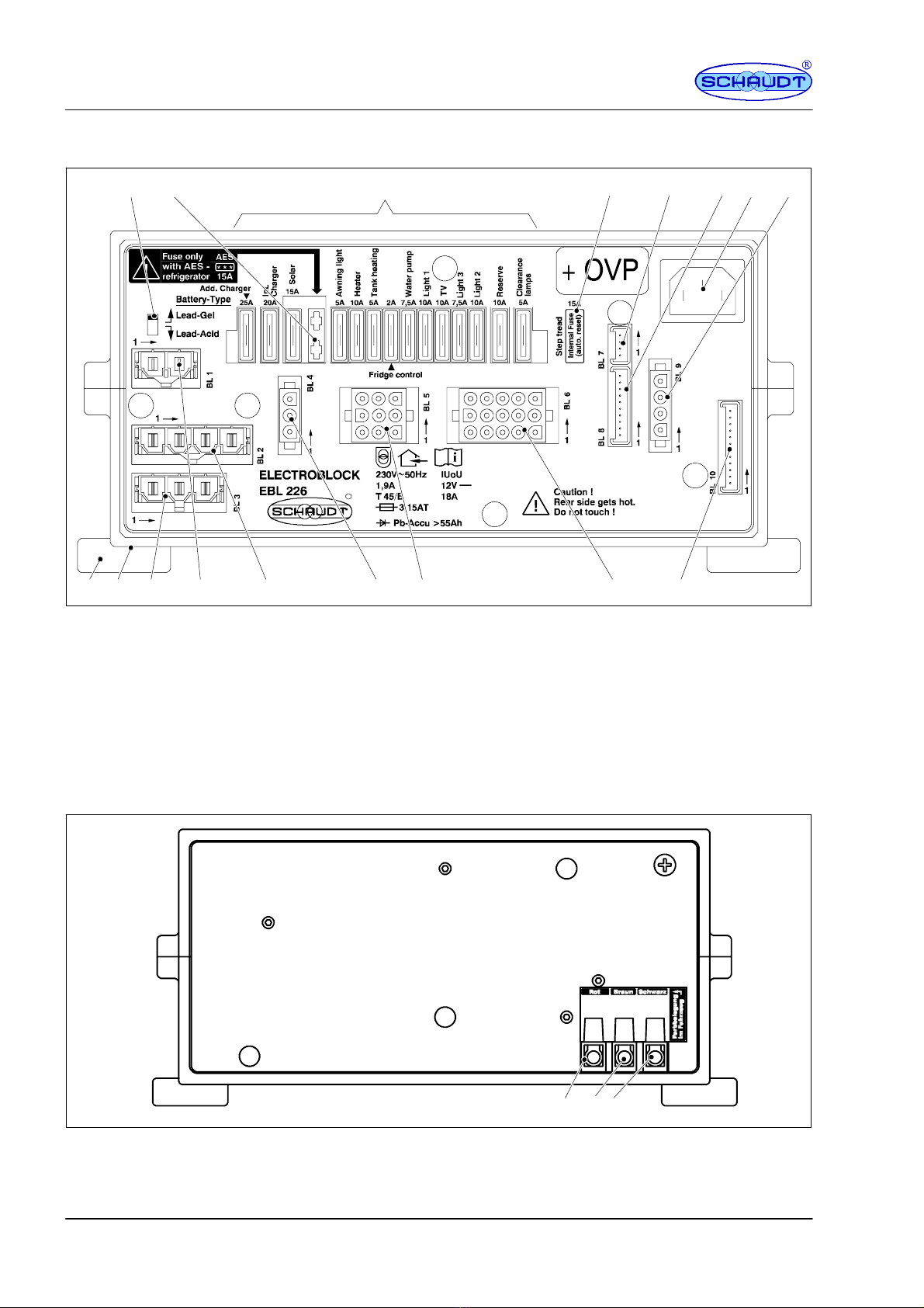
F Design
R
11
23 45
67 8
12 913
1
14 10151617
Fig. 4 Design, Electroblock EBL 226 C +OVP (front)
1 Selector switch acid/gel battery
2 AES refrigerator fuse
3 Flat vehicle fuses
4 Self resetting step fuse (internal)
5 Connection block solar regulator (measurement
signal)
6 Connector, DT .../LT ... control and switch panel
7 Mains connector
8 Connector block, refrigerator supply D+,
Battery sensor/control lines
9 Connector, DT .../LT ... control and switch panel
10 Connector block, light, refrigerator control, D+,
TV, Side marking lights, tank heater
11 Connection block, awning light, pump, heater,
light
12 Connection block, solar regulator (supply)
13 Connection block, refrigerator, step
14 Connection block, additional charger
15 Connection block, refrigerator supply
16 Housing
17 Assembly flaps
Starter
Battery
+
NegativeBattery
-- +
Living area
123
Fig. 5 Design, electronic block EBL 226 C +OVP (rear)
1 Connection, living area battery
2 Connection, earth
3 Connection, starter battery

Instruction Manual Electrobloc EBL 226 C +OVP
15
Date: 30.09.2009
811.573 BA / EN
G Block diagram/connection diagram
DA21
1
Block 9
2
1
3
4
nc
4
2
3
1
6
7
9
5
8
5
12
4
15
11
6
7
14
8
9
3
13
2
1
10
3
13
2
10
1
Block 6
5A
D
10A
Side marking lamps
Input
--- --- S p a r e
+Spare
--- --- S i d e m a r k i n g l a m p s
+Sidemarkinglamps
M N L --- S o c k e t 1 5 x P a r t 2
CFrost protection valve heater system
M N L --- --- S o c k e t 4 x
Block 6
D+ base
+ Refrigerator control
+Tankheater
2
+TV
+Light2
+Light3
--- --- L i g h t 2
--- --- T V
--- --- L i g h t 3 3
--- --- T a n k h e a t e r
+Heater
Block 2
Block 3
at block 8 control panel
Block 7
Block 6
Block 1
at block 10 control panel
Block 5
--- --- L i g h t 1
--- --- H e a t e r
--- --- A w n i n g l i g h t
15A
PolySwitch
+ Refrigerator
Molex Minifit SR 4 x
Negative refrigerator
+Step
Negative step
refrigerator
+SB
20A
Negative SB refrigerator
Molex Minifit SR 3 x
M N L --- --- S o c k e t 9 x
Shunt
MS relay 1
15A
Important!
refrigerator!
LAB = living area battery
SB = starter battery
ThefuseisonlyusedfortheAES
60A
A8 A24
A
Switching stage
7,5A
10A
10A
10A
10A/max. 20A
Awning light
Refrigerator
5A
+ Awning light
+Light1
Negative pump (switched)
+Pump
Lumberg MSFQ/0 12x
HS 100
E
A
A
Negative sensor LAB
Mains indicator
MS relay 2 Off
MS relay 1 Off
MS relay 1 On
MS relay 2 On
Shunt consumer
+SB
+LABsensor
Shunt battery
2A
2A
60A
Negative LAB sensor
D+* base
D+ input
+LABsensor
Module
8
Charging relay B1
20A
R
AES
***
Int. Charger
1
230V AC
socket
Mains 230V~ 50Hz
14,3V--- --- 18A
LAS 1218--- --- 5
A9
A30
A7
A2
A1
A16
A6 A17
A5
Switch between
lead gel/lead
acid battery
Circuit board KPL EBL 226
A7
A9
S 1218--- --- 2
Battery cut-
off relay
E 2 0 --- --- 3 F --- --- s c r e w t e r m i n a l
Thenegativepoleofthelivingarea
battery must be connected externally
to the negative pole of the starter battery.
A3
A2
A1
+LAB
+SB
Negative LAB *
60A
60A
7,5A
Lumberg MSFQ/0 10 x
Signal Solar WB
Signal Solar SB
Pump
1
4
6
7
4
3
2
Signal SB
MNL socket cap 3 x
Lumberg MSFQ/0 4 x
Negat.
+SB
+LAB 3
2
1
15A
3
2
1
+ Lighting
Negative lighting
Schaudt solar charger
regulator type LRS...
with connection cable
Solar module
Frost protection valve
25A
Molex Minifit SR 2 x
Negative auxiliary charging
A
E
60A
MS relay 2
Tank heater
D+ Booster
5A
B
2A
C
B
2
D+ B
Tank heater 3
R
5
10
9
8
nc
+ Auxiliary charging unit
Switching stage
OVP
11
7
6
10
5
2
1
4
3
12
9
8
11
7
6
10
5
2
1
4
3
12
9
2
1
3
4
2
1
3
2
1
3
4
2
3
1
6
7
9
5
8
5
12
4
15
11
6
7
8
9
14
nc
nc
nc
1
4
6
7
2
3
5
10
9
8
1
4
3
2
1
4
3
2
1
4
3
2
2
1
2
1
Signal LAB
* active ground
M N L --- S o c k e t 1 5 x P a r t 1

Instruction Manual Electrobloc EBL 226 C +OVP
16
Date: 30.09.2009 811.573 BA / EN
(blank page)
Table of contents
Other Schaudt Automobile Accessories manuals


Popular Automobile Accessories manuals by other brands


Fabtech
Fabtech FTS51009 installation instructions

ULTIMATE SPEED
ULTIMATE SPEED UASB 12 A1 operating instructions

Menabo
Menabo ICEBERG Fitting instructions

Federal Signal Corporation
Federal Signal Corporation ARJENT S2 SERIES Installation and maintenance instructions

Edscha Trailer Systems
Edscha Trailer Systems DrySystem quick guide

Tellur
Tellur TLL151261 user manual