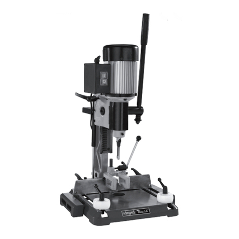
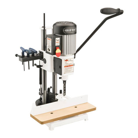
Scheppach Chisa 7.0 Assembly instructions

Chisa 7.0
Art.-Nr. 1902502901
0-2012
1902502850
DStemmmaschine
Original-Anleitung
GB Mortiser
Translation from the original instruction
manual
FR Mortaiseuse
Traduction du manuel d’origine

03 – 08
09 – 13
14 – 18
U2
D
GB
FR

HCM 25 Mortiser

Garantie
Offensichtliche Mängel sind innerhalb von 8 Tagen nach Erhalt der Ware
anzuzeigen, andernfalls verliert der Käufer sämtliche Ansprüche wegen solcher
Mängel. Wir leisten Garantie für unsere Maschinen bei richtiger Behandlung
auf die Dauer der gesetzlichen Gewährleistungsfrist ab Übergabe in der Weise,
dass wir jedes Maschinenteil, dass innerhalb dieser Zeit nachweisbar in Folge
Material- oder Fertigungsfehler unbrauchbar werden sollte, kostenlos ersetzen.
Für Teile, die wir nicht selbst herstellen, leisten wir nur insoweit Gewähr, als
uns Gewährleistungsansprüche gegen die Vorlieferanten zustehen. Die Kosten
für das Einsetzen der neuen Teile trägt der Käufer. Wandlungs- und Minde-
rungsansprüche und sonstige Schadensersatzansprüche sind ausgeschlossen.
Warranty
Apparent defects must be notified within 8 days from the receipt of the goods.
Otherwise, the buyer’s rights of claim due to such defects are invalidated. We
guarantee for our machines in case of proper treatment for the time of the sta-
tutory warranty period from delivery in such a way that we replace any machine
part free of charge which provably becomes unusable due to faulty material
or defects of fabrication within such period of time. With respect to parts not
manufactured by us we only warrant insofar as we are entitled to warranty
claims against the upstream suppliers. The costs for the installation of the new
parts shall be borne by the buyer. The cancellation of sale or the reduction of
purchase price as well as any other claims for damages shall be excluded.
Garantie
Des défauts visibles doivent être signalés au plus tard 8 jours après la récep-
tion de la marchandise, sans quoi l’acheteur perd tout droit à des redevances
pour de tels défauts. Nous garantissons nos machines, dans la mesure où
elles sont maniées correctement, pour la durée légale de garantie à compter
de la remise dans ce sens que nous remplaçons gratuitement toute pièce de
la machine devenue inutilisable durant cette période pour des raisons d’erreur
de matériau ou de fabrication. Toutes pièces que nous ne fabriquons pas nous-
mêmes ne sont garanties que si nous possédons des droits à la garantie vis-à-
vis des fournisseurs respectifs. Les frais pour la mise en place des nouvelles
pièces sont à la charge de l’acheteur. Tous droits à rédhibition et toutes pré-
tentions à diminutions ainsi que tous autres droits à l’indemnité sont exclus.
Händler:
Dealer:
Vendeur:
Gerätetype:
Appliance type:
Type d’appareil:
Gerätenummer:
Serial number:
Numéro de l’appareil:

deutsch 3
Hersteller:
scheppach
Fabrikation von Holzbearbeitungsmaschinen GmbH
Günzburger Straße 69
D-89335 Ichenhausen
Verehrter Kunde,
Wir wünschen Ihnen viel Freude und Erfolg beim Arbeiten
mit Ihrer neuen Maschine.
Hinweis:
Der Hersteller dieses Gerätes haftet nach dem geltenden
Produkthaftungsgesetz nicht für Schäden, die an diesem
Gerät oder durch dieses Gerät entstehen bei:
teilen,
Wir empfehlen Ihnen:
Lesen Sie vor der Montage und vor Inbetriebnahme den
Maschine kennenzulernen und ihre bestimmungsgemäßen
Einsatzmöglichkeiten zu nutzen.
Sie mit der Maschine sicher, fachgerecht und wirtschaftlich
-
ten sparen, Ausfallzeiten verringern und die Zuverlässig-
keit und Lebensdauer der Maschine erhöhen.
-
ten.
vor Schmutz und Feuchtigkeit, bei der Maschine aufbewah-
der Arbeit gelesen und sorgfältig beachtet werden. An der
Maschine dürfen nur Personen arbeiten, die im Gebrauch
der Maschine unterwiesen und über die damit verbunde-
nen Gefahren unterrichtet sind. Das geforderte Mindestal-
ter ist einzuhalten.
Allgemeine Hinweise
-
tionen werden nicht anerkannt.
nungsanweisung mit dem Gerät vertraut.
satzteilen nur Original-Teile. Ersatzteile erhalten Sie bei
Ihrem -Fachhändler.
Chisa 7.0
Lieferumfang
Karton Untergestell
(Sonderzubehör)
Untergestell
Kleinteilebeutel
Karton Stemmmaschine
Stemmmaschine mit Motor
2 Handradgriffe
Futterschlüssel
Stemmeisen
Holztisch
Technische Daten
Abmessung B/T/H mm Tischgröße B/T mm Tischhöhe mm Tischverstellung B/T mm Bohrhub mm 220
Abstand Bohrer –
Anschlag mm Bohrtiefe max. mm Bohrergröße max. mm 25
Werkstückhöhe max. mm 200
Tischbewegung mm Spindelgeschwindigkeit
1/min Stemmeisen-Leistung mm Stemmeisen-Schaft/
Buchsengröße mm 19,05
Stemmeisen-Hub max. mm 220
Abstand
Anschlag – Stemmeisen-
Mitte mm Futterkapazität mm 16
Gewicht kg 91
Motor
Elektromotor Aufnahmeleistung P1 W Drehzahl Stecker Schuko
Technische Änderungen vorbehalten!
m
In dieser Bedienungsanweisung haben wir Stel-
len, die Ihre Sicherheit betreffen, mit nebenste-
hendem Zeichen versehen.
mAllgemeine Sicherheitshinweise
-
ter, die an der Maschine arbeiten.
bestimmungsgemäße, sicherheits- und gefahrenbewusst
Insbesondere Störungen, die die Sicherheit beeinträch-
tigen können, umgehend beseitigen (lassen)!
-
-
ne beachten.
-
ne vollzählig in lesbarem Zustand halten.
und Hände durch das rotierende Schneidewerk.
festem Grund steht.
Leitungen verwenden.
Maschine fern.

sein, dürfen aber nur unter Aufsicht an der Maschine
arbeiten.
werden.
-
fällen freihalten.
Armbanduhren ablegen.
Anschluss.
nicht demontiert oder unbrauchbar gemacht werden.
ziehen und Stillstand des rotierenden Werkzeuges ab-
warten.
Schutzeinrichtungen und Abdeckungen montiert sein.
demontiert oder unbrauchbar gemacht werden.
-
klemmter Holzstücke die Maschine stillsetzen. Netzste-
cker ziehen!
-
beiten nur bei abgeschaltetem Motor durchführen. Netz-
stecker ziehen!
-
ten. Netzstecker ziehen!
-
triebnahme die Maschine wieder ordnungsgemäß an das
Stromnetz anschließen.
der Elektroinstallation dürfen nur von Fachkräften aus-
geführt werden.
-
-
beiten sofort wieder montiert werden.
mBestimmungsgemäße Verwendung
Die Maschine entspricht der gültigen EG-Maschinenrichtli-
nie.
erfolgen. Die Maschine vorne und hinten unter dem Ge-
stell anfassen und anheben.
-
schine auf einem stabilen, tischähnlichen Gestell stand-
fest aufgesetzt werden. Die Arbeitshöhe soll mindestens
850 mm betragen.
frei von störenden Fremdkörpern sein, um Unfälle vorzu-
beugen.
-
sein.
von Holz und holzähnlichen Werkstoffen konstruiert. Es
dürfen nur Original-Werkzeuge und Zubehör eingesetzt
sowie bestimmungsgemäß, sicherheits- und gefahren- benutzen. Insbesondere Störungen, die die Sicherheit
beeinträchtigen können, umgehend beseitigen (lassen).
Herstellers sowie die in den Technischen Daten angege-
benen Abmessungen müssen eingehalten werden.
sonstigen allgemein anerkannten sicherheitstechni-
oder repariert werden, die damit vertraut und über die
-
gen an der Maschine schließen eine Haftung des Her-
steller für daraus resultierende Schäden aus.
-
werkzeugen des Herstellers genutzt werden.
bestimmungsgemäß. Für daraus resultierende Schäden
mRestrisiken
Die Maschine ist nach dem Stand der Technik und den aner-
kannten sicherheitstechnischen Regeln gebaut. Dennoch kön-
nen beim Arbeiten einzelne Restrisiken auftreten.
rotierende Werkzeug bei unsachgemäßer Führung des
Werkstückes.
bei unsachgemäßer Haltung oder Führung, wie Arbeiten
ohne Anschlag.
-
nungsgemäßer Elektro-Anschlussleitungen.
-
sorgfältig gelesen werden.
-
-
-
-
achtet werden.
deutsch 5
Montage
Sämtliche Montage- und Umrüstarbeiten dürfen nur bei gezo-
genem Netzstecker erfolgen.
Die Stemmmaschine muss auf dem Untergestell mit vier
Sechskantschrauben M12 x 120 (mitgeliefert) befestigt
Stellen Sie sicher, dass auf beiden Seiten der Maschine
ausreichend Platz verbleibt für die Werkstückgröße, die
Sie bearbeiten möchten.
Inbetriebnahme
Beachten Sie die Sicherheitshinweise!
WICHTIG: Die Inbetriebnahme der Maschine darf nur mit
komplett montierten Schutz-und Sicherheitseinrichtungen
erfolgen.
Einbau von Stemmeisen und Bohrer
dem Loch nach vorne. Ziehen Sie die Schraube nur so
Schlitz in der Seite des Stemmeisens nach links oder
rechts, nicht nach vorn oder hinten. Das ermöglicht den
Auswurf der Späne bei der Herstellung von Langlöchern
Stemmeisenpunkten zwischen 0,8 mm und 1,6 mm ein-
gestellt werden, je nach Holzart.
Werkstückanschlag, Fig. 3
Der Werkstückanschlag wird am Tisch montiert.
geklemmt.
Fig. 1
Gestelltüre
Schalter
Tiefenanschlag
Tischanschlag
Schraubstock
Tisch
Untergestell Gasfeder
Stemmeisen
Werkstück-
anschlag
Handrad
Fig. 2
Sperrschraube
Stemmeisen
0,8 bis 1,6 mm ent-
sprechend Holzart
Fig. 3
Tisch
Schraubstock
Werkstückanschlag
Werkstückanschlag

6 deutsch
Arbeitshinweise
-
Sie es mit dem Schraubstock fest. Mit dem rechten
Handrad bewegen Sie den Tisch nach vorne und zurück,
mit dem linken Handrad wird der tisch nach links und
rechts bewegt.
der Länge des gewünschten Langlochs, dann ziehen Sie
die Flügelschrauben an.
Die verschiedenen Geschwindigkeiten für unterschiedli-
che Holzarten müssen durch Erfahrung erlernt werden. -
ken Handrad für jeden weiteren Schnitt weiterbewegt.
Späne ungehindert entfernt werden können. Schieben
Sie das Werkstück so, dass der Schlitz im Stemmei-
sen die Späne in den bereits ausgeschnittenen Teil des
Werkstücks schiebt. Siehe Fig. 6.
Achtung: Schnitt in mehreren Phasen von ungefähr je 2,5 cm Tiefe,
damit die Späne ausgestoßen werden können. Um beim
Herstellen von durchgehenden Langlöchern das Ausbre-
chen an der Werkstückunterseite zu verhindern, legen Sie
ein Stück Abfallholz unter das Werkstück als Abstützung.
mElektrischer Anschluss
Der installierte Elektromotor ist betriebsfertig angeschlos-
-
chen.
Wichtige Hinweise
-
lich) läßt sich der Motor wieder einschalten.
Schadhafte Elektro-Anschlussleitungen
An elektrischen Anschlussleitungen entstehen oft Isolati-
onsschäden.
Ursachen sind:
oder Türspalten geführt werden.
Führung der Anschlussleitung.
-
steckdose.
Solche schadhaften Elektro-Anschlussleitungen dürfen
nicht verwendet werden und sind auf Grund der Isolations-
schäden lebensgefährlich.
Elektrische Anschlussleitungen regelmäßig auf Schäden
Anschlussleitung nicht am Stromnetz hängt.
Elektrische Anschlussleitungen müssen den einschlägigen
Anschlag oben
Tiefenanschlag
Abschlag unten
Spindelkasten
Fig. 5
Tischanschlag links Tischanschlag rechts
Tisch
Fig. 6
Stemmeisen-Schlitz links
Stemmeisen-Schlitz
rechts
Werkstück in diese
Werkstück in diese

Ein Aufdruck der Typenbezeichnungen auf der Anschluss-
Wechselstrommotor
Querschnitt von 1,5 mm2, über 25 m Länge mindestens
2,5 mm2aufweisen.
Anschlüsse und Reparaturen an der Elektrischen Ausrüstung
dürfen nur von einer Elektro-Fachkraft durchgeführt werden.
-
triebseinheit mit Schalter einsenden.
Beachten Sie die Sicherheitshinweise!
Wartung
-
Stauben Sie die Maschine nach jedem Einsatz ab und, so-
weit nötig, verwenden Sie ein wenig Öl oder Schmiermittel,
um die Gelenke, beweglichen Teile usw. zu schmieren.
Schärfen von Stemmeisen und Bohrerspitze
Um die beste Leistung zu erzielen, müssen Stemmeisen
-
-
abgenutzt sind sollten sie ausgetauscht werden.
-
rers ein. Schleifen Sie die Innenkante, die Seiten der
-
2.Schärfen Sie das Stemmeisen mit einem Langloch-
Sie stets die richtige Zapfengröße, je nach Größe Ihres
-
nügen zwei oder drei Umdrehungen um das Stemmeisen
zu schärfen, wie in Fig. 8 gezeigt.
die inneren Ecken des Stemmeisens zu schärfen. Siehe
Fig. 9. Entfernen Sie eventuellen Grat an der Außenseite
des Stemmeisens mit einem feinen Ölstein.
Innere Kante der Spur
feilen Seiten des Hohlkehlpunktes feilen
Schneidkante feilen
Fig. 8
Zimmermannsfutter Schneider
Pilot
Stemmeisen
Stemmeisen in
Schraubstock mit
halten
Fig. 9
Feile
Stemmeisen

8 deutsch

english 9
Manufacturer
scheppach
Fabrikation von Holzbearbeitungsmaschinen GmbH
Günzburger Straße 69
D-89335 Ichenhausen
Dear customer,
We wish you much pleasure and success with your new
scheppach machine.
Note
In accordance with valid product liability laws, the manu-
facturer of this device shall not be responsible for damage
to and from this device which results from:
-
nal schrts.
-
ance with the legal and applicable electrical directives
We recommend
that you read through the entire operating instructions be-
fore putting into operation.
These operating instructions are to assist you in getting to
know your machine and utilize its proper applications.
The operating instructions contain important notes on how
you work with the machine safely, expertly, and economi-
cally, and how you can avoid hazards, save repair costs,
reduce downtime and increase the reliability and service
life of the machine.
operating instructions, you must be careful to observe your
country’s applicable regulations.
The operating instructions must always be near the ma-
chine. Put them in a plastic folder to protect them from
dirt and humidity. They must be read by every operator
before beginning work and observed conscientiously. Only
persons who have been trained in the use of the machine
and have been informed of the various dangers may work
-
served.
operating instructions and your country’s applicable reg-
ulations, you should observe the generally recognized
technical rules concerning the operation of woodworking
machines.
General notes
-
age. Inform the supplier immediately of any faults.
the machine by carefully reading these instructions.
-
placement parts. You can find replacement parts at your
scheppach dealer.
and year of construction of the machine.
Chisa 7.0
Supply extent
Carton box base (optional
equipment) Accessory pack
Carton box mortiser
Mortising machine with motor
Operating handle
2 Hand wheel handles
Chuck key
Chisel
Wooden table
Technical data
Dimensions W/D/H mm Table size W/L mm Table height mm Table adjustment W/D mm Drill stroke mm 220
Distance drill – fence mm Drill depth max. mm Drill size max. mm 25
Workpiece height max.
mm 200
Table movement mm Spindle speed 1/min Chisel capacity mm 6.35 – 25,.
Chisel shank/Bushing
size mm 19.05
Maximum chisel stroke
mm 220
Distance fence – centre
chisel mm Chuck capacity mm 16
Weight kg 91
Drive
Motor Consumption power P1 W Spindle speed Plug Schuko
Subject to technical modifications!
mIn these operating instructions we have marked the
places that have to do with your safety with this sign.
m Safety notes
who work on the machine.
condition in accordance with its designated use and the
instructions set out in the operating manual, and only
by safety-conscious persons who are fully aware of the
risks involved in operating the machine. Any functional
disorders, especially those affecting the safety of the
machine, should therefore be rectified immediately.
the machine.
to the machine are always complete and perfectly leg-
ible.
hands from the rotating cutting tool.
ground.
lines.

10 english
-
nected to the power supply.
Trainees must be at least 16 years of age, but may only
operate the machine under adult supervision .
from their work.
-
tension if a second person is working at the circular saw-
bench removing cut workpieces. The second person may
not stand anywhere else but at the take-off table end.
and wood scrap.
and other jewelry.
– see Electrical Connection.
-
moved or rendered unusable.
-
chine may only be carried out when the motor is switched
off. Pull the power supply plug and wait for the rotating
tool to completely stop.
rectifying any malfunctions.
and covers must be mounted.
rectifying any malfunctions.
the power supply plug.
even if only minor changes of place are envisaged. Prop-
erly reconnect the machine to the supply mains before
recommissioning.
completing repair and maintenance procedures.
m Use only as authorized
The machine corresponds to the valid EC guideline.
front and at the rear using both hands and lift the ma-
chine.
placed firmly upon a stable stand resembling a table.
The working height should be 850 mm.
-
chine must be clear of interfering foreign matter to pre-
vent accidents occurring.
i.e. nails or screws.
machining of wood and materials similar to wood. Only
original scheppach tools and accessories may be used.
Please observe the „Special Tool Accessories“.
condition in accordance with its designated use and the
instructions set out in the operating manual, and only
by safety-conscious persons who are fully aware of the
risks involved in operating the machine. Any functional
disorders, especially those affecting the safety of the
machine, should therefore be rectified immediately.
generally recognized safety-technical rules must also be
adhered to.
and operated by persons familiar with it and instructed
in its operation and procedures. Arbitrary alterations to
the machine release the manufacturer from all responsi-
bility for any resulting damages.
-
nal accessories and original tools made by the manu-
facturer.
is not responsible for any damages resulting from unau-
thorized use; risk is the sole responsibility of the opera-
mRemaining hazards
The machine has been built using modern technology in ac-
cordance with recognized safety rules. Some remaining haz-
ards, however, may still exist.
hands if it is incorrectly fed.
is not properly secured or fed, such as working without
a limit stop.
to injuries caused by electricity.
accessories must be observed and carefully read when
scheppach special accessories are used.
-
maining hazards which are not yet evident may still be
present.
instructions in „Safety Precautions“, „Proper Use“ and
in the entire operating manual.
Fig. 1
Access door
Switch
Depth stop
Table stop
Table
Enclosed
Operating handle
Gas spring
Chisel and bit
Work stop
Handwheel

english 11
Assembly and Installation
All assembly and retrofitting work may only be performed
when the mains plug has been disconnected.
The mortiser should be secured to the stand with four M12
x 120 hexagon screws (provided), using the holes in the
base. Make sure there is enough room on each side of the
mortiser for the size stock you plan to use.
Putting into Operation
Please observe the safety instructions!
The machine may only be put into operation when all of
the protective and saftey devices have been mounted.
Installing chisel and bit
the head. Tighten the screw just enough to hold the chis-
el in place.
Attention: The slot in the side of the chisel must show
to the left or to the right, never to the front or to the
back. This will allow the ejection of chips when making
mortises.
the chuck and lock it with the chuck key.
the chisel points, dictated by the type of wood.
Work piece stop, Fig. 3
The work piece stop is mounted to the table.
After the correct setting, it is fastened by means of the
clamping handles.
Operating instructions
vice. With the right hand wheel, move the table forward
and backward, with the left hand wheel move the table
to the left and to the right.
-
ily into the work piece by pulling the operating handle
down. Attention: The speed of pulling the handle down
must be efficient but smooth, in order to avoid burning
at the bit. Yet if the chisel and bit are pulled down too
-
ent rates of feed for different woods must be learned
through experience.
the left hand wheel for each successive cut. The direc-
tion of movement must allow the chips to clear freely.
Move the work piece so that the slot in the chisel is
releasing the chips into the already cut part of the work
piece – see Fig. 6.
Fig. 2
Chuck
Lock screw
Chisel
0.8 to 1.6 mm accord-
ing to wood type
Fig. 3
Table
Work stop
Work stop
Headstock stop
Depth stop
Headstock stop
Headstock
Fig. 5
Table stop Table stop
Table
Fig. 6
Chisel slot on left
Chisel slot on right
Move workpiece this
direction
Move workpiece this
direction

12 english
Attention: overheating and a possible breakage of chisel and bit.
When cutting deep mortises, make the cut in several stag-
es of approx. 25 mm depth each, to allow chips to clear. To
prevent breakout at the back of the work piece when cut-
ting through mortises, use a piece of scrap material under
the work piece as support.
mElectrical Connection
The electric motor is connected in a ready-to-operate state.
regulations.
The mains connection at the customer’s work place and
the extension cable used must correspond to these regula-
tions.
Important information
The motor automatically switches off if it is overloaded.
The motor can be switched on again after a cooling-down
period (varies timewise).
Faulty electrical connecting leads
Insulation damage often occurs at electrical connecting
leads.
Causes include:
through windows or the cracks of doors.
the connecting leads.
connecting lead from the wall socket.
Faulty electrical connecting leads such as these may not
be used and are highly dangerous due to the insulation
damage.
Check electrical connecting leads regularly for damage.
Ensure that the connecting lead is not attached to the
mains supply when you are checking it.
Electrical connecting leads must correspond to the relevant
on the connecting lead by regulation.
Single-phase motor
section of 1.5 mm2. Extension leads whose length is over
25 m must have a cross-section of at least 2.5 mm2.
fuse.
Connections or repairs on the electrical equipment may only
be carried out by an electrician.
Please give the following information if you have any en-
If your are sending back the motor, always send the com-
plete drive unit with the switch.
m Maintenance
as cleaning and lubrication and routine adjustment and
sharpening of the chisel and bit.
Dust the machine down after each use and, as necessary,
use light applications of oil or grease to lubricate linkages,
moving parts, etc.
Sharpening chisel and bit
The chisel and bit should be kept sharp for best perform-
lead to overheating and breakage to chisel or bit. If chisel
and bit are badly worn and become difficult to sharpen,
they should be replaced.
the original shape of the bit. File the inside edge of the
spur, the sides of the brad point, and the cutting edge
Do not file the outside edge of the spur as this will affect
the diameter of the bit.
correct size pilot. (Pilot size will differ depending on the
size of your chisel.) Depending on the degree of wear,
two or three turns of the cutter should be enough to
sharpen the chisel, as shown in Fig. 8.
File inner edge of spur File sides of brad point
File cutting edge
Fig. 8
Cutter
Pilot
Chisel
Hold chisel in soft-
faced vise jaws

english 13
the outside of the chisel with a fine oilstone.
Fig. 9
File
Chisel

Manufacteur:
scheppach
Fabrikation von Holzbearbeitungsmaschinen GmbH
Günzburger Straße 69, D-89335 Ichenhausen
Cher client,
au cours de vos travaux à venir, avec votre nouvel appareil
scheppach.
AVERTISSEMENT: Le constructeur de cet appareil n’est pas
responsable, conformément à la réglementation en vigueur
concernant la responsabilité des produits, des dommages
occasionnés par ou survenant à cet appareil et ayant pour
cause:
agréé.
originelles de scheppach“.
-
-
Nous vous conseillons de lire le texte du guide d’utilisation,
avant d’effectuer le montage et la mise en oeuvre. Ce ma-
tact avec la machine, vous permettra d’en exploiter correc-
tement toutes les possibilités. Les indications importantes
-
et raccourcir les périodes d’indisponibilité, comment enfin
augmenter la fiabilité et la durée de vie de la machine.
Outre les directives de sécurité figurant dans ce manuel,
vous devrez observer les prescriptions réglant l’utilisation
de la machine dans votre pays. Le manuel doit se trouver
en permanence à proximité de la machine. Mettez-le dans
naissance avant le début de son travail et respectera scru-
pourront travailler sur la machine les personnes instruites
de son maniement et informées des dangers inhérents à
celui-ci. L’âge minimum autorisé doit être respecté.
Outre les directives de sécurité contenues dans ce manuel
-
conduite des machines à travailler le bois.
Conseils généraux
-
tériorée pendant le transport. En cas de réclamation,
informer aussitôt le livreur.
-
rieures.
par l’étude du guide d’utilisation.
Chisa 7.0
Volume de la livraison
Boîte carton bâti
(équipement optionnel) Sachet d’accessoires
Boîte carton mortaiseuse
Mortaiseuse avec moteur
Poignée de maniement
2 poignées volant
Clé mandrin
Ciseau
Table en bois
Dates techniques
Dimensions L/L/H mm Taille table mm Hauteur table mm Réglage table L/P mm Levée ciseau max. mm 220
Distance butée – centre
ciseau mm Profondeur forage max.
mm Taille foret max. mm 25
Hauteur bois max. mm 200
Mouvement table mm longitudinaltransversalRotations (moteur) tr/mn Capacité ciseau mm Tige ciseau/Taille douille
mm 19,05
Levée forage max. mm 220
Distance butée – centre
ciseau Capacité mandrin 16
Poids kg 91
Moteur
Moteur Aufnahmeleistung P1 W Vitesse broche tr/mn Stecker Schuko
m
Dans ce guide d’utilisation, nous avons repéré les
endroits relatifs à votre sécurité avec ce signe.
mConseils de sécurité
-
sonnes travaillant sur la machine.
emploi prévu en observant les instructions de service,
en tenant compte de la sécurité et en ayant conscience
du danger! Eliminer notamment (ou faire éliminer) im-
médiatement toute panne susceptible de compromettre
la sécurité!
sur la machine.
-
-
et aux mains avec la lame en rotation.
-
ble.

pas utiliser de cordon défectueux.
-
chée au réseau.
-
la machine.
-
peaux et de chutes de bois.
bagues, et montres.
-
chine ou les rendre inutilisables.
coupé. Débrancher la prise et attendre la mise au repos
de l’outil rotatif.
-
chine, débrancher la prise.
être montés pour le travail.
-
chine, débrancher la prise.
-
cordée à une installation d’aspiration au moyen d’une
conduite d’aspiration flexible et difficilement inflam-
-
ter le moteur et débrancher la prise.
séparer la machine ou l’installation de toute alimenta-
tion en énergie venant de l’extérieur! Avant la remise en
service, rebrancher la machine sur le réseau!
-
de l’électricité.
achevés, tous les dispositifs de protection et de sécurité
doivent être remontés immédiatement.
mUtilisation conforme
La machine correspond aux normes en vigueur dans la Com-
munauté Européenne.
plateau à deux mains et soulever l’ensemble.
doit être posée sur un support plane et stable. La hau-
teur de travail doit être au minimum de 850 mm.
-
ger ne doit se trouver autour du poste de travail et aux
alentours de la machine.
de corps étrangers, comme par exemple, des clous ou
des vis.
le bois ou des matériaux dérivés du bois. Il est impéra-
tif d’utiliser exclusivement des outils et des accessoires
-
ce mode d’emploi.
emploi prévu en observant les instructions de service,
en tenant compte de la sécurité et en ayant conscience
du danger! Eliminer notamment (ou faire éliminer) im-
médiatement toute panne susceptible de compromettre
la sécurité!
d’utilisation y joint doit être lu avec soin et suivi à la
lettre.
-
-
informées des dangers inhérents. Toute initiative de
modification de la machine exclut la responsabilité du
constructeur pour les dommages y faisant suite.
-
cessoires et des outils d’origine du constructeur.
conforme. Le constructeur n’assume pas de responsabi-
charge de l’utilisateur seul.
mRisques résiduels
Cette machine est à la pointe de la technique et répond aux
règles de sécurité actuellement en vigueur. Néanmoins, cer-
tains risques résiduels peuvent survenir pendant son fonction-
nement.
raison d’un mauvais serrage ou d’un mauvais guidage,
en cas de travail sans butée par exemple.
-
nir malgré toutes les précautions prises.
de sécurité“ et l’utilisation conforme aux prescriptions“

Montage
Il est impératif de tirer la prise secteur avant d’effectuer toute
opération de montage et de modifiaction.
hexagonaux M12 x 120 (fournis). Utiliser pour cela les
Mise en service
Montage de ciseau et foret
douille.
boulon. Attention: La rainure dans le côté du ciseau doit
se trouver à gauche ou à droite, jamais à l’avant ou à
des copeaux est facilité.
le mandrin et le serrer avec la clé de mandrin.
à 1,6 mm entre les deux points de ciseau selon le type
de bois.
Butée de la pièce à travailler, fig. 3
Une fois le réglage accompli, serrer la butée avec les poi-
gnées de serrage.
Conseils de travail
l’étau. Avec la main droite, pousser la table vers l’avant
à gauche et à droite.
Fig. 1
Porte du
bâti
Interrupteur
profondeur
Etau
Table
Poignée
de manie-
ment
à gaz
Ciseau et foret
Fig. 2
Mandrin
Foret
blocage
Ciseau
Projection foret 0,8 à 1,6
mm selon le type de bois
Douille
Fig. 3
Table
Etau travailler
à travailler
profondeur

longueur de la mortaise désirée, ensuite serrer les vis à
oreilles.
de maniement, insérer le ciseau et la pointe de foret dans
-
appuyer trop vite pour éviter la surcharge de la machine.
Les vitesses exigées par les différents types de bois doit
être apprises par expérience.
à pas à l’aide du volant gauche. La direction de mou-
peuvent être enlevés sans encombrement. Pousser la
transporte les copeaux à la partie de bois déjà coupée
– voir fig. 6.
Attention: Pour éviter un échauffement ou rupture de ci-
seau ou pointe de foret, il faut absolument observer cette
méthode.
En coupant des mortaises profondes, exécuter la coupe en
plusieurs phases de 2,5 cm de profondeur chacune, pour
travailler en faisant des trous au travers du bois, intercaler
mBranchements électriques
pour la mise en service immédiate. Le branchement cor-
câbles de rallonge utilisés, devront être conformes à ces
normes.
Indications importantes
En cas de surcharge du moteur, celui-ci s’arrête automati-
de temps variable), le moteur pourra être remis en mar-
che.
Câbles de rallonge électriques défectueux
-
Les causes en sont:
de fênetre ou de porte.
conduite non-appropriée des câbles de rallonge.
-
lant du câble de la prise murale.
Il est impératif de ne pas utiliser des câbles de rallonge élec-
triques présentant de tels défauts, ils représentent un danger
de mort de par leur endommagement de l’isolation.
-
mis hors cirucit.
du code de désignation sur le câble de rallonge est obli-
gatoire.
Moteur monophasé
une section transversale de 1,5 mm2, ceux de plus de
25 m de longueur, de 2,5 mm2au minimum.
action retardée.
Il est impératif que les branchements et réparations de l’équi-
pement électrique ne soient effectués que par un spécialiste
en la matière.
-
En cas de réexpédition du moteur à l’usine, il est nécessai-
Fig. 5
gauche Table
Fig. 6
Pousser le bois dans
cette direction
Pousser le bois dans
cette direction

Entretien
-
de foret.
-
-
vantes etc.
Affûtage de ciseau et pointe de foret
Pour obtenir un bon résultat, ciseau et pointe de foret
doivent être toujours bien affilés. Les arêtes coupantes
émoussées font des mortaises pas précises. En outre, elles
peuvent causer l’échauffement et la rupture du ciseau et
faut les remplacer.
intérieure, les côtés de la pointe de centrage et le dos
-
tourillon de guidage. Utiliser toujours la taille juste de
tourillon selon la taille de votre ciseau. Dépendant de
l’usure du ciseau, deux ou trois révolutions sont suffi-
coins intérieurs du ciseau – voir fig. 9. Enlever les ba-
d’huile.
Arête intérieure Pointe de centrage
Dos de foret
Fig. 8
Tourillon de guidage
Ciseau
Ciseau dans l’étau
Serrer avec des man-
chons souples
Other manuals for Chisa 7.0
1
Table of contents
Languages:
Other Scheppach Chain Mortiser manuals