Rated Grease Capacites for
GB-1000 Units Piped in Series
No. of Units Removal Efficiency
in Series 98.8% 99%*
2 13,094 lbs. 12,474 lbs.
3 19,641 lbs. 18,711 lbs.
4 26,188 lbs. 24,948 lbs
FIELD CUT RISER (24 SERIES)
INSTALLATION GUIDELINES
Tools needed: 7/16" Nut driver tool/bit (included), marker (included), tape
measure and drill with 1/2" chuck. Jigsaw, circular saw or reciprocating
saw will be needed if risers need to be cut.
NOTE: To remove a component or adjust its position, the Upper Band
Clamp needs to be loosened or removed using nut driver bit. The
Lower Band Clamp is factory set and should not be removed. For
proper fastening ensure clamps are tightened to 5 - 8 ft lbs. of torque
(same as a rubber no-hub coupling) prior to installation.
Riser Assembly Instructions/Steps
1. Set unit so the pipe connections line up with job site piping and
measure riser height needed from top of cover to finished grade.
See Table 1 to select risers needed.
2. Remove covers from adapters. Remove adapters from main unit. On
a level surface, pre-assemble the risers and adapters, adjusting the
components upwards or downwards to achieve the riser height
needed. Make sure to maintain minimum and maximum insertion
depths as shown in Figure 2. If components are too long, make a
circular line around the sidewall with marker and cut with a power
saw. The lowest cut line on the riser assembly will be 6" beyond the
riser height needed to allow for ideal insertion depth (See Figure 1).
An alignment mark should be drawn 2" beyond the riser height
needed which will align with the top of the base unit gasket. DO NOT
cut the alignment mark. The Adapters and risers should sit level with
each other. Tighten upper clamps to keep riser/adapter assembly
from shifting. Make alignment marks on the sidewalls at the top of all
riser gaskets to aid final assembly.
3. IMPORTANT: Before the next step, make sure both diffusers are
installed inside the main unit at the appropriate locations. Check if
there needs to be any flow control adjustment at the inlet diffuser
(see general installation instructions).
4. Take apart riser assembly and clean all sidewalls and insides of
gaskets to remove dust/debris. Install components into the main
units starting from the lowest riser and work your way up to finished
grade. Ensure that riser will not interfere with diffuser, allow min. 1"
clearance. Maintain minimum and maximum insertion depths for all
components (see Figure 2). Tighten Upper Clamps to specified
torque after correctly positioning components. Riser assembly may
need to be supported during backfill.
5. If tilting of the adapter is required to be flush with grade, do so
AFTER all clamps have been tightened with riser(s)/adapter in a
vertical and level position. Tilting is done using gasket flexibility.
Tilting before tightening clamps may ruin a perfect gasket seal.
Schier recommends tilting only the adapter versus the entire
riser assembly to make sure your riser height and proper tank
access is maintained.
6. If riser height conditions change after completing above steps,
there may be room for adjustment. As long as minimum and
maximum insertion depths are maintained (see Figure 2), the
adapters/risers can be adjusted/cut as many times as neces-
sary.When riser system installation is complete, see Leak/Seal
Testing procedure if required.
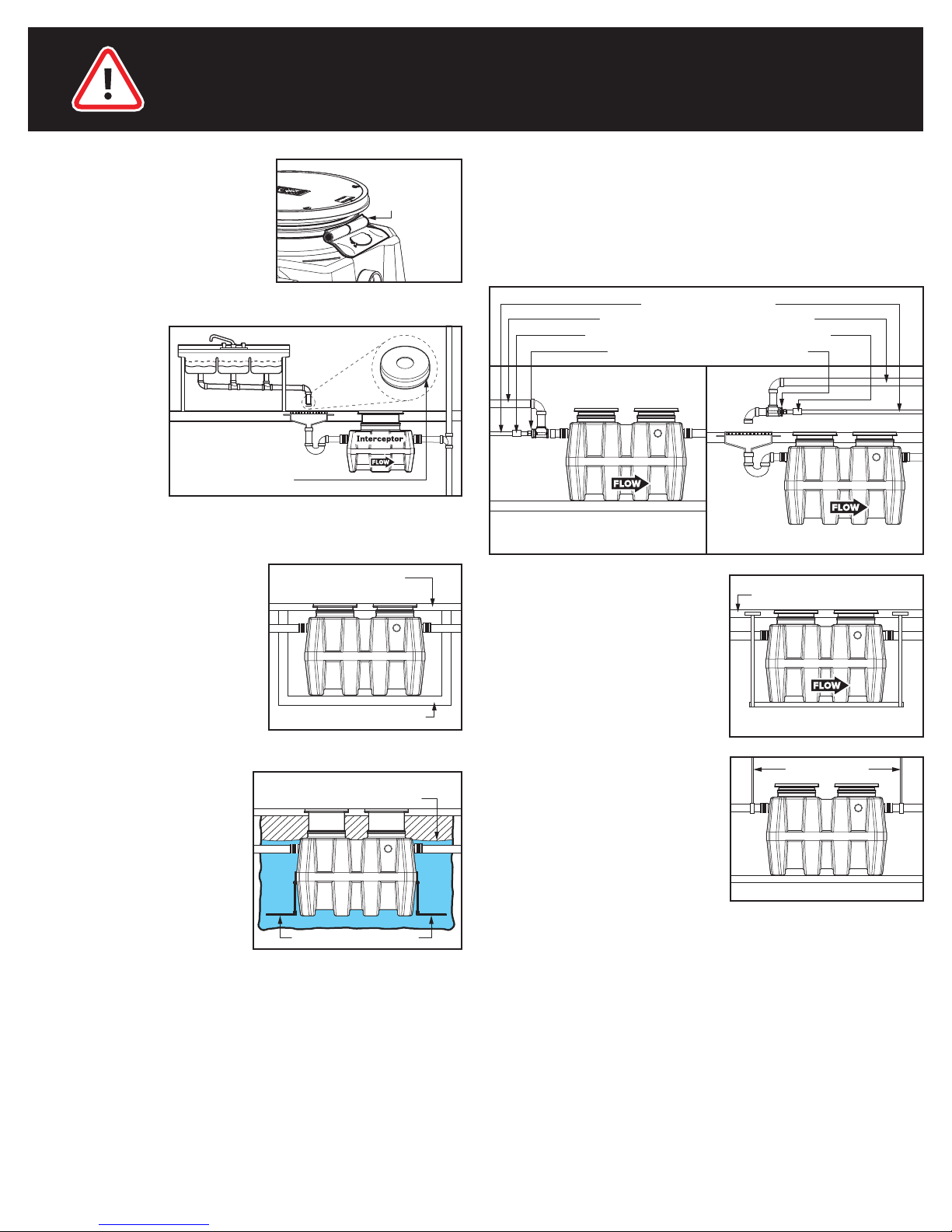
SERIES INSTALLATION OF
MULTIPLE GREASE INTERCEPTORS
For lower flow rates and higher grease storage requirements.
For below grade installations it is recommended to install a two-way
cleanout tee extended to finished grade before the inlet of the first
unit, after the outlet of the last unit and in between units (if there is a
long run of pipe between units) for line cleaning purposes.
NOTE: When the flow control plate is required, it should only be
installed on the first unit in the series.
Units piped in series are certified to ASME A112.14.3
(Type C) and CSA B481.1 and include an internal flow
control. External flow control with vent not required.
Top View of 4 GB-1000
Units Piped in Series
Table 1
Riser Height Needed Risers Required
0 - 3-1/2" None (use adapter)
5" - 23" SR24 (x2)
>23" - 38" LR24 (x2)
>38" - 43" SR24 (x4)
>43" - 58" SR24 (x2) + LR24 (x2)
>58" - 72" LR24 (x4)
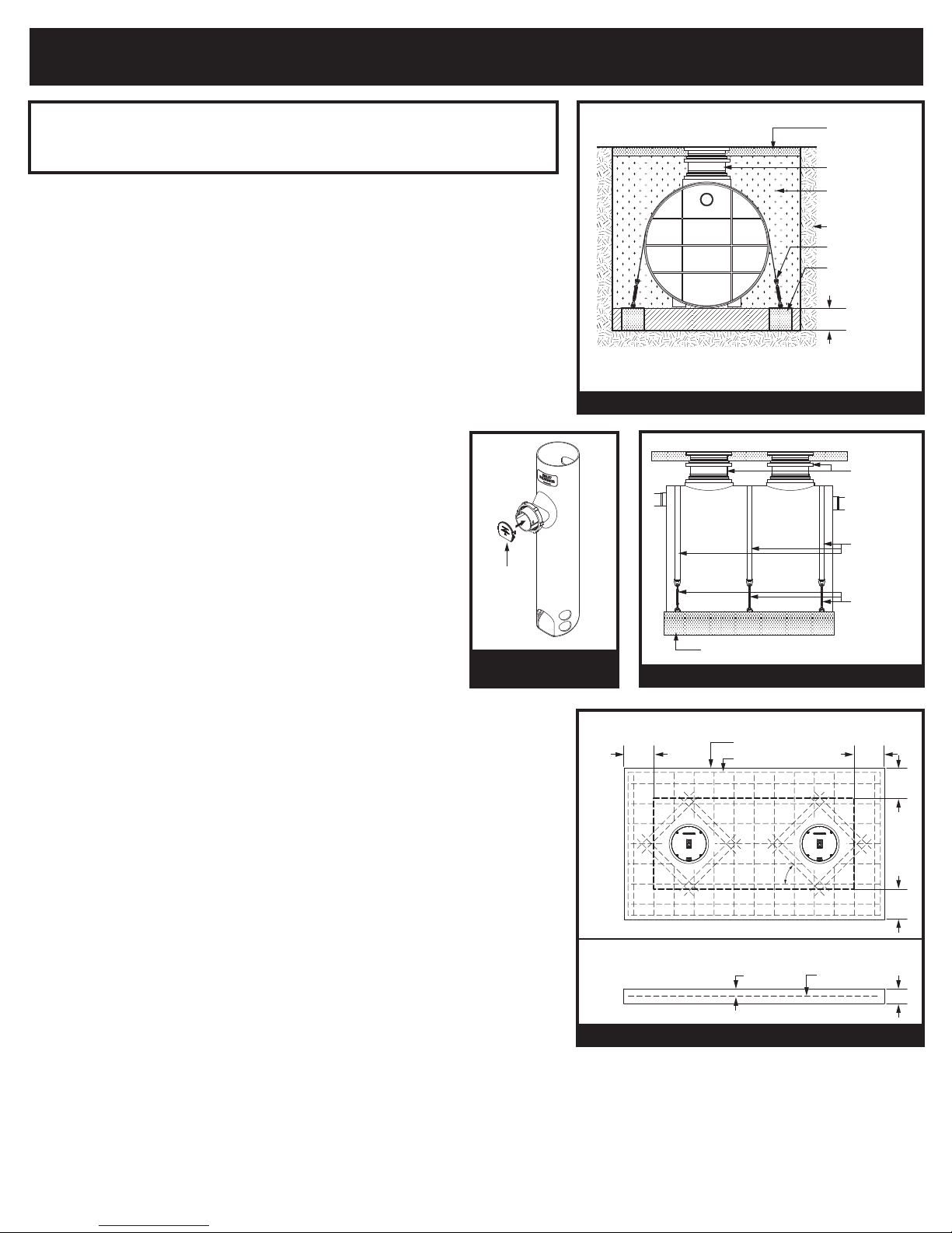
Riser
Height
Needed
Adapter
Riser
Cut Line
Alignment Mark
Figure 1 - Riser Measurements
Field Cut Riser
Components
6"
2"
4"
LR24
Long Riser
Adapter
SR24
Short Riser
Adapter (shown)
or Riser
Cover
Gasket
Upper Band Clamp
(
field adjustable)
Lower Band Clamp
(
factory set - do not
adjust or remove)
GB Unit (shown)
or Riser
Figure 2 - Insertion Depths
SERIES INSTALLATIONS
2-1/2" Minimum Insertion Depth
4" Maximum Insertion Depth
(into GB unit only)
page 4 of 4
057-0890-03
INSTALLATION (2 of 2)


 Operation and maintenance instructions")